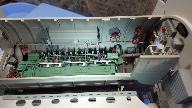
Well, this compartment is just about done. After several dry fitting attempts, I had what I think was the best way to add the last bulkhead to the compartment. I started with the two tabs at the top of the bulkhead and then worked my way down. I was able to use some pretty good size clamps so I went with normal Tamiya thin cement instead of CA. The floor has a good amount of flex possible so it was then easy to put it into the slot on the bulkhead. Lastly the bottom pieces lined up pretty well and some more clamps and after about 30 minutes she was very solid. With the heft of the plastic bulkheads and ribs at the bottom this compartment is very stable. The one long hanging pipe was then glued to the bulkhead. Here is a picture:
Here is a second picture using a flash to get a little brighter image. I am using my phone for the pictures, so I apologize for the quality as I am not a photographer.
The next step was to get those pipes on the roof piece to mate up with the ones on the engine. I double-checked the instructions and it turns out that there are only two that are supposed to match up. The third seem to just end. Perhaps it was capped and used for some kind of pressure relief? I was really surprised to see how close it was after all my messing around. The one pipe met up almost exactly and the other was only off a bit. I did need to trim a very small piece of length off as they were overlapping. One joint just needed a small drop of regular cement and the other got some CA as there was a bit of a bend to the joint. That was probably more my fault of not getting the proper alignment of the pieces when I glued them separately. The red circles show where the joints are.

This next picture shows how the exhaust piece a cut comes out of the roof part and lies in the cutout on the top of the bulkhead. It will extend onto the top of the roof of the next compartment and when those two are mated up I will add it in.
This picture shows the exhaust as it comes down from the roof and bends in and around and mates up behind the engine. I did not glue it at all as I need to be able to make sure it fits at the top, so just some tape for now. You cannot see behind the engine so if it off a bit you will never know. You can also see the join of that long pipe section.
This picture shows how the ribs from the bottom match up to the roof piece. These are not going to be visible at all. It is not a perfect flush fit as the stick out a little behind the curve of the pieces. I don’t know if they will have to be trimmed when I fit it into the hull or if there is some room. Time will tell on that one.
These are the last three long pieces that need to be attached. The instructions say to put these in first before the last bulkhead, but I chose to wait as I had some maintenance to do joining those pipes, replacing the valve wheel I knocked off, and I just wanted to make sure about the LED diodes too.
Here they are after being attached. No issues. The curve in the one pipe going around that one large valve wheel is real not an optical illusion. For all the issues we have read about with some Trumpeter kits, this one so far has been pretty good to work with from the assembly perspective. I have no idea about historical accuracy.
Now for what we all want to see and why I got this one; the lighting. Let me say these were taken in a very dark room with a cell phone, so the image is not a completely true picture of how it looks. Here is the first one:
This second one from a slight angle:
I do believe that the one end is too dark, and I will probably add another LED at that end somewhere. The instructions show only two light fixtures, but I want to make sure it looks more like it actually would have. I have to believe they had enough light in there to see what they were doing…
Well that is all for a bit. I am going to take step back and make sure I don’t get too anxious to rush things. I am not sure what compartment will be next, but I will post it up as I go.
Many thanks for looking and again a thank you for all your comments.
John