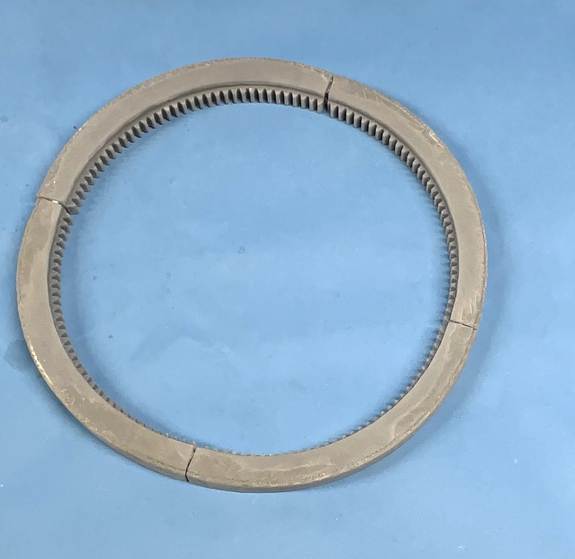
The ring gear assembly test was successful. I pushed the segments together, but not fully seated. There was some warpage with the curve of each segment tightening. I've given up the thoughts of having this beast actually rotate since all the cutaways would be out of sync, so if it's a little out of round, I can probably live with that. And like an idiot I sanded both running surfaces before assembling and sanded off those nice raised lettering that identified the assembly sequence. I was still able to puzzle it together by looking how the gear teeth were split. None were segmented in the same way making them unique.
The gun slide was another thing entirely. While the print was successful (sort of) it still warped a lot. Both halves warped away from the jointing surface at each end. I thinned the slide sleeve that was to accept the gun to much. I did this so it would slip into the slots on the glacis plate on the gun house. So it kind of fell apart when I post-cured it. I screwed it together tightly using the two screws by design and another 1/4-20 bolt and nut through the trunnion hole.
You can see the warp on the right side. That one doesn't bother me becasue that hexagonal shape is going to slip into a corresponding hole in the breach block.
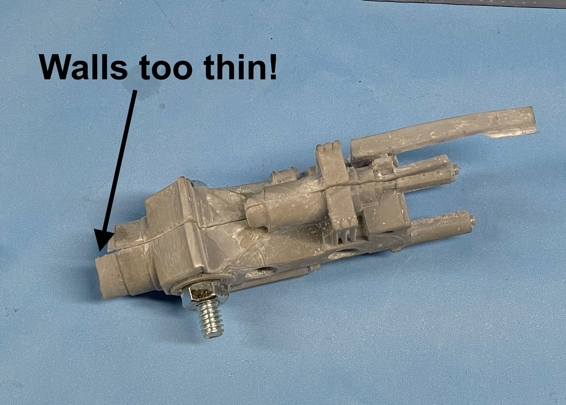
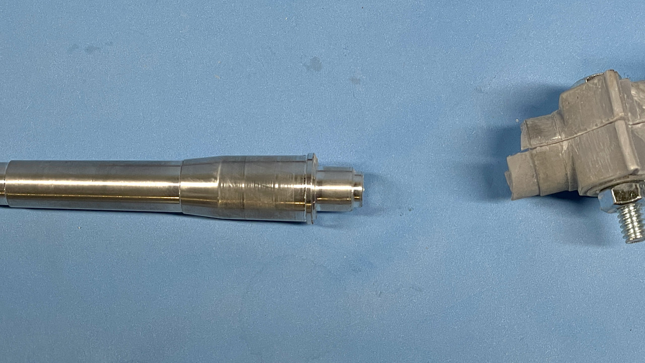
This sleeve problem required a more drastic solution. I turned down the tail on one of th guns to 7/16", narrowed the outer walls a bit more so the sleeve with fit through the .457" opening in the gun house and still give me more wall thickness so it would be stable.
I wasn't sure I could chuck the tapered barrel into my little Taig micro-lathe. The spindle through-hole is not large enough to accept the hole barrel up to the parallel part at the slide area, but i was able to center it with the four-jaw independent chuck and use a steady rest to support the long overhanging part. I got the concentricity within a couple thou. I wrapped the chuck area with some adhesive label paper to protect the finished surface. I was able to successfully change the diameter. If my lathe was a little bit longer I could further drill out the bore, but it ain't, so I won't.
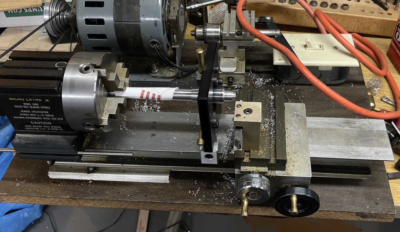
Here's the turned down barrel. I'm not worried about the wear that the steady rest applied to the slide area. I will work that out. Actually the slide wear line go fore and aft not radially.
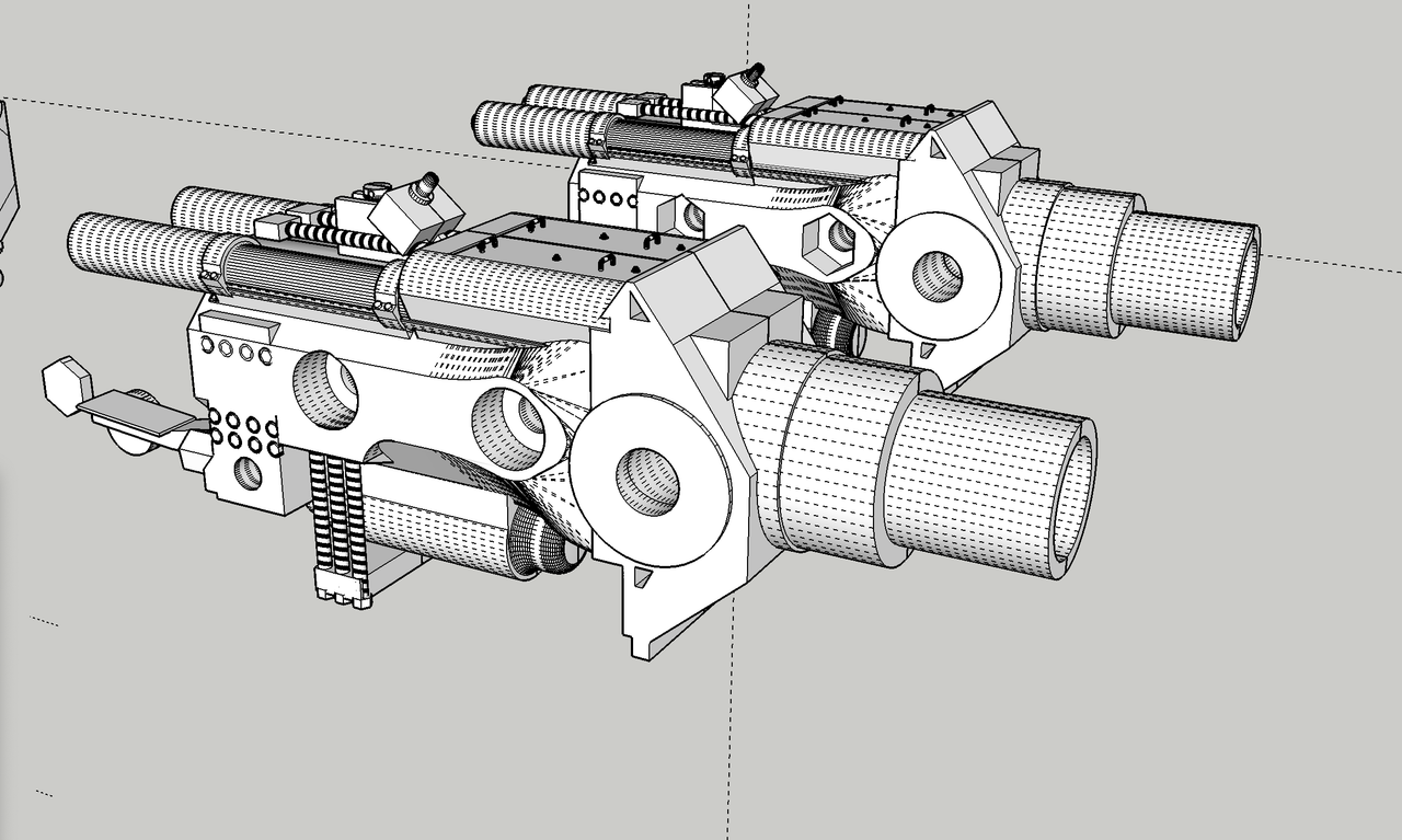
Here's the reviseed design. The new design also gave me a chance to fix some drawing errors that were causing some print errors. You can see the thicker walls around the barrel entrance.
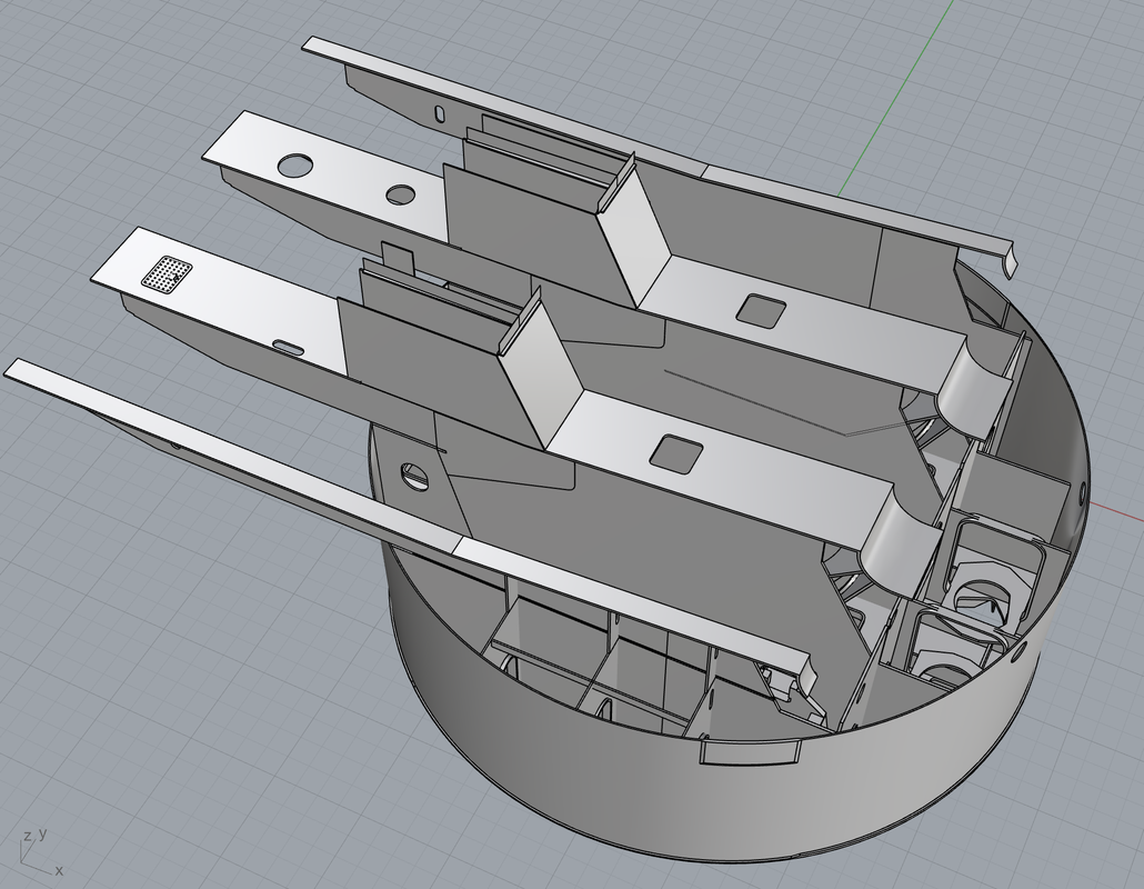
Jim Palmer, one of my faithful followers, has provided me some exceptional drawings (not SketchUp) based on actual engineering drawings of some of the critical structural areas that are very ambiguous on the illustrations that I have. He's going to get me some dimensions to make these more usable to me. One of the big "AHA's" was the edges of the gun girders form the partition plates in the pan deck. I can make this modification. I just need some measurements to firm up the final shapes.
I haven't re-printed the revised gun girders so I can simply change the notches for the styrene plates so they'll be the full depth.
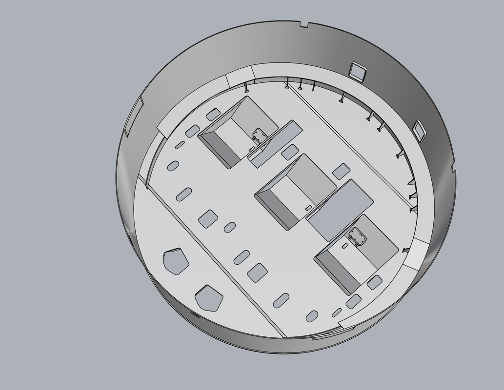
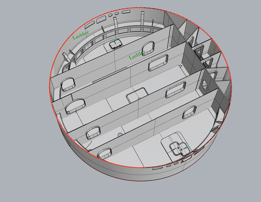
Here also detailed the pan deck floor showing the exactly location of the gun pits and the various hatches used to get from one place to another. You can only actually enter the rotating parts of the turret in two places: the hatches underneath the gun house from the main deck, or entry through the powder flats at the turret bottom. All other access is by vertical ladders and quite small hatches. For these reasons I'm seriously wondering if I'm going to physically be able to go through all these spaces. Noticce the two outer access hatches are actually in the gun pits themselves.
What's even worse is the electric deck.
The Electric Deck is fully partitioned and you can't get from one partition to the other. You must go either up or down and then across. It's like the Super Mario Brothers game. Luckily, I have done nothing on this deck except the outer walls so I didn't waste any effort. And then there's "how to show this interior?" There are four work stations in these partitions: one person manning the manual training (traverse) station, and one each manning the manual pointing (elevation) stations. It must have been pretty longer in those claustrophbic work stations in the bowels of the turret. All of this deck and the pan deck rotations with the gun house and the guns. When you get to the projectile decks, the outer portion is fixed. The next ring with the projectile hoists rotates with the turret sicne the hoist chases are fixed in their position to the gun compartments, and the inner ring is rotated independently with it's own power system and circlar rack and pinions... sort of miniaturized version that rotates the turret itself.
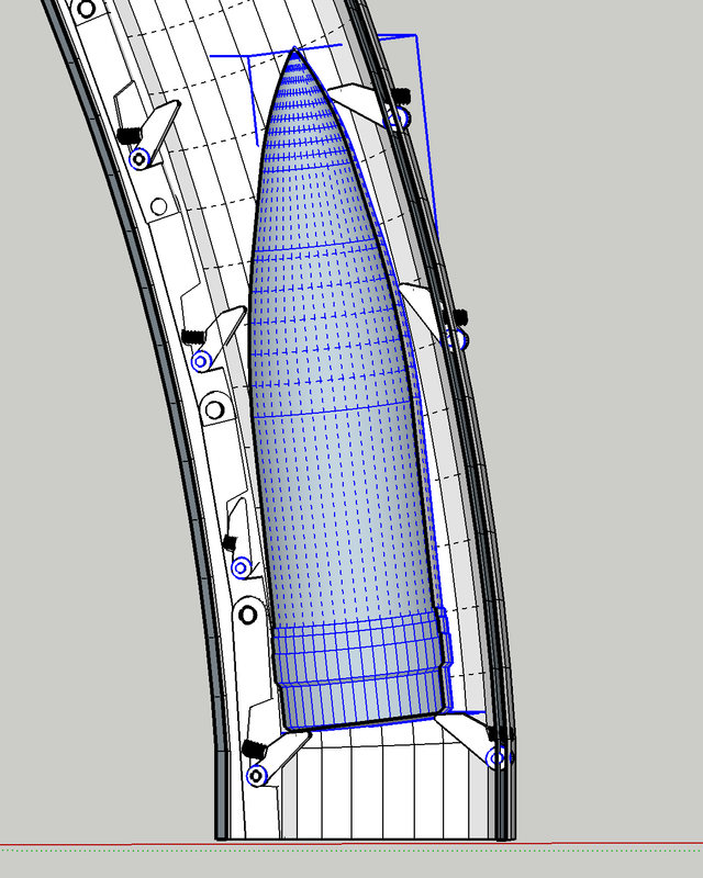
I finally figured out how the projectile hoist actually works. It was somewhat difficult (for me) to puzzle it out since I was expecting an elevator arrangement like the powder hoist. But when you think about it, this wouldn't be easy to do since the cradle that accepts the projecile is open at the top and there's no cable pulling anything up.
Instead the mechanism consists of a moving rod that has spring-loaded pawls that engage under the forward side of the projectile's bottom, and another series of spring-loaded pawls that pop out of the projectile hoist chase opposite to the moving rod.
The moving rod is stroked up and dow by a hydraulic cylinder (for those so inclined, the first part of this sentence did not talk about what you might have thought it was talking about). When the projectile is pulled into the hosit base via the par-buckling rope it passes through two spring loaded doors preventing the projectile from re-entering the projectile handling area. The hoist rod starts moving up with the spring-loaded pawl extended and it hooks under the projectile lifting it up the length of the piston stroke. As it reaches the top of the stroke the projectile has been passing by the pawl on the oppositie wall which pops out beneath the other side of the projectile's bottom preventing it from falling back. The moving rod retracts downwards bringing the next pawl (retracte) along side the projectile where it pops out at the bottom grabbing the projectile and lifiting it the next stroke. This continues until the projectile enters the cradle which also has a pawl that snaps out grabbing the projectile and preventing it from falling back. The projectile is stable in this position and ready for loading the gun.
With this method, you can have more than one projectile on the lift at the same time. In fact, in order to load the gun every 30 seconds, you could not wait for a projectile to rise four decks and be ready to load. While not an actual drawing, this is my interpretation of how the pawls interact to move the projectile from the projectile flat to the cradle. The moving track is on the left. The pawls on the right are somehow fastened in pockets in the projectile hoist chase wall. That detail is not essential to understand the mechanics.
