SEARCH FINESCALE.COM

Enter keywords or a search phrase below:

US Navy 5"38 Mark 28 Twin Turret in 1/35 Scale with Full Cutaway down to the Magazines

9872 views
62 replies
1 rating 2 rating 3 rating 4 rating 5 rating
  • Member since
    March 2012
  • From: Louisville, KY
US Navy 5"38 Mark 28 Twin Turret in 1/35 Scale with Full Cutaway down to the Magazines
Posted by Builder 2010 on Saturday, July 22, 2023 9:48 AM

After the success of building the 1/72 scale 16" Turret from Keel to Gunhouse, the Battleship New Jersey Museum and Memorial has agreed to permanently display a similar rendition of the 5"38 Mark 28 Twin-Gun, Multipurpose Gun found on almost every WW2 (and later) ship.

To refresh your memory, here’s the 16" project as presented to the ship.


When Takom came out with the 1/35 kit of the 5" Twin turret I thought just maybe doing it again.


I contacted Ryan Syzmanski, the Big J’s curator, and asked if he would like to have a companion to the 16" turret now on permanent display in the Ship’s ward room. He immediately responded that it would be a good addition.

I’d been collecting reference information about the twin turrets (and the 40mm quads) for years along with my 16" research, but this past week got into full swing. That includes reading the entire service manual of the turret. Service manuals give you some line drawings that are exceptional value.

I had a lot of lessons learned with the 16" project and hope to apply them on this build. I’ve also had in the back of my mind that other muesum ships may want similar models. As far as I know, no one had ever created an Iowa turret complex like the one I built and have similar thoughts about the 5"38s based on my internet searches.

One of the first things I learned is don’t get too far into the design until you have the model in hand. I had a terrible time getting the main gun alignment with the Iowa turret since it was dependent on the openings in the front face of the plastic gun house regardless of what the plans showed. The Takom kit comes with the metal barrels included so I won’t have to special order that.

I imported relevant drawings into SketchUp 2023 and scaled them based on the actual sizes given on the one drawing that shows some critical dimensions. With that I could be secure in the knowledge that all the drawings were agreeing with each other. As with the Iowa, most of the drawings had no dimensions so it was all about good estimating.


I’ve already done too much desiging the subframe that supports the two pairs of gun mounts. For example: Just looking at the box art I see that the training buffer (device to stop rotation before the turret hits something it shouldn’t) is already attached to the exterior of the turret. I don’t see that detail like that on the battleship turrets. So I have to do more research. While the guns were essentially the same in all of its applications, there were slight differences. I’m doing the battleship version. Another example is the base ring. I can tell already that the box art is not a battlehsip application.

While my drawings show pretty good renditions of the floor plans of the turret, I have no idea how this relates to the Takom model. My main reason for doing the drawing was to ensure that my 3D printer could produce it in a single part. I just fits.

This is the subframe.


And he it is tentatively put on the 3D printer slice (ChiTuBox). I am not printing this! I don’t know if it’s correct or not until I get the model. My LHS has ordered another kit since he sold his last one.

Here’s the test piece on the slicer. The red areas are out of the print range, but are just small parts of the raft that won’t matter. That said, every other angle to which I rotate the object puts some part of the actual part out of the print range. So it JUST FITS. Convenient!


I have the Takom Apache to build so this project may or may not get started first. Depends on when I receive the Takom 5" turret model. I’ll start the Apache and put it aside when the turret arrives. Building for the battleship takes precedent over models for my own collection.

  • Member since
    May 2009
  • From: Poland
Posted by Pawel on Saturday, July 22, 2023 2:17 PM

Unbelievable! He's doing it again! I'll be watching!

Good luck!

Paweł

All comments and critique welcomed. Thanks for your honest opinions!

www.vietnam.net.pl

  • Member since
    March 2012
  • From: Louisville, KY
Posted by Builder 2010 on Friday, July 28, 2023 1:58 PM

Yessir! I will be doing it again, only this time with a twist. When my LHS told me the Takom model was in, I went to pick it up, only to find that they had ordered the 16" turret. We all know how that turned out. And... the 5" turret is out of stock...EVERYWHERE! So what to do?

Since I've already told the ship I'm building this, I feel committed. So now I've decided to scratch-build the entire thing. All that this requires is the gun house shell, the ring base, Officer's cupola and the guns themselves. It's the guns that I'm missing most since they were metal turned barrels included in the kit. 

As I noted, the kit's based on the Mark 38 destroyer version, not the Mark 28 Iowa-class version. That would have required some kitbashing. Now I'm no longer constrained by the kit's inaccuracies or it's scale. I can choose whatever scale I want. I could find a machine shop in town that could do the barrels for me, or I could 3D print them. Since that will cost be basically nothing, I will go that route first. If it doesn't work, I can go to plan B with a machined barrel. Since the kit included these parts, I suspect finding the barrels themselves on the aftermarket will be difficult.

My little Taig lathe could turn the barrels, but it's not really suited to turn long tapers. Ideally, the barrels should be produced on a Swiss-type screw machine that are designed to produce long, slender objects.

So the game is afoot.

I als need to get some diamond plate for the gun house flooring panels. Even this could be 3D printed depending on the scale I choose.

Stay tuned... this could be a little rough.

  • Member since
    April 2003
  • From: USA
Posted by keavdog on Friday, July 28, 2023 4:01 PM

Oh boy!  Given your last gun build the turret will be the easy part for you!

Kit is available on Amazon if you want to go that way

https://www.amazon.com/TAKOM-U-S-Navy-Barrels-Plastic-TKO2146/dp/B09FSQ1FML


Thanks,

John

  • Member since
    October 2019
  • From: New Braunfels, Texas
Posted by Tanker-Builder on Saturday, July 29, 2023 3:10 PM

Hi!

 You are right! The Boxart shows the gun as seen on the o-1 deck unit

  • Member since
    March 2012
  • From: Louisville, KY
Posted by Builder 2010 on Monday, July 31, 2023 10:48 AM

With my decision to go cold turkey and do it all from sratch, design work has begun in earnest. While I don't have fully dimensioned drawings for everything, I found another manual that fully details every aspect of the twin turrets and gave me enough specifics about the Mark 28 so I can get many important things right. As a result, I have fully TYdrawn to exact specifications the armored gun house.

The Mark 28's armor thickness was 2". That's 0.040" in 1:48, so using that sheet thickness, not only is very workable, but is correct scale thickness. I didn't have the luxury with the big gun. In 1:72, the 1" wall partitions would have been 0.010" sheet which is too thin to be practical. On the Mark 28, the armor plates are attached to internal angle braces by countersunk bolts and rivets. I was incorrect earlier when I said it was welded. There are a few exposed bolts where the floor framing members tie into the walls. Also I'm striking out finding pre-made 14" drop rungs wirh bolt rings. I already printed them for the big gun and can use the same drawing scaled up to make them for this one. I they held together at 1:72, they'll do well at 1:48.

I have actual diameter measures of the base ring and training gear so I chose to start here. I also have a section drawing across the ring which I scaled. I placed the profile on a ring that corresponded to the base's overall shape.

Using the "FOLLOW ME" tool (select the ring, select FOLLOW ME and then select the profile) and the program magically lathes the profile around the circumference. The counterbore and the land represent the lateral and tapered roller bearings on which the rotating mass revolves. I'm not going to detail the bearing. Unlike the monsters in the big gun, these would be almost indistinguishable in 1:48.

I learned how to do internal ring gears in building the big gun, but I'll quickly review it. I have an add-in to make volute gears. You enter the number of teeth, the pressure angle, and the pitch circle radius and Voila!, it draws a gear as a separate item. It only draws external pinion gears, not internal ring gears. I was able to find the exact number of teeth and the pitch circle diameter of the Mark 28's, and with those numbers drew the external gear. I also had the outside diameter of the gear which was the inside diameter of the bottom counterbore. I centered the external gear over a filled circle of the outer diameter and INTERSECTED the faces. I now had a drawing of a filled circle with line drawing of the internal teeth inscribed on it. I delected the inside, and then PUSH-PULLED the remainder to the height of the full gear as shown on my scaled cutaway drawings. All in all it took as long to do it as to write this paragraph.

I inserted the completed gear into the base ring.

The last things to do was add the reinforcing ribs and the nut/bolt/washer N/B/W images on the ring flange. I made one rib based on profile drawings and counted the number on the prototype. Looked like there we 32 of them. In SU, you use the rotation tool, with the center placed in the ring's center. You move/copy a single rib 11.2 degrees corresponding to the gap between them, and then key *31, the program copies the rest equally around the ring. It's "31" not "32" because you've already copied one.

I did the same thing with the N/B/Ws making a set of two and copying them around the ring.

Because the geometry is so regular and one dimensional, I am going to attmpt print the entire part directly on the build plate. It will all depend on the build plate's ability to hold onto the part during the formation of the base perimeter layers which have the greatest amount of surface area. I those layers stay put, the rest of the print will be no problem. I will only take about 20 minutes to print, so I won't have long to wait.

If I was printing this part in 1/35 instead of 1/48, it would not fit this way and would have to tilted. Without tilting, there are no supports to deal with and details come out perfectly.

With accurate overall gun house enclosure dimensions and wall thicknesses, I was able to adjust my frame drawing so it was exact. If I was using the kit, I would have to wait until I could meassure it directly before finalizing the frame. I also had the exact diameter of the ring that connects the rotating to the fixed structure and attached it to the frame. I moved the training buffer inboard of the frame extremis to conform to the Mark 28 configuration.

Again, in 1:48, this fits the printer nicely and will be a single part. This ensures perfect alignment of this important structure.


Last part I detailed was another critical one; the guns. I had good profile drawings so I was able to create the correct straight and tapered portions. I added some rifling. There are 40 lands, but did not add any twist. You're only going to visualize the very outer edges of it. The outer lip of the muzzle is rounded. I will do this as a post-print operation.

I'm trying two print schemes: Directly on the build plate and raised off. Since it's so symetrical, it can be printed straight up with no overhangs or islands. While it should print directly, I'm thinking that raising it will facilitate liquid resin draining from the bore.

We'll see which one wins. Unlike the ring gear which had little height, the guns will take over 6 hours to print. In LCD resin printing height is the key varialble in print time.

I found excellent elevation views of the all-important gun mount castings and will tackle them next. Also found good information about the complicated projectile hoists.

I actually need more information about the floor plan of the projectile handling room and the powder and projectile magazines on the 3rd deck.

  • Member since
    November 2005
  • From: Formerly Bryan, now Arlington, Texas
Posted by CapnMac82 on Monday, July 31, 2023 1:50 PM

Builder 2010
If I was printing this part in 1/35 instead of 1/48

Ah, I wondered about the scale change.

It occurs to me that, were a person to cast a clear gun house, but fill it with the full crew (and simplified "innards"), this would make Ryan more than passing happy, as he fields a lot of questions on just how many people are wanted in a gun mount.

This is likely a more reasonable task than the 16" mount, given the difference between WWII's 80-odd versus the 80's manning with around 60 (not that casting 60 figures would be a simple task)

This would be a simpler situation with a 5" mount.  It would also allow getting some use out of "test prints" too.

It's just a thought, if one inspired by Ryan's own words.

  • Member since
    March 2012
  • From: Louisville, KY
Posted by Builder 2010 on Tuesday, August 1, 2023 3:47 PM

It shouldn't be too hard to populate the gun mount in 1:48. I'm going to do a selective cutaway rather than transparent for reasons too numerous to mention. Suffice it to say, I'm not very good at transparent parts. There's always a blemish somewhere. 

I've started producing parts with varying success. My first part was the base ring printed flat on the build plate. For some reason, the training gear teeth started to form and then just stopped. A few layers were laid down nice and parallel, but then nothing. I also had some slight delamination. The delamination I could fix, but the gear teeth would be a bit trickier. I could print the gear separately flat on the plate and insert it. Meanwhile, I've set it up at an angle and will try again before going with the separate gear approach.

Next print was the main frame. Strangely, one set of supports failed causing one of the frame's lower extensions to fail. I changed the supports in the slicer and tried again. Here's attempt #1 compared to attempt #2 which was clearly worse. 

There's a silver lining. The arm extensions are mirror images of each other. By surgically removing the bad arm from #1, I was able to graft the good arm from #2. With some thick CA followed by Bondic UV resin, the graft is invisible and strong. The Bondic is the same chemistry as the UV printing resin and when applied to UV parts welds them. Only caveat is the UV curing light must be able to reach the Bondic so it can be used on blind glue joints. Otherwise, it's essential in your UV printing tool box. It cures in seconds!

Here's the removal of the bad arm.

Here's the part ready for the graft. I broke apart #2 to better expose the arm for amputation. I then trimmed the end properly in a miter box with razor saw so the end was square.

I used the CA to stabilize the part (with accelerator) and then used the Bondic to fill all the gaps.

And after sanding, the part, when painted will show no evidence of being "Frankensteined"... Just made a new verb.

Here are the remains of #2. It served well and saved me a bunch of resin. Resin is not cheap, about $40 a liter. I never throw away rejects and have used them many times to provide repair pieces. I'm creating two boxes... "good parts" and "bad parts". Often it's about 3:1 bad to good. 3D printing is an art with a scientific underpinning. I thought I had figured out the failure mode on #2, but the results were worse. The failure still started in the same region some something was going on there. Since I now have a good part, I'm not going to worry about it any longer.

Right now the guns are on the printer and will come off around 7:00 tonight. The fit of the frame ring into the base was very tight. I may have to chain that diameter on the recess a tad so it slips in. They were both created by the same circle so their diameters are exactly the same on the drawing. However, the printing process enlarges parts very slightly, so the holes gets smaller and the ring bigger by a few thousandths each. What was a slip fit is now a no-fit. It's the reverse with laser cutting. I you cut a window opening and the window frame with the same dimension. The opening grows bigger and the frame smaller since the laser cutting beam has some kerf width, just like any saw only much tinier.

I almost have the gun mounts ready for printing. I drew them over my profile drawing. My first attempt had the cross bracing in the front on the wrong end. I was able to fix it without too much difficulty.

The guns are printing successfully with both setups building straight down.

I redid the ring gear for printing and drew the training worm and pinion. I ended up making the gear with 14 teeth and a pitch radius of 8". It meshed well. Nothing is going to have to move and everything is printed as a solid obect.

Here are the finished drawings of the engine mounts. I saw that there were bolts holding them down so I added those and added bolts to the Trunnion Caps (being printed as a separate item so so the guns can be installed. The bosses jutting out from the side are where all the sighting gear is attached

I did have sufficient drawing to build the training worm and pinion with reasonable fidelity. The worm is driven by a drive shaft from the hydraulics. Manual drive is selected through a series of clutches, but still enters the worm via the same shaft. I'm probably going to use metal shafting for all of them... and there are a ton.

Front view:

And reverse view:

Here's how the training gearing is going on the printer. As usual, I never print just one. It cost about 20 cents worth of resin for each one and it doesn't add any printing time. If this was a filament additive machine, the more parts you have up on the machine the slower it is since it must draw each line like a plotter, versus the resin machines that expose an entire layer at once, like a laser printer. I group them close together to facilitate popping them off my flexible build plate.

  • Member since
    March 2012
  • From: Louisville, KY
Posted by Builder 2010 on Tuesday, August 1, 2023 5:07 PM

Guns just came off printer. I was correct. The resin didn't drain well from the one that was printed directly on the plate and the bore is narrower at the plate end due to "elephant footing". Elephant footing is the phenomenom created when the part widens at the first five base layers. These are generally exposed at 1 minute instead of 2.5 seconds. The long exposure is used to create the "raft" that holds the model to the build plate. You really want this layer fully hardened so it sticks well. When you put a part directly on the plate, that 1 minute exposuse/layer causes those five layers to widen also. They become wider because the long exposure leaks from the pixels that are to be illuminated to neighboring ones. 

The gun with the support's bores are parallel throughout the print. They're in the Ultrasonic cleaner now. I will take pictures as I clean them up. I just put the modified base on the printer. It will be done around 10 p.m. Nice thing about printing... I generally like to print overnight so it's working when I'm sleeping. Unlike string printing where you have to keep an eye on a clogged nozzle, with resin printing, when the part is right and mounted right, and the printer is lined out, it will work without any attention.

From my cursory inspection the guns show no imperfections and should look great.

  • Member since
    March 2012
  • From: Louisville, KY
Posted by Builder 2010 on Tuesday, August 1, 2023 5:26 PM

After cleaning you can see the difference between the non-support, direct print one on the left and the one with the supports that raised it a bit off the build plate.

Besides that slight difference in the bore at the breach end, the rest of the print is perfect and not different between the two. They're getting post-cured now and only a very little cleanup will be required to create some beautiful guns. There are no layer lines and they ARE NOT warped that I can see. I'm quite pleased. I will not have to get machined barrels.

Once they're cured, I will take a diameter reading at the slide end and use that number to draw the bore in the slide, plus some clearance tolerance. I don't want a press fit. If I wanted to, I could make the guns able to recoil, but I probably won't. This will be enclosed in Plexiglass and never be touched to play with it.

Onward and upward! 

  • Member since
    March 2012
  • From: Louisville, KY
Posted by Builder 2010 on Friday, August 4, 2023 10:17 AM

I spent almost an hour the other day writing the post with lots of images. Unfortunately, I let it sit too long before uploading and my computer reloaded the website "Because it takes too much memory" and the whole deal was lost. And now I have to do it again. I came up with a scheme to copy after writing so if anything happens, I just paste it and am good to go. This time I forgot to do that.

So here goes.

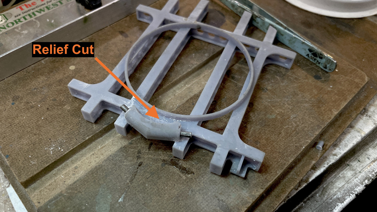
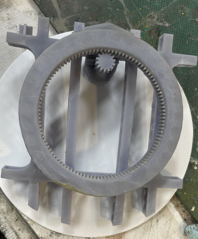
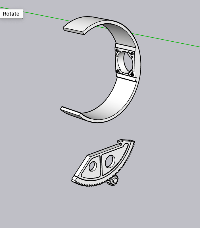
The reprinted ring gear was excellent, one slight area needing fixing. I fixed with Bondic. It fits the mounting ring on the frame well and the two can rotate. The real one has retaining clips that grip under the training gear and I'm going to duplicate so the turret will be positionable. I found that the Training Buffer interfered with the ribs on the stand, I surgically removed the offending material. I found another drawing of the buffer and it looks like the back is relieved for the same reason.

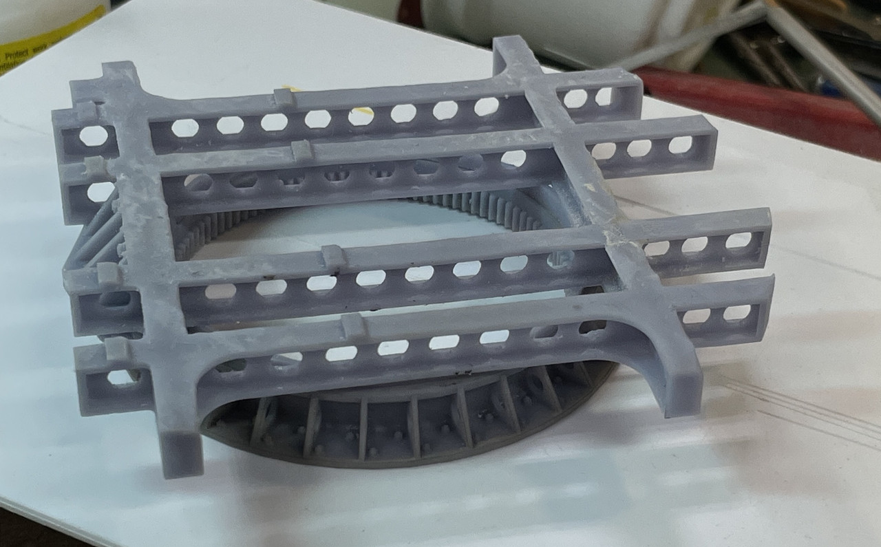
The mod: I also replaced the printed plungers with steel. One didn't form right and after replacing it, I did the other to match.

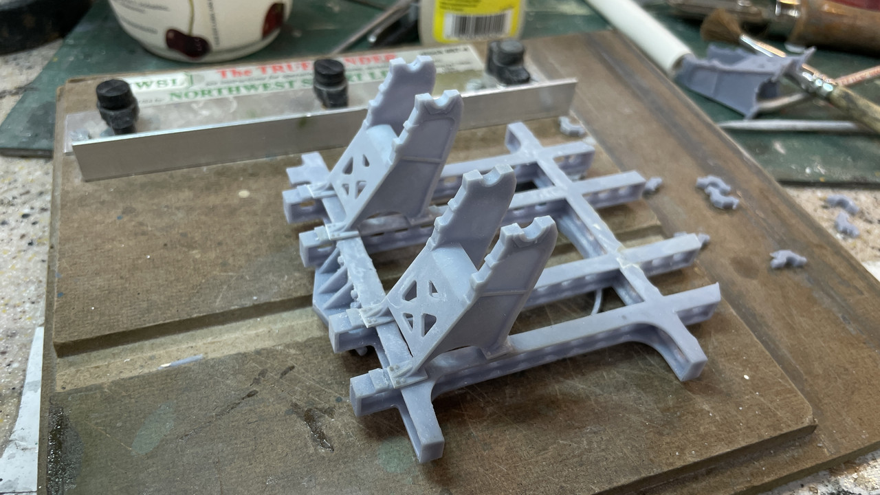
The gun mounts printed well. I always make more than I need and one set had a fatal defect. Didn't matter, I had three more and only need two. As printed off the machine.

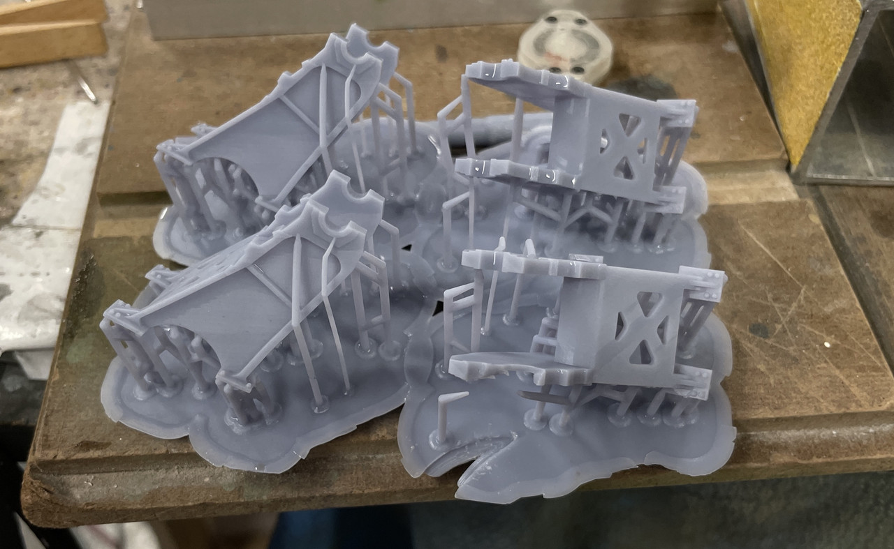
Finished set: Not glued, just set in place.

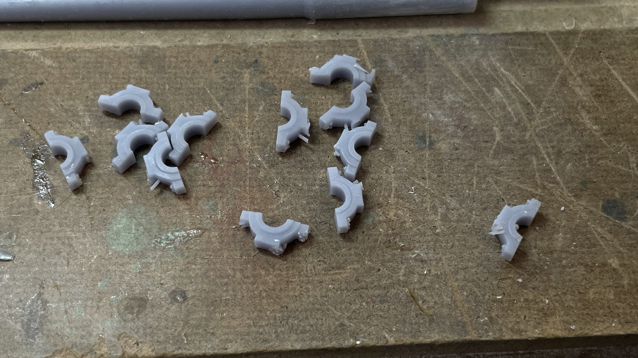
Printed a gaggle of trunnion caps. I erred. I put two bolts on each side. There is only one... Not going to worry about it.

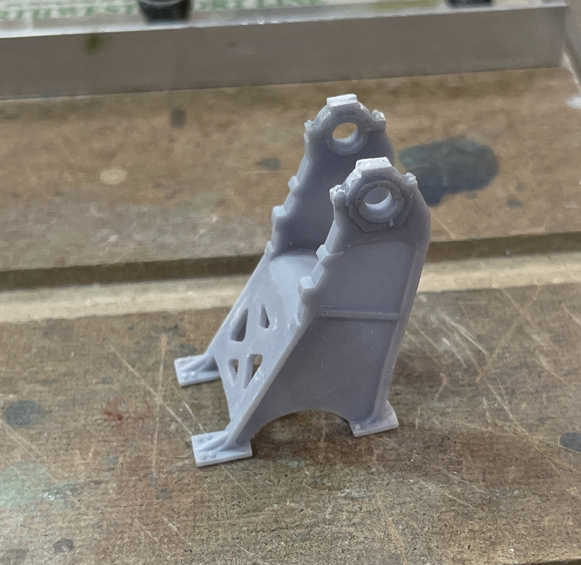
Here's the caps placed on the mount. Again... not glued. Can't do that until the guns are in place.

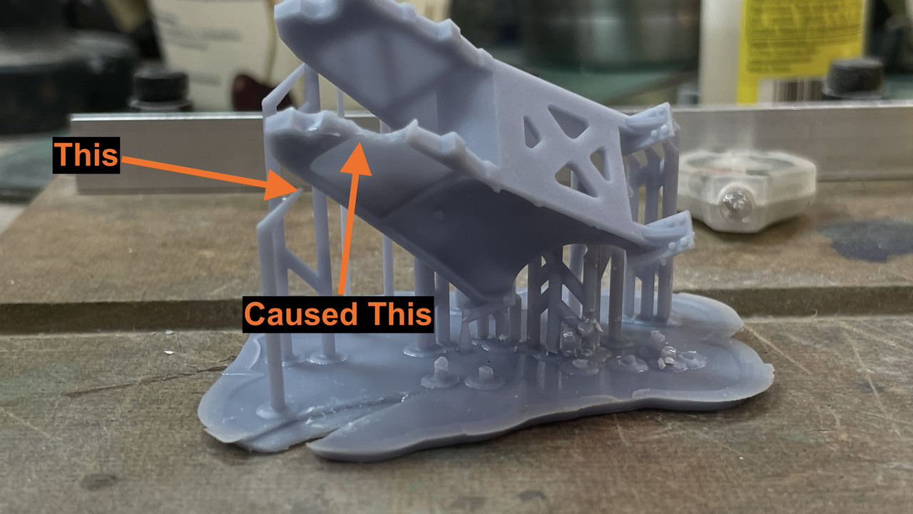
Here's the one that failed. And you can see why. That support failed. When the support fails it usually leads to a local or catastrophic failure depending on how strategic the support is.

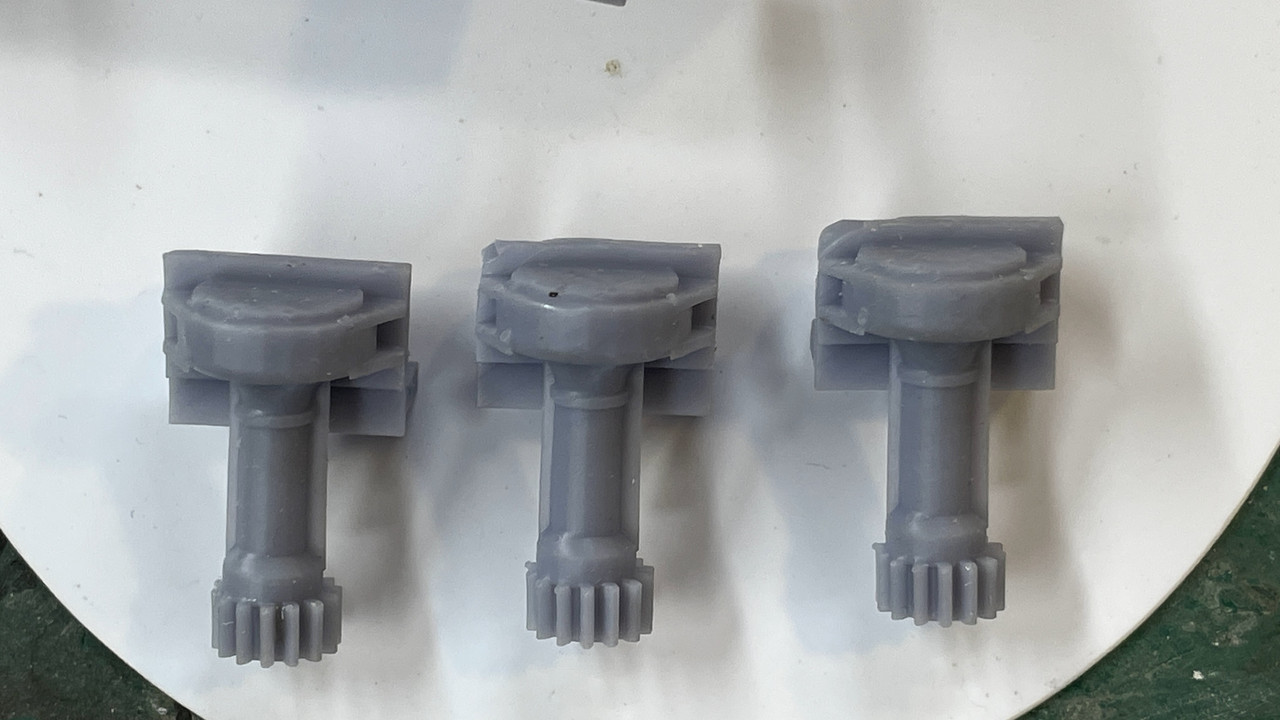
I also printed successfully, three out of four Training Worm/pinion assemblies. Only need one. This one was also a support failure, but of the more catastrophic variety. It left the partially formed part stuck to the FEP film at the vat's bottom. The new version of Elegoo's FEP film is very forgiving. Stuck parts pop off with no damage to the film. I can run for months without having to replace the film ... a 20 minute job. Looks like something that didn't make it through the Star Trek transporter too well...

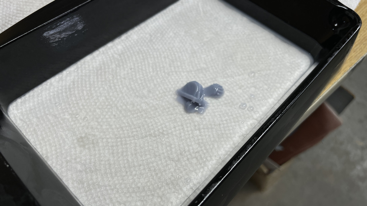
Here are the good ones. Even among these there are some that are better than others. Always make more than you need!

Here's the trial fit top view. Part has NOT YET been finish sanded and you can see by the support marks on the top.

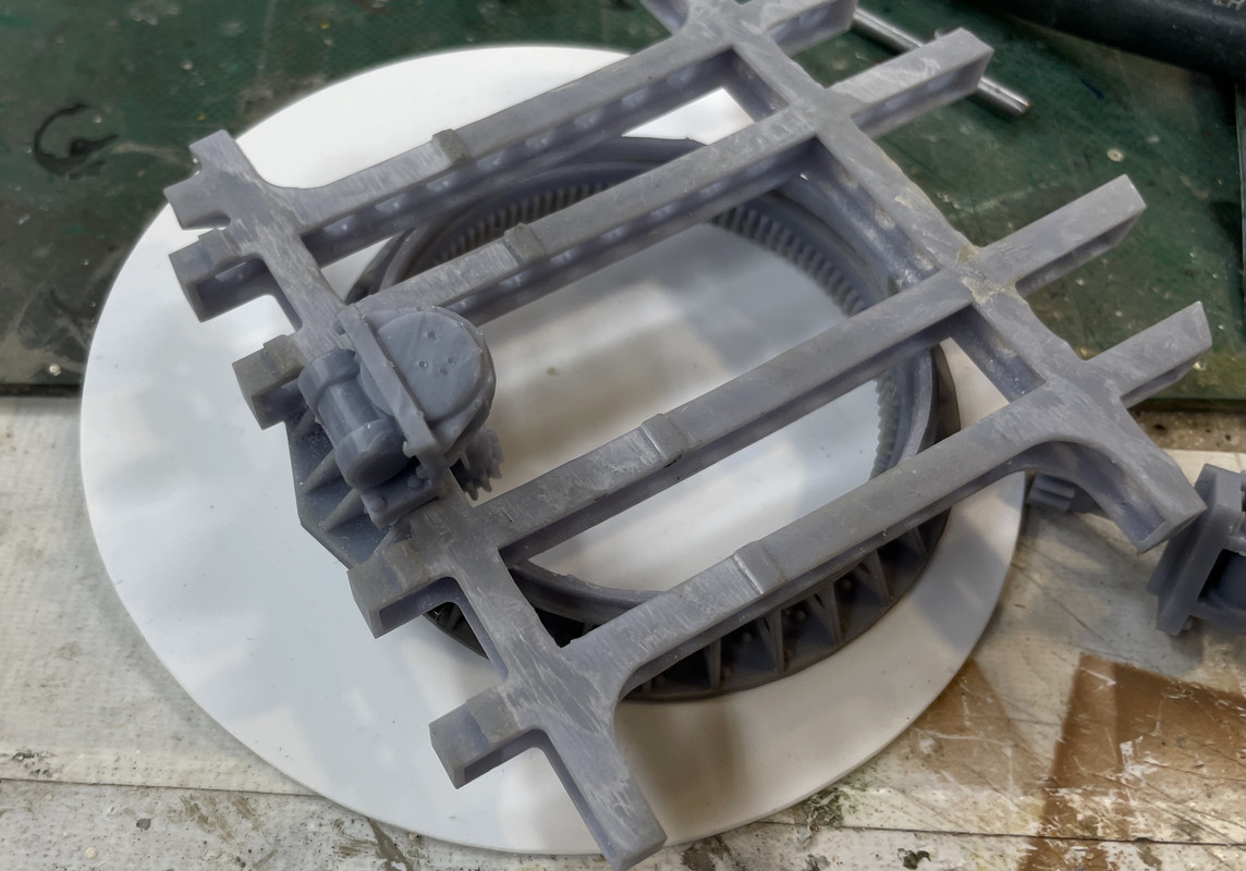
And the bottom view showing the pinion meshed with the training gear.

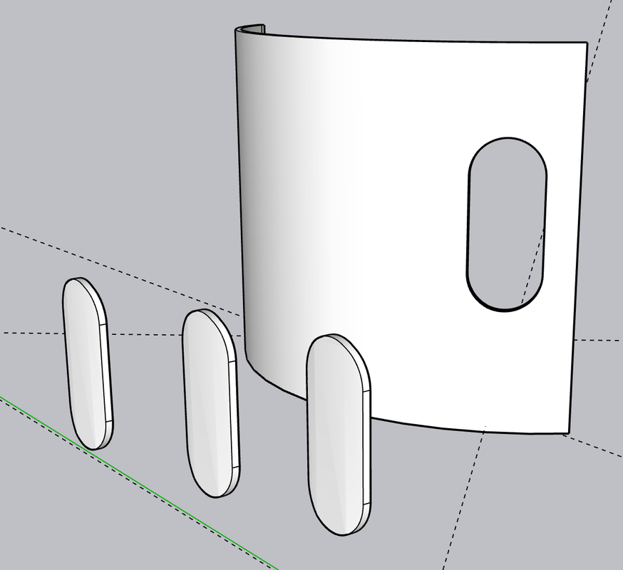
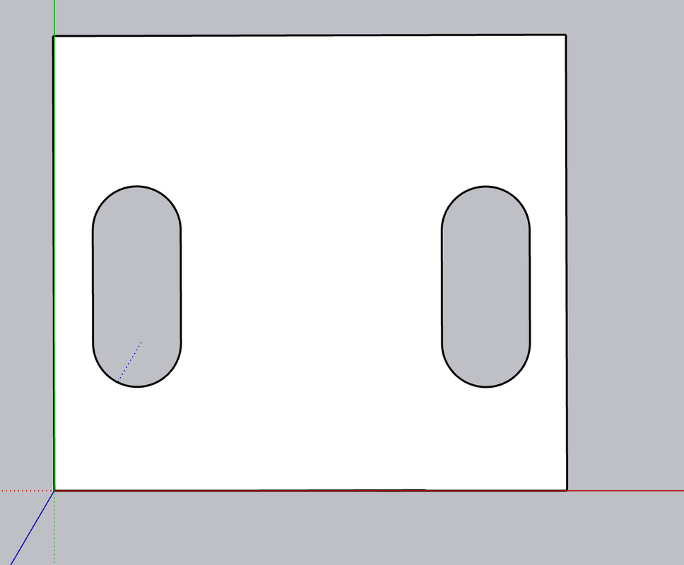
That's all the parts that are drawn to the point of being able to print. There's a whole lot more going on in the design department. I finished the gun shield and elevating sector gear, but both have to wait until the gun proper is finished. There are some brackets that engage in the gun that can't be finalized until gun is done. I also started delineating the armor housing with the curved back plate. I'm going print the hatches with their hinging, but the curved wall will be 0.040" styrene. Technically, the armor on the this ship's secondary batteries are 2.5" which is 0.050" in scale. I may laminate 0.040 and 0.010 to make fifty. Laminating also helps maintain the curvature. I had to extrapolate the lateral position of the hatchways due to the curvature of the image. I then flattened the curved piece using SU's "UNWRAP & FLATTEN" facility. 

The gear teeth are finer on the prototype, but at 1:48, if they're too fine, you won't see them.

Here's some WIP shots of the rear panel. I'm not sure if the hatch is curved. It too a while to create the curve using a copy of the wall section to cut the inner and outer faces. If flat, that's much easier to do in styren. In addition to the crew hatch, there are four others for the cartridge discharge chutes.

Here's the wall flattened as a test.

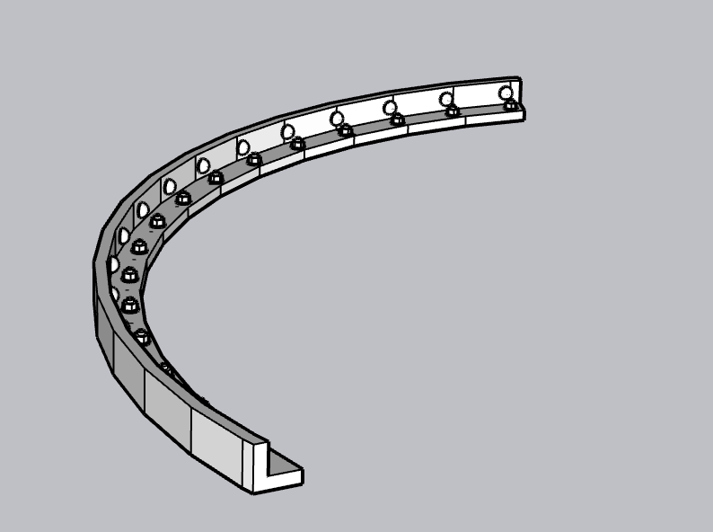
There are angle bars that attach all of armor panels to shape the gun house. I'm going to 3d print these with fasteners. My shape isn't exactly right as I've ssen on some video footage. Don't know how anal I'm going to be about it. The fastener pattern's probably not right also other than it's a combination of rivets and bolts.

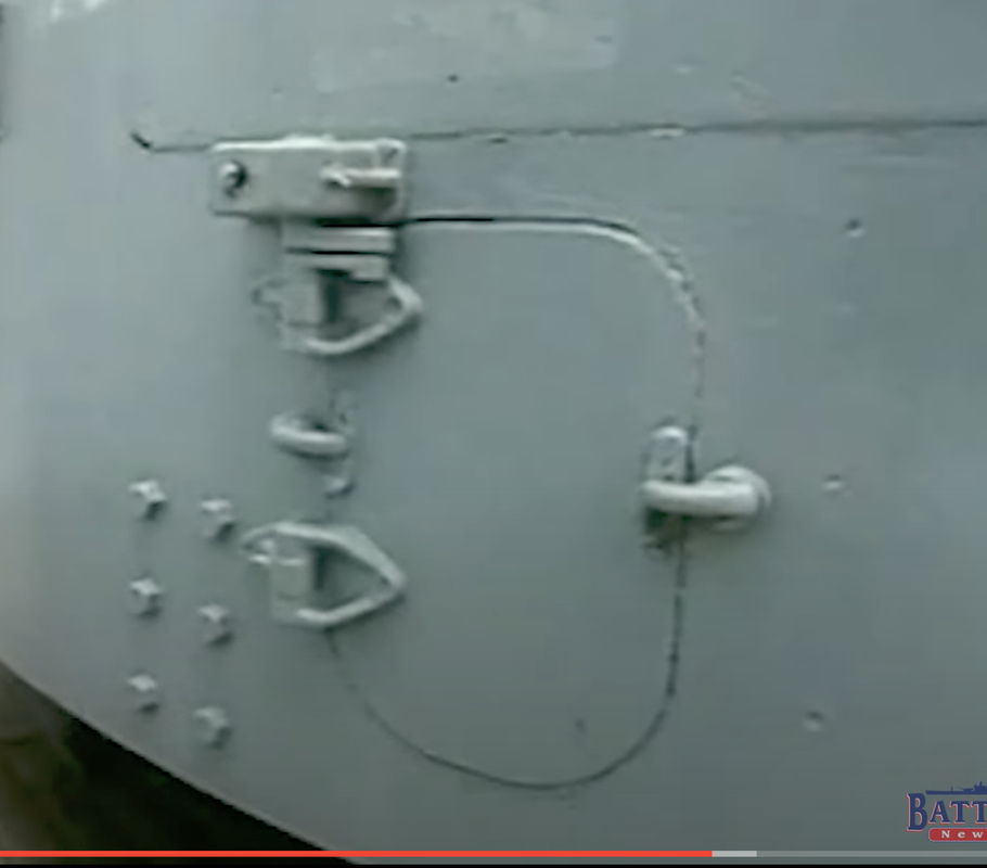
Here's the actual back do. I'll print the foot rungs too. Hatch looks flat. This is the lower discharge port. The six bolts to its left are those that are holding the housing to the longitudinal frame rail.

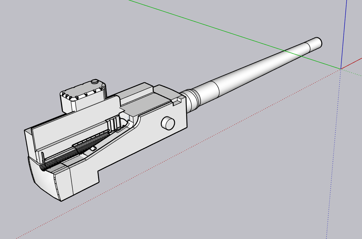
Now the gun. The geometry is a killer for me! I don't have any drawing of the parts separated, e.g., slide, housing, etc. I was very difficult for me to visualize just what parts move during recoil and what parts are fixed. When you watch videos of the guns firing, the recoil is so fast you can't stop it when recoiled. I suppost you could copy the video and do some frame-by-frame editing, but my bet is that it would highly blurred.

The real of the housing is curved in two directions... sort of part of sphere. I first had it curved only in the vertical direction, but realized it was wrong. To do compound curves in SU, I find it easiest to create a cutting too of the right shape and use it to shape the object. In this case, I created a segment of a sphere and placed it so it would remove the right amount of material.

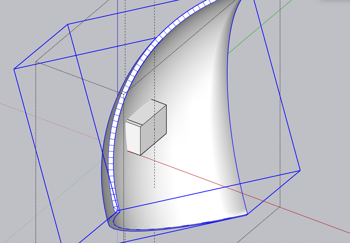
After cutting I grafted the part to the rear of the gun frame and it actually worked out. Still have lot of details to include and am constantly checking that the object is still solid and printable. Last night started working on the rammer hydaulics. I used one of my drawings a as guide only to find it was completely wrong for the reservoir. Found others that were accurate. I spent almost 8 hours yesterday just doing drawings. And I have hours and hours more to go. Taking the day off to go see Openheimer.


  • Member since
    May 2009
  • From: Poland
Posted by Pawel on Friday, August 4, 2023 3:51 PM

Impressive, as always!

Recently I thought... There's actually one more turret you should do, and there are many people interested... I'm talking about the interior of the M60A1 tank turret. I tried to tackle one myself, but the design got too complicated for my computer plus I couldn't resolve some of the dimensional problems...

For now good luck with your twin turret, I'l be watching! Have a nice day!

Paweł

All comments and critique welcomed. Thanks for your honest opinions!

www.vietnam.net.pl

  • Member since
    March 2012
  • From: Louisville, KY
Posted by Builder 2010 on Friday, August 4, 2023 10:57 PM

Thanks Pavel. Maybe... I'm more partial to really big guns, but I'll think about it. Didn't Rye Fields do Abrams with the full interior?

  • Member since
    March 2012
  • From: Louisville, KY
Posted by Builder 2010 on Tuesday, August 8, 2023 2:16 PM

It happened again!!!! I accidentally hit the little "X" in the tab on my Apple Safari browser and closed the very long post I was just about to finish. I lost the whole thing! I broke my own rule that I just created last week: Save the bloody thing periodically so you can replace it if I keep doing this.

Here we go again.

I was able to find FREE deck plans of the USS Missouri in 1950 configuration when it still had all the 5" gun mounts. I was able to load up the main, 2nd, splinter and 3rd decks into SketchUp and display them in full size... you read that right... in SU this file is a ship 887 full length measure. SU doesn't care. I also had profiles of the exterior and center line section. With these I was able to line them all up and finally understand just where everything is going to go. I was also able to size the Ready Ammo Handling Room that supports the turret, and the elusive powder and projectile magazines which do not lie directly under the guns.

The 2nd deck has no gun handling apparatus as does the splinter deck. The splinter deck is a shallow void space to catch any explosive debris before it gets to the delicate spaces below like boilers and magazines. I used the 16" barbettes to register the drawings since the lower decks have overall sizes that are slightly smaller than the main deck due to the ships lines. You can find those plans here: https://archive.org/details/bb63bogp1950/08%20-%20second%20deck.png

When overlaid in correct resgistry I am able to model in full size the paths of the curved powder and projectile hoist trunks. These trunks are designed like this deliberately to mitigate fire from spreading from the upper decks to the magazines.

And I was able to accurately scale the Ready Ammo Room both in area and height by matching to the full size floor plan.

I erred in my design by including a lip around the rooms roof. It is flat.

I also found very good data on the design of the Quick Acting Watertight Door (QWT). It took a while to search through hundreds of images until I hit on a sight that manufactured the style used by our Navy with great head on images on which I could draw the door. I also took screen shots from Ryan's USS New Jersey video "Doors". With these sources I was able to create a very respectable prototype.

Here are the three drawings I used:

Outside:

Inside:

And then the best... the door without the hardware where I could get good fixes on the positioning of the dog pivots.


This was a closeup from Ryan's vid. It shows nicely the roller dogs.

I drew the door in layers and 10X scaling. Sketchup has a trouble with working with curves especially when doing contours in FOLLOW ME. If the segments are too small, it leaves them out and makes holes, whereas when enlarged it fills them complelety. When you shrink the drawing back to original size, the filled areas stay put. I don't know why this is, but it is. To make those bulges, I produced external rounded rectagular shapes and internal ones and bonded them to the drawing on both sides ensuring that there was some material thickness between them. They're printing now, so I know if there was enough material to produce a viable part.

I then produced the frame as a component and finally overlayed the dogs and all their operating links. Some of the links were challenging since they have curves that enable them to clear the other parts.

And here's the finished product showing both sides. The real door has an extension lever on the wheels to give more torque. These would be too frail for printing and I'll attempt to add them with wire. I am attempting to print the doors as a single part. I will see how that works out. I also had to thicken everything. At scale thickness many of these peices would not be viable. The beauty of 1:48 is you can really lay on the detail and have a reasonable chance that it will show up.


As usual, I print multiples. I will probably need at least this many. I'm also contemplating printing the entire rear curved wall of the gun house including the hatchs and details. It might be the easiet way to go if it all fits. Otherwise, I'll print the curved corners with rabbets to seat the styrene walls. That will work to, but won't be as elegant.

Whew! That was a load of stuff. Now I'm goint to check on the print which just finished. Let y'all know how that worked out.

 The prints were marginally successful. All of the complex contours, cranks and arms printed well. The handwheels failed as predicted and the rollers on the ends of the bellcranks didn't form well. They were highlighted in pink, but it wasn't bright pink so I thought they might make it.

At first glance it looked pretty good.

Upon further inspection here's what I saw.

I'll print the handwheels off the model and add them after post-curing. I will also do something to support the roller ends and that should do it. 


  • Member since
    March 2012
  • From: Louisville, KY
Posted by Builder 2010 on Wednesday, August 9, 2023 9:01 AM

The reprint looks good, but useless! The door I drew is not used in the magazines. Jim Slade and Ryan sent me photos and information about the magazine doors. They're not quick acting, but have individual dogs and they're much smaller. I will share and keep the full-size QAWT door since it's used a lot of places onboard ship.

  • Member since
    November 2005
  • From: Formerly Bryan, now Arlington, Texas
Posted by CapnMac82 on Wednesday, August 9, 2023 4:18 PM

Trying to print the moving door hardware separately of the doors probably would answer the printing qustion; bnut not likely be successful overall.

(It would probably want a "casting block" that would want sanding away--that or a holding jig/fixture to install on the doors; or both.)

I've run into both problems while 3d printing--of both havign "too much detail" and "building up too much detail as separate parts."  There's likely a happy medium, but it will ellude a person at times.

  • Member since
    March 2012
  • From: Louisville, KY
Posted by Builder 2010 on Thursday, August 10, 2023 9:43 PM

Based on information from Ryan and Jim Slade I completely redrew the magazine doors. There appears to be two types, both smaller than the standard QAWT that I drew eariler. They're the same width (26"), but significantly shorter at 45". They are also locked by individual dogs (8) and have the pass-through scuttles where the powder canisters are passed from the powder magazine into the projectile magazine where the dredger hoists are that take both (separately) up to the ready ammo handling room.

I'm going to print the door complete with all the levers attached. I believe it will work as long as I don't break them all in handling. I can always subsitute wire (I did this in the big turret). 

Here they are installed in the partitiion that separates these two spaces. There's still a ton of work and research I need to do on them to make this a viable model.

The larger doors have a 7" sill, whereas these have a 24" sill requiring the step to make them easier to negotiate.

Here's the opening side. The floor plan shows which direction the door swings. I now know that the black bump on the door's symbol is the scuttle in the middle of the door. There is also a line on some of the door symbols that shows the handwheel of the QWAT door. Then there are the rest without specific symbology which I have to figure out.

Here's how they're going to be mounted on the printer. I'll put them on tomorrow. Print time is less than two hours.

  • Member since
    March 2012
  • From: Louisville, KY
Posted by Builder 2010 on Sunday, August 13, 2023 6:07 PM

Haven't printed the new doors yet. But I have been busy. I nailed down the turret curved back with all the doors, hinges, latches, foot rungs and bolt heads. I did it at least five times until I got it right. Each time I thought I had it all tied down, I'd put the STL version into the slicer and then would see something was wrong. Either some details were imbedded too deep or not deep enough, or they tilted in some way. The I saw that I didn't use enough segments on the curved surface and it looked terrible. Then when all that was done, I found that somehow the pieces was about 3 scale inches too narrow. So I to fix too. All told it took much of yesterday and today to get it right.

SketchUp does not actually draw curves. It draws a series of straight lines that approximate curves. For circles the default is 24 segments. That's quite clunky and in 1:48 would be very noticeable. To fix it you'd have to sand all the peaks down to curves, but all the details are part of the print and they would get in the way. For the tools that make curve parts, the default is 12 segments. When I'm doing a surface that I want to print almost a true curve I go minimum 48 and even better 96 segments. SU's computational engine works harder the more segments that curves have. For graphic display purposes, SU smoothes the curves, but the segments are actually there and when you export as an STL, there they are.

Here's an example:

The drums are R-L 24, 48 and 96 segments. With the curve smoothing they look like perfeect cylinders and if I were to print or render this, it would look great.

When I turn on "Show hidden surfaces" you see the segments, although the surface is still smooth.

But after STL conversion and loading into the 3D slicer, this is what the cylinders actually look like. In 1:48 that flats will be very noticeable. 

One of the most difficult aspects of drawing the back wall was putting the details onto a curved surface. SketchUp works on an X-Y-Z coordinate system with X being the red axis, green the Y axis and blue the vertical Z axis. It is always best for many reasons to orient your drawing with the these axes which facilitates moving things around. That works great on a rectangular object with 90 degree corners. With a curved surface like this wall, only one spot in each quarter turn aligns with the axes. I drew all the details off the model, ensured they were each printable solids and then embed them in the curved wall's surface. I actually push them into surface just a bit to ensure that the details don't form detached in space. I they have separate supports, which many will, they could completely form, but not part of the print. When the wall surface is not on axis, when you move the object in the x or y direction it moves in an angle. So if I wanted to put the part in a specific location, I had to zig-zag and creep up on it. It took a long time. 

Then about 3/4 the way through the exercise, I decided to copy and paste the completed wall to the master drawing. When I placed the wall against the rest of the gun house I drew previously. It didn't fit! Frankly I don't know when the size change. I say "changed" because the original curved wall was that gun house's back wall which I copied and then added the two scale inch depth. This image shows the first wall I drew superimposed over the corrected wall. This difference was unacceptable. The side walls have to intersect with the 0.040" thick side walls with no gaps.

Here's a vertical look at the wall over the main frame. Again, the wall has to key into the frame correctly. The new wall is on the frame and the incorrect one behind it. 

I couldn't just stretch the wall to fit. I had to start over. However, I was able to take all the details off as a group and preserve them. That sounds easier than it was since they were on slightly different distances from the center and lying on slightly different radii. Lots of trial and error. Notice I've thought ahead for a change. I included the mating flange that will connect to the straight side walls. There is angle brackets on the real turret that do the same thing.

Here's how the finished product will look. Notice also the curved angle bracket that secures the floor and back wall to the frame. This is not the fianl look for this part. I have to study the pictures and drawings more.

And the finished front.

And in a more rendered way.

Here's how the wall fits on the printer.

I'm using heavy supports on the wall itself and a lot of them. It's not that there's that much surface area, but it's a bit heavy and that weight starts to play a part in the support scheme. All the details are supported by fine supports. Notice how fine the facets are on the surface using 96 segments. Very light sanding will remove them entirely. In 1:48 you can include ALL the detail.

While the attached foot rung will print, I'm worried about thier longevity, especially the ones hanging down below the lower edge. I will surely break them off. I am printing them in bulk so I can replace them if necessary. I've included a 0.020" stub on them that will fit into a drilled hole. Each rung has to be supported separately. I can make many of these fairly fast.

We're heading back East on Tuesday. I may do some work tomorrow, but after that we'll be gone a week.

  • Member since
    March 2009
  • From: brisbane australia
Posted by surfsup on Sunday, August 13, 2023 9:23 PM

This is just plain lazy brilliant detail you are poutting into this one again.....Cheers Mark

If i was your wife, i'd poison your tea! If Iwas your husband, I would drink it! WINSTON CHURCHILL

  • Member since
    March 2012
  • From: Louisville, KY
Posted by Builder 2010 on Monday, August 14, 2023 10:00 PM

I finally unloaded that batch of QAWT doors and they did come out pretty well. The handwheel cross bars are almost too fine to hang together, but even there I did get some successful ones. The operating bars are so thin they're kind of floppy and if I were to do them again would make them about 2X thicker. As I've said before, real world material sizes sometimes don't translate successully to the model especially at 1:48 or smaller. Regardless, I'm happy with them. They will work and I don't know where to put them in the model. It gives me confidence that any other doors I produce will work.

And the flip side. All the major supports were on the front side and the only supports on the mechanism side were supporting the dog rollers and removal didn't damage anything to badly. I hadn't don final sanding on the edges.

And here's the second one I cleaned up. I still have four more that I haven't trimmed that are in the spares box. This one did have the edges sanded. When primed and painted they should look pretty spiffy.

When I woke up this morning and did my usual model ideating, I realized that I could use the backing plank that I use for the ladder rungs as a drill jig to add them manually. The correct spacing is 11.5" and I had arbitrarilly a little over 13". I redrew the layout to have that spacing and set it up for printing.

Then, this afternoon, I put the back wall in the printer. 6 hours later here's what I got. It wasn't totally bad, and, in fact, since it's quite an unusual piece to print, I'm not too upset, but there were some weak points.

Here's as it came off the machine looking at three views. I had removed some of the supports around the delicate details, but did not post-cure.

On the left corner there was some distortion. I don't know what cause it, but it's usually a support failure. I will have to evaluate whats going on in the slicer. The handles and steps all formed nicely.


Note the delamination of the base raft! That's also strange showing there was good adhesion to the build plate. Could be too much attraction to the FEP.

No distortion on the right side!

And the back. Strange things were going on in the back.

Some remarks about this...

I thought the drawing was finalized, but the latches on the right side cartridge chutes moved out of position. The center section bolt heads are not there. That too is a drawing error.

BTW: As predicted, I already broke those bottom two foot rungs. I will have to add them late in the build and maybe make them out of metal.

In the back, the right side latch dogs were not attached to the surface. Remember was I was saying about have to be sure their embedded in the drawing. Well... I guess these weren't. I was able to put them back using Bondic, but I'm not keeping this part for the model. It's going in the scrap box and will be used for parts if necessary.

And then there's these malformations. I'll have to explore this defect. Because it's actually more material, I can grind it off if I need this part.

I now have the powder handling doors in the printer. They'll be done about 11 p.m., but I'll get them tomorrow. If they come out as nicely as the QAWTs did, I'll be happy. If I can't get the curved wall to print effective, I can print the add-ons and build it out of styrene. There's always a way!


  • Member since
    March 2012
  • From: Louisville, KY
Posted by Builder 2010 on Wednesday, August 23, 2023 10:47 PM

After studying the part set up AND the part's design itself, I modified the rear panel and then changed the setup on the printer. For the part redesign, I added ribbing and buttressed the corners to stiffen the structure and add more beef so the styrene flat walls have more contact surface. For the support setup, I placed the part on the plate simply tilted back and not slanted. I removed the bottom ladder rung since these broke off almost immediately before, and even then, am printing dozens more that I can apply much later in the build.

This in looking at the inside. You can easily see the added material to stiffen the structure. Top now forms a lip so the roof can set down inside the back wall.

And here's the front view showing the individual light supports picking up the exposed details that showed up as trouble spots in the slicer. I'm making the piece with and open hatch for more interest.

I printed them today and here's the output. I will use this. As I expected, the foot rungs didn't do so well and I lost one door dog which can be substituted with 0.010" wire.

The rear still shows one of those odd bulges as happened in the first attempt, but this one seems easier to remove. It does not show up on the front side. And there are not print lines in the front surface. It's a pretty good print all in all. The inside door dogs printed nicely... amazingly. That delamination on the bottom rib is not a worry either and easily fixed with Bondic. Not worn wasting the resin on another print. This was post cured, but not final sanded.

I have the ladder rungs printing now and have another crack at those powder magazine doors. With these printed I have to get back to the drawing board and produce more parts. 

I'm going to be making a clinic presentation on the Construction of the 16" Gun Turret at our Military Modelers Club of Louisville Regional Modeler's competition being held on Friday thru Sunday, September 21–23 at the Triple Crown Plaza in Louisville. I'm titling the presentation 21st Century Modeling: Model Building+CAD+3D Printing. There are going to many vendors and exhibitors.  It will be a wonderful show.


  • Member since
    January 2021
Posted by JoeSMG on Friday, August 25, 2023 12:07 PM

Can't believe how much you've done on this project since last time I checked in.

Looks to be coming along beautifully, very impresive work.

- Joe the SMG

  • Member since
    March 2009
  • From: brisbane australia
Posted by surfsup on Friday, August 25, 2023 11:23 PM

That is just some insane Detail. My Hat off to you.....Cheers Mark

If i was your wife, i'd poison your tea! If Iwas your husband, I would drink it! WINSTON CHURCHILL

  • Member since
    March 2012
  • From: Louisville, KY
Posted by Builder 2010 on Saturday, August 26, 2023 10:13 AM

Thanks guys!

In a messaging session with Ryan Syzmanski, we've decided to model the magazines in an "artistic" rather than prototypical way. Due to the intermediate non-functional deck spaces (non-functional regarding ammunition movement), I'm going to model it based on this iconic drawing.

My model will be more detailed and accurate than this image. I also suggested to Ryan that we display a graphic to show the actual relationship between the turret and the magazines which do not lie directly below any turret. There are two decks between the main deck and the magazines that would not add value to the model.

I tried out my new V-Ray rendering software which came with the SketchUp Studio version that I'm now using. It's significantly better than Podium which I've been using before.

Here are two examples:

First Podium: Podium handles the details okay, but really shifts the color.

Now V-Ray. V-Ray drops out the background based on selections you make. This is actually quite useful for embedding images into documents. Sharpness is the result of the image size you're outputting. In this case I chose a small file size. It also renders much faster than Podium.

And now a screen print directly out of SketchUp: In some respects, the SU direct shot is more descriptive showing all the line work. I can display it without the lines and it looks more like the renderings. 

As you can see, the gun designs are almost complete. I was drawing all kinds of details based on one of my references and then realized that the reference drawing was of the gun slide, not the housing that surrounds it. The flanks of the fixed part of the gun are relatively clean. It saved me a lot of drawing time. The hydraulic piston that operates the ram, which I was trying to depict, isn't simple. The ram is tied to a gear rack which multiplies the stroke length. The rack then operates the ram with another rod. All of that is hidden by the outer housing.

I got a nice print of a gaggle of ladder rungs. Only one did not print well due to on support letting go beneath it. I chose to post-cure BEFORE trimming the supports to strengthen the rungs to better handle the support clipping function. We'll see...

I spaced the rungs on their support bar exactly on the 7.5 scale inch spacing as they sit on the turret. I can then drill at each point after removing the rungs and have a convenient drill jig to drill the mounting holes on the turret flanks. Now that's thinking ahead, ain't it? I designed the rungs with a stub end that is sized for a 1/32 drill size. It should work...

I'm finalizing the cutting patterns for the styrene turret parts. I had some clearance problems which required adjusting the gun slops on the faces. I also printed the size access hatches with their hinges, mounting bolts, and grab handle. Only one out of three printed well. Again, I used medium supports for the base and some failed causing deformation. I'll adjust it and redo. Need to order some more resin.

  • Member since
    May 2009
  • From: Poland
Posted by Pawel on Saturday, August 26, 2023 3:58 PM

Hello!

Nice progress here!

I like the drawing a lot, but IMO in your model you should add those two empty decks. That would show everybody what a long way the powder and the projos have to travel before they can go boom!

Good luck with your build and have a nice day

Paweł

All comments and critique welcomed. Thanks for your honest opinions!

www.vietnam.net.pl

  • Member since
    March 2012
  • From: Louisville, KY
Posted by Builder 2010 on Saturday, August 26, 2023 5:14 PM

I will take your advice under advisement. It will take a lot of styrene sheet to build all the intervening decks and partitions. When I get the upper works done, I'll start designing all the below decks stuff and see what's what. I love that this forum has international participation!

  • Member since
    March 2012
  • From: Louisville, KY
Posted by Builder 2010 on Monday, August 28, 2023 9:42 PM

Spent a lot of time without much to show for it. Most of it was wrestling with the ladder rung prints, both in trying to separate them from the supports and backing piece, and then drilling out the jig to use when mounting them. They are too darn thin... scale, but thin. Removing them was quite painstaking and a bunch failed that had to be repaired with Bondic. There was another problem. I made some very tiny drawing errors that prevented the part from being structurally sound. One small face on the mounting lug was reversed and therefore, didn't print. This lead to the failure of the bolt head to print that was attached to this now-missing face. Also, the rung mounting point was weak and failed many times. 

I stopped messing with it and went back to the drawing board, fixed that reversed face, increased the rung diamter by 30% ]and strengthened the mounting point. It's printing now and I'll get them tomorrow. 

I aslo tried the drill jig idea and it worked. Only problem was some of the holes were into that chamfer area. I also changed this part too for the next print. I'm using a #57 drill, but a #56 would be better since I had to push too hard to get the lugs to seat and that leads to distortion and breakage.

I also got successful prints of the two mirror-image side access hatches. Last print failed three-out-of-four times due to insufficient support at the lowest corner. When that support failed, the part distorted in that area. I added more support and the four parts were perfect. Even the grab handle formed perfectly.

With the Fulament spring built plate I'm using, I rarely have adhesion failures, but I do get support failures. It is crucial to put a lot of heavy supports at the lowest (first) edges that form. Not only do you want to have a good, solid start to the print, but the lower supports have to support the ever-increasing weight of the part as it's forming. It's all proportional. A small part may look like this rule doesn't apply. Afteral, how much can it weigh? But it's not just gravity you're fighting. There is also suction created due to the perfectly flat surface created betweenl the FEP when the resin layer is curing. The build plate, through the supports, has to break that seal to lift the part so fresh resin can infill beneath the part. I've printed hundreds of parts in the four years I've been at this, and still have support failures. There are guidelines, but there are no hard-fast rules. 

As the part forms you can lighten the supports on the upper reaches since the amount of mass is greatly reduced. I also add light supports to all details where removing the heavier supports would destroy the detail you're trying to print when you remove them.

  • Member since
    May 2009
  • From: Poland
Posted by Pawel on Tuesday, August 29, 2023 4:42 AM

Hello!

As for those ladder rungs I think wire would be a better material for them. Wire rungs would have better chance of surviving "accidents" and if you made a bending jig I bet you could make them a lot faster than 3D printing them and debugging the printing before that.

Good luck with your project and have a nice day!

Paweł

All comments and critique welcomed. Thanks for your honest opinions!

www.vietnam.net.pl

  • Member since
    March 2012
  • From: Louisville, KY
Posted by Builder 2010 on Tuesday, August 29, 2023 5:52 PM

That certainly is a valid point. I did reprint the redesigned rungs with the 30% thicker rung and the fixed mounting lug. They printed quite well and I was able to remove a vast majority of them from the backing piece. I can always do a fallback position with the metal wire, but for now, I think this could work. The bolts resovled, although almost too small to resolve with the naked eye.

This shot was taken during the removal process. I've found that using the flush cut tweezers thing that MicroMark sells seems to work pretty well in snipping tiny supports. I also used a very sharp #11 blade. The blade only works on parts that ARE NOT post-cured.

And here they all are ready to go under the UV lights for post-curing. In their native state, they were too flexible to be useful. That flexiblility is imparted by the Siraya Tenacious flexible resin in the mix. The extra girth really added survivability to these delicate parts.

I was at the local hobby shop and picked up the scale I-beams and some 5/32 angle stock to build the gun house.

I'm in a highly unusual situation. I am working five projects at the same time. I usually work one at a time, but not now. I have the turret project running concurrently with the Takom 1/35 AH-64D Apache. I thought I'd get the latter completed in time for my modeling club's regional exibition, but probably won't and will enter some of my previously built models instead.

Speaking of the show (in September), I slated to make two 45 minute presentations on the 16" turret project, the title of which is: "21st Century Modeling: Traditional Skills+3D CAD+3D Printing" That's project #3. 

Project #4 is creating a small n-gauge train layout for the window of the Newtown Hardware House in Newtown, PA. This commission job stems from my creation of an O'scale version of this iconic Newtown building that was a hardware store since its inception in 1869. The store's owner was so impressed with the fidelity of the build that he asked if I could do the RR. I just happened to have built such a small layout with the grandsons 12 years ago and will modify this layout for the store. I'm making an n-gauge version of this model. At that size, I can 3D entire walls in one go, unlike this one where I had to have the walls laser cut.

Project #5 is helping a good friend and fabulous modeler, Chris Bowling, refurbish a 1:15 scale model of the NASA Space Shuttle. I'm tasked with creating the artwork for 1:15 scale vinyl wrap that will have the heat resistant tile design. I met Chris through our modeling club and his work is spectacular. We have sort of a mutual admiration society going. I'm not quite as festidious a modeler as Chris, but I experiment more and push the envelope. I'm sort of the R&D department. The model was originally built by North American Rockwell and will be on permanent display at a new air museum in Bowling Green, KY.

So if tend to drop out from one project or another, don't worry, it's just me doing what I do.

  • Member since
    March 2012
  • From: Louisville, KY
Posted by Builder 2010 on Thursday, August 31, 2023 9:18 PM

I got the gun drawing done so it's about as good as I'm going to get it. I had Ryan take a look and he said it would work and was surprised to see it all naked.


With a decent drawing I was able to print it. The barrels are already printed. I had a choice to make of printing the entire gun assembly or print the shield separately. After attempting to install it in my mind, I didn't like how it was going and printed it as a single piece. In actuallity, the shield assembly printed reasonably well. I chose to remove the trunnion pins and will machine them out of aluminum to the .147" diameter on my lathe. I drilled the holes a little deeper to accept them.

Notice the phos-bronze hydraulic lines to the rammer piston. My resin printed ones didn't. It appeared that the pipes were not actually joined to their flanges in the drawing and they failed to form correctly. Better with metal anyway.

The trough that accepts the projectile and cartridge did not form. It was paved over with a resin sheet. Not sure where it was coming from. Drawing that trough was difficult for me, so instead of redrawing and reprinting, I used the Dremel with flexishaft and a spherical diamond-coated burr, and carved the channel back in. These will be partially obscured with a projectile and cartridge load. The back left edge of the curved shield was slightly missing, but was rebuit with Bondic.

Another view of the tail of the gun showing the trough. The trough and the sloped shelf next to it are brass on the rear gun to avoid any sparking.

The real test was how well the gun fit the slide and how well the slide fit the mounts. For the former, I had to open the gun opening much deeper. There was some errant resin growth inside. I tried using an appropriately-sized drill, but it wasn't working well and I was afraid I would break something. I then turned to another diamond burr and ground it out. The diameter of the shield and front of the slide was perfect. The gun was a sliding fit.

As to the fit into the mount, it was perfect!

When painted these will look pretty good. I loved how the gear teeth formed on the elevation gear. Out of the four guns I printed (2 R and 2 L) one pair is good enough to use. I have some more metal works to add. A couple of the handles broke off on the side operating lever. I just thought of using some very thin shim brass to actually line the trough with real metal. I will experiment on one of the reject guns to see if that works.

So folks, WE HAVE GUNS!

I also finally decided to build the model exactly as it is in the ship. With the magazines correctly offset and in the correct deck, it will occupy a display space of about 1' X 1' X 1' and that's really not too big and much smaller than the 16" monster.

Next up will be to design and print the hydraulics and sighting gear that really complicates the turret. Then I'll start working on the Ready Service Room and the projectile/cartridge hoists. I don't have any good references on the structural steel that supports the hanging central column and the hoists attached to it. I did get a properly sized piece of brass tubing that will serve as the central column.


JOIN OUR COMMUNITY!

Our community is FREE to join. To participate you must either login or register for an account.

SEARCH FORUMS
FREE NEWSLETTER
By signing up you may also receive reader surveys and occasional special offers. We do not sell, rent or trade our email lists. View our Privacy Policy.