SEARCH FINESCALE.COM

Enter keywords or a search phrase below:

1/72 B-52D with Big Belly Mod, Operation Arc Light

247816 views
1059 replies
1 rating 2 rating 3 rating 4 rating 5 rating
  • Member since
    July 2004
  • From: Sonora Desert
Posted by stikpusher on Wednesday, September 19, 2012 8:49 PM

Duke Maddog

Man this rocks! I'll be watching this with great interest since I always wanted to do something similar but haven't got the space!

DX those armored trains and railway guns and you'll have room for a BUFF Wink Whistling


F is for FIRE, That burns down the whole town!

U is for URANIUM... BOMBS!

N is for NO SURVIVORS...

       - Plankton

LSM


  • Member since
    April 2012
  • From: USA
Posted by Striker8241 on Thursday, September 20, 2012 8:55 AM

Thanks for the good words, Jimmy and welcome Big Smile. Scribing is slowing things down a bit but I hope to get back to building soon.

Russ


  • Member since
    June 2003
  • From: Rowland Heights, California
Posted by Duke Maddog on Thursday, September 20, 2012 12:08 PM

stikpusher

Duke Maddog

Man this rocks! I'll be watching this with great interest since I always wanted to do something similar but haven't got the space!

DX those armored trains and railway guns and you'll have room for a BUFF Wink Whistling

I already have room for a BUFF.... on my ceiling where two of them are hanging! Besides, I can't even display those trains and Dora anyway, so I'd still not have room on the table/shelves for a BUFF. Carlos, you really should come over sometime to see all 1100+ models in my hobby room. It has to be experienced personally; words just cannot capture the experience. Wink YesCool

Keep those pics coming man, I'm really enjoying watching this come together!

  • Member since
    July 2004
  • From: Sonora Desert
Posted by stikpusher on Thursday, September 20, 2012 1:02 PM

Deal. I would love to see all your work in one place Mark. You gotta visit mine too sometime on another day that your work gets canceled and you make a trip to Brookhurst and I dont have to go running around after my dang kids...


F is for FIRE, That burns down the whole town!

U is for URANIUM... BOMBS!

N is for NO SURVIVORS...

       - Plankton

LSM


  • Member since
    June 2003
  • From: Rowland Heights, California
Posted by Duke Maddog on Friday, September 21, 2012 12:16 PM

I'll be looking forward to it! Thanks Carlos!

  • Member since
    April 2012
  • From: USA
Posted by Striker8241 on Sunday, September 23, 2012 1:22 PM

Well, I managed to break the point on my scriber so I did some work on the bomb lift trailer. The end and side units are pretty much done. Next will be the lift basket and arms.

Cheers,

Russ


  • Member since
    April 2012
  • From: USA
Posted by Striker8241 on Thursday, September 27, 2012 4:25 PM

Here is the bomb lift trailer with the three units assembled. I'll be adding the lift mechanism next.

Cheers,

Russ


Tags: B-52D , lift , bomb bay , loader


  • Member since
    April 2012
  • From: USA
Posted by Striker8241 on Thursday, September 27, 2012 5:42 PM

Lol, thanks Prof. I hope I make it that long too Smile


  • Member since
    November 2010
  • From: Lafayette, Indiana
Posted by Son Of Medicine Man on Thursday, September 27, 2012 5:47 PM

Nice work Russ!  Yes  Yes  Once again first class craftsmanship!

Ken

  • Member since
    April 2012
  • From: USA
Posted by Striker8241 on Thursday, September 27, 2012 5:54 PM

Thanks, Ken! Big Smile

________________________________________________________

Inserted 7/4/19 from my notes.

Correcting the Left and Right Side Forward Air Vents.

These vents are located just behind the ram air intakes and are about 50% correct in the model; so naturally I just had to mess with them Smile. The pictures below show the vents as rendered in the model, and the way they are on real the aircraft.


I added the missing louvers in front of the left group of louvers on the model. Then I filled in the first four louvers in the right group to use as a base for the domed cover. I carved the cover out of a piece of sprue, then glued it on. Finally, I added the missing right group of louvers, as shown in the photo below.

NOTE: The model has only 3 louvers occupying the same space as what should have been 4, so rather than filling in the whole lot and carving out the correct amount of louvers (I'm not that picky...), I followed the model's structure with the new louvers.


Inserted 7/11/19 from my notes.

Correcting the Upper Left Side Exhaust Vents

There are two other exhaust vents in the left side fuselage just above the forward wheel well that could use some attention. The picture below shows their location on the model.  The larger vent should be circular and is in the wrong place. The smaller vent is close enough in size and location that it only needs drilling out.

The actual aircraft vents are shown below.


1.) First, fill in the larger vent hole and sand it smooth, then re-scribe the panel line.

2.) Locate the center of the new exhaust vent hole 8 mm from the vertical panel line and 2.5 mm from the horizontal panel line, as shown below.

3.) From the center point, measure 2 mm up, left, right, and down and outline a square cover plate parallel with the horizontal panel line, as shown above.

4.) Scribe out the cover plate as shown.

5.) At the center point, drill a 3 mm hole.

6.) Fabricate three or more louvers (at your discretion) from 0.25 mm PETG plastic or suitable material. Angle the louvers about 45 degrees toward the front back of the aircraft and glue in place, as shown above.

7.) Drill out the second vent using a drill bit with the same diameter as the raised outline.


  • Member since
    April 2012
  • From: USA
Posted by Striker8241 on Friday, September 28, 2012 4:11 PM

Inserted 7/3/19 from my notes.

Adding the Longitudinal Stiffeners to the Fuselage

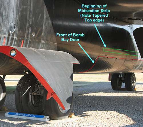
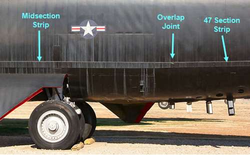
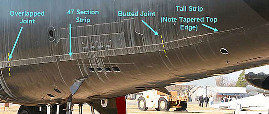
The longitudinal stiffeners were thick metal strips added to both sides of the fuselage to strengthen the frame and reduce the side-to-side motion of the tail during flight. These stiffeners are not rendered in the kit but they are a noticeable feature of the real B-52D.

Each stiffener begins at the front edge of the bomb bay and goes all the way back to just under the leading edge of the horizontal stabilizer, as shown in the three photos below. It looks like a single piece but was actually made up of three strips which I've named:  Midsection strip, 47-Section strip and Tail strip.


The stiffiners are made from 1 mm sheet styrene or equivalent stock. Cut 6 strips as follows:

   2 strips 2.5 mm wide x 198 mm long (Midsection Strips)

   2 strips 2.5 mm wide x 84 mm long (47-Section Strips)

   2 strips 2.5 mm wide x 33 mm long (Tail Strips)


Add the Left Side Tail Strip First

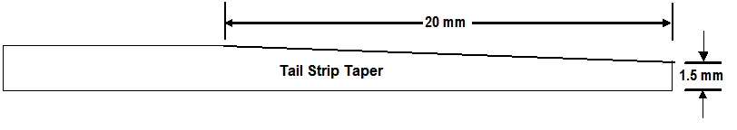
1.) Lay a Tail strip on a cutting surface, then taper the right end according to the  diagram below.


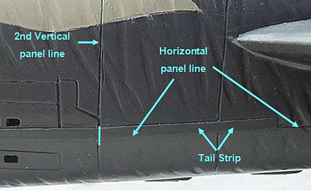
2.) Starting with the left fuselage half, locate the second vertical panel line in front of the horizontal stabilizer, as shown below. Follow this panel line down to the horizontal panel line that runs along the bottom half of the fuselage. This junction will mark the location of the left end of the Tail strip.

3.) Place the strip so that the bottom edge is aligned with the horizontal panel line and the bottom left corner is flush with the vertical panel line. The top edge will be slightly past the vertical panel line due to the change in direction of the horizontal panel line at this point.

4.) Trim the left end of the strip so it is parallel with the vertical panel line, as shown below.

5.) Glue the Tail strip to the fuselage.


 Next, Add the 47-Section Strip

1.) Lay a 47-Section strip along the horizontal panel line and trim the right end as necessary to butt up against the Tail strip.

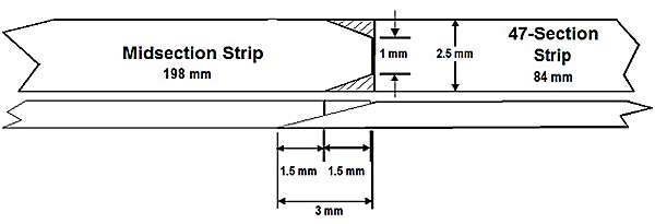
2.) Since the Midsection strip will overlap the left end of the 47-Section strip (overlap joint), you will need to taper the left end about 3mm, as shown in right half of the drawing below.

3.) Glue the 47-Section strip in place along the horizontal panel line.


Now Add the Midsection Strip

1.) Trim one end of the strip as shown in the left half of the drawing above. This will be the end that overlaps the 47-Section strip. Sand the overlapped ends so there is no buldge in the joint.

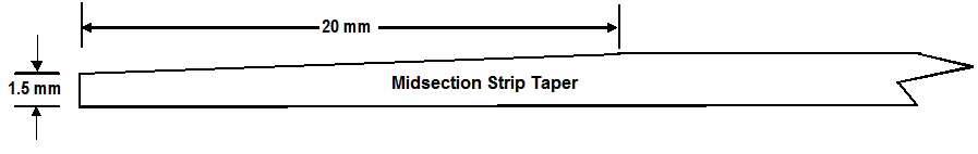
2.) Now taper the left end of the Midsection strip as shown in the drawing below.

3.) Align the bottom of the strip with the horizontal panel line and the right end with the 47-Section strip.

4.) Trim the left end as necessary to align it with the panel line at the front edge of the bomb bay door.

5.) Glue the strip in place.


  • Member since
    February 2010
  • From: Ontario, Canada
Posted by Bockscar on Friday, September 28, 2012 5:24 PM

Russ:

Really fab work man!

You have a knack for shapes.

I am a bit tied up for the next few weeks,

but I'll follow and chime in every now and again.

This is turning into an incredibly detailed and interesting build.

The bomb loading equipment is superb, I can almost

smell the flame-proof phosphate ester in the hydraulics.

-Dom

  • Member since
    April 2012
  • From: USA
Posted by Striker8241 on Saturday, September 29, 2012 9:00 AM

Thanks, Dom!  Hope to see you back soon, bud.

Russ


Inserted 7/4/19 from my notes.


Adding the ECM Chaff Ports to the 47-Section

Follow the procedure below to locate and create the chaff ports:

1.) Start with the left fuselage half. Locate the vertical panel line that runs even with the back edge of the rear wheel opening, as shown in the photo below.

2.) From this panel line, count 5 panel lines back towards the tail.

3.) Follow the fifth vertical panel line down to the horizontal panel line as shown above.

4.) Where the vertical panel line crosses the horizontal panel line, make a mark. This will be the center of the 8 chaff ports.

5. Using the measurements shown below, locate and outline the individual chaff ports.

6.) Carefully drill out and shape each port.


  • Member since
    April 2012
  • From: USA
Posted by Striker8241 on Saturday, September 29, 2012 4:59 PM

Ok, the lift trailer is essentially finished until I build another clip assembly and place it inside the trailer. I don't have any pictures of the inner part of the lift trailer so what I have is just a gesture. Thankfully, this will all be hidden with the clip inside.

Cheers,

Russ


Inserted 7/20/19.

The bomb lift trailer was called a Munitions Handling Unit (MHU). It was built in a "U" shape so that a bomb clip transporter could be backed into the open end. The lift arms inside the trailer engaged brackets attached to the bomb clip cradle and lifted the bomb clip while the transporter was removed. Then the bomb clip was lowered to a few inches above the pavement. All the wheels were swiveled 90 degrees and the MHU was pushed under the bomb bay. The bomb clip was then lifted up inside the bomb bay and attached to a frame at the top of the bay.

Tags: B-52D , bomb , lift , trailer , bay


  • Member since
    November 2010
  • From: Lafayette, Indiana
Posted by Son Of Medicine Man on Saturday, September 29, 2012 5:07 PM

That looks great Russ!  Excellent detail work!  Very realistic!  Yes  Yes 

Ken

  • Member since
    April 2012
  • From: USA
Posted by Striker8241 on Saturday, September 29, 2012 5:13 PM

Thanks, Ken!  Frankly, I'm glad to be done with it Big Smile


  • Member since
    April 2012
  • From: USA
Posted by Striker8241 on Sunday, September 30, 2012 9:22 AM

Hello, All,

I've been searching for a tail number of a Clinton-Sherman B-52D  that was on Okinawa in 1968 when I was there. Recently, I was fortunate to make contact with Sergeant Don Adams, who was the crew chief of 56-0612 which was at Okinawa at that time. If it was there, I worked on it Big Smile. With Don's concurrence, I will use his tail number on my model.

Many thanks, Don, and good job. Taking care of a plane that big was no easy task.

Russ


  • Member since
    November 2010
  • From: Lafayette, Indiana
Posted by Son Of Medicine Man on Sunday, September 30, 2012 11:09 AM

Great work on doing the research and making the connection Russ!

Ken

  • Member since
    April 2012
  • From: USA
Posted by Striker8241 on Sunday, September 30, 2012 1:11 PM

Thanks, Ken. I happened to leave a message on a Clinton-Sherman website and Don replied to it. Was a great good fortune Big Smile

Russ


  • Member since
    April 2012
  • From: USA
Posted by Striker8241 on Sunday, September 30, 2012 1:31 PM

Inserted 7/4/19 from First Annual Berny Memorial Group Build.


How to Make Wrinkles


I experimented with several tools but a triangular 3-corner jeweler's file turned out to be the ideal tool for the job. I used the sharp V-edged tip to gouge out the wrinkles. File the end flush so the edges are clean and sharp. NOTE: Using a small file this way can be really tough on your hand so I suggest using a file handle or wrap the tang with tape to improve your grip and protect your hand.

Practice on an old model or piece of plastic first until you get familiar with using the tool. Lightly gouge the wrinkles in a 2-3 inch area and observe their overall effect. You can always go back and make them deeper if necessary. Once you have a feel for the tool and its effect on the plastic, you'll be able to complete the cuts with one pass.

Once you're satisfied with the gouges, use a round file or a piece of folded sandpaper to round out the bottoms and sides of the wrinkles.

Wrinkle patterns were not uniform like a piece of corrugated roofing. They varied in shape and size and were sometimes broken up by vertical wrinkles or panel seams. I varied my cuts from 2-3 mm apart but I also varied the width of the troughs by using a round file or sandpaper.

Wrinkles in the nose area tend to slant toward the back while wrinkles in the midsection are mostly vertical. Wrinkles in the tail tend to be mostly vertical, but some are slanted toward the front.

NOTE: Avoid extending wrinkles into the following areas:

   * Ram air ducts and vent panels

   * Nose, chin and belly radomes

   * ECM chaff port panels and antenna panels (if you add them)

   * Gunner's hatch (if you outline it or cut it out)

   * Chute compartment door

   * Ammunition loading doors


Cheers and good luck!


  • Member since
    February 2010
  • From: Ontario, Canada
Posted by Bockscar on Sunday, September 30, 2012 3:25 PM

Thanks a lot Russ,

thanks for showing everyone what I

see in the mirror every morning.

-you're such a pal!.....lol

  • Member since
    April 2012
  • From: USA
Posted by Striker8241 on Sunday, September 30, 2012 3:37 PM

Lol! You too? Big Smile


  • Member since
    February 2010
  • From: Ontario, Canada
Posted by Bockscar on Tuesday, October 2, 2012 6:34 PM

Hey Russ:

This guy has fabulous shots of the Buff:

http://www.bubbamoose.com/b52.html

Here's one:

 Hmmm....wrinkles.....

  • Member since
    April 2012
  • From: USA
Posted by Striker8241 on Tuesday, October 2, 2012 7:01 PM

Fabulous! ... oh, you mean the plane...


  • Member since
    February 2010
  • From: Ontario, Canada
Posted by Bockscar on Tuesday, October 2, 2012 7:07 PM

Of course I mean't the plane,

errr.....wasn't talking about the wrinkles......

errrr.....yeah....errrr.....she's buff, or there 'bouts.......lol

  • Member since
    April 2012
  • From: USA
Posted by Striker8241 on Friday, October 5, 2012 8:30 PM

I've finally gotten to the point where I can button up this baby. I still need to install the landing gear and the tail gun turret. Still a lot of detail work to do on the outer fuselage once it's closed, including cleaning up the scribed panel lines, adding circular vents and adding the chin radar bulkheads and antenna. I plan to add the ECM antenna farm and other miscellaneous delicate protruberances later after I've installed the wings and stabilizers.

Cheers,

Russ


Inserted 6/30/19 from my notes.

Adding Some Detail to the Bomb Bay

Starting with the end bulkheads, I used a picture of one end of a real D-model bomb bay and printed two copies out on photo paper (see image below) then glued a copy to each bulkhead. If you want to use my image, use the Print Screen function on your computer to capture the image below. You may have to resize it to fit.


The photo below shows the image glued to one of the bulkheads.

That's all you need to do to the front bulkhead at this point. However, the rear bulkhead had a panel in front of it along the lower portion, as shown in the photo below.


Make this panel from 0.5mm styrene to the dimensions shown below.

Test fit the panel to be sure it will fit properly inside the curve of the fuselage as shown below, then paint the panel the same color as the bomb bay.


Set the panel aside for later use - it will be installed after the door thrusters are added.


  • Member since
    September 2009
  • From: Guam
Posted by sub revolution on Saturday, October 6, 2012 4:28 AM

Well, it doesn't have Red Stars, but I like how it looks and am getting excited to see more of it!

Hmm... I wonder if the Soviets ever captured a BUFF? Possible what if build....

NEW SIG

  • Member since
    April 2012
  • From: USA
Posted by Striker8241 on Saturday, October 6, 2012 3:51 PM

Hey, Sub, welcome back. Interesting thought but I don't believe that ever happened, although the North Vietnamese turned over parts of downed B-52s to them. I'm sure our crews had standing orders to bail out rather than try to make an emergency landing in enemy territory.

Russ


  • Member since
    April 2012
  • From: USA
Posted by Striker8241 on Sunday, October 7, 2012 5:12 PM

I came across some aerial refueling pictures that show I had the EWO hatch represented incorrectly as a scribed outline. In actuality, the EWO hatch had the same cover as the other hatches (see the first 2 pictures below).  I filled in the scribing and modelled the hatch and I will also add the guide marks above the cockpit ahead of the refueling probe, as shown in the third photo.


Cheers,

Russ


  • Member since
    April 2012
  • From: USA
Posted by Striker8241 on Thursday, October 11, 2012 10:28 AM

EWO hatch update - I discovered the EWO's hatch is actually the same type as the Bomb-Nav hatches; it was just really hard to see in the photos. The picture above shows the rounded support plate extending the full length of the hatch but it actually goes only half way. I will have to wait to correct this until I close the fuselage.


Tags: B-52D , fuselage , 1/72 , EWO


JOIN OUR COMMUNITY!

Our community is FREE to join. To participate you must either login or register for an account.

SEARCH FORUMS
FREE NEWSLETTER
By signing up you may also receive reader surveys and occasional special offers. We do not sell, rent or trade our email lists. View our Privacy Policy.