SEARCH FINESCALE.COM

Enter keywords or a search phrase below:

Trumpeter 1:32 F-105G Wild Weasel Build Thread

17156 views
91 replies
1 rating 2 rating 3 rating 4 rating 5 rating
  • Member since
    March 2012
  • From: Louisville, KY
Trumpeter 1:32 F-105G Wild Weasel Build Thread
Posted by Builder 2010 on Wednesday, January 2, 2019 6:48 PM

Happy New Year!

I'm not starting this build right now so don't get too excited, but I have the kit in my possession. I have to first finish the Bronx Victorian which I've invested $$$ heavily.

The Wild Weasel is a commision build for the same person for whom I build that nice "Yankee Lady" Monogram 1:48 B-17G a couple of years ago. He was able to buy this new model for a very low price since Allied Hobbies in Philadelphia is going out of business and was selling things for 70% off. This time I'm getting paid! We're bartering... He's going to give me a Tamiya 1:32 De Havalind Mosquito kit. I've really wanted to build that plane!

The kit shows $124. He got it for $50. Good deal. It's an older Trumpeter kit and I'm expecting the usual old Trumpeter problems. This will be my 3rd Trumpeter large scale plane so I'm getting used to them. It has those finicky PE flight surfaces hinges. On the TBM I just glued the flaps and ailerons, but did get a movable rudder and elevators. On this one, I'll try that again. 

I've ordered some aftermarket for the F-105G including two resin ejection seats with pilots, Eduard cockpit details, and G-Force brass landing struts. The model is big and heavy and I've read that the plastic gear isn't sturdy enough. It has a complete J-75 turbo-jet included which will be completely hidden so I'm either going to cut some access hatches to show it off or make a service rack and mount it outside the plane. I will attempt to super-detail the engine and the other usual places. The plane has a fully detailed Gatling gun and I will show that off too.

So sit tight. I will be back at this thread in a month or so when the Bronx Building is complete.

And after it, I will also regale you with the construction of the Mossie.

  • Member since
    July 2004
  • From: Sonora Desert
Posted by stikpusher on Wednesday, January 2, 2019 9:40 PM

Well, you can never go wrong with a Thud Weasel, no matter what the shortcomings are...


F is for FIRE, That burns down the whole town!

U is for URANIUM... BOMBS!

N is for NO SURVIVORS...

       - Plankton

LSM


  • Member since
    September 2012
Posted by GMorrison on Wednesday, January 2, 2019 9:56 PM

I'm in with the clam dip!

SEA, big scale, big mean airplane.

I have never seen one of these fly although I have seen quite a few at shows.

It's probably Republic's last big program- the A-10 was both Republic and Fairchild.

 Modeling is an excuse to buy books.


  • Member since
    March 2010
  • From: MN
Posted by Nathan T on Wednesday, January 2, 2019 11:00 PM

Saaaweeet! I built Trumpy’s younger brother in 1 48 scale, and you’ll definitely need those metal landing gear. It’s more so the attachment part of the gear legs that’s the weak point. The bottom wing is so thin that the attachment hole isn’t very deep. 

What are you doing for ordinance?


  • Member since
    September 2012
Posted by GMorrison on Wednesday, January 2, 2019 11:59 PM

"First in, last out" has a lot of detail on that.

Two ARMs.

 Modeling is an excuse to buy books.


  • Member since
    May 2016
Posted by Hobbie on Thursday, January 3, 2019 3:18 AM

Big bird! I'm taking a seat, this should be interesting! :-) 

His older 1/48 Revellogram brothers already look big and mean!

Did Trumpeteer's infamous Mad Riveter went to town on this one also? The 1/72 version had parts looking like a cheese grater...

Arguing with an engineer is like wrestling with a pig in the mud : after a while, you realize the pig likes it.

  • Member since
    March 2012
  • From: Louisville, KY
Posted by Builder 2010 on Thursday, January 3, 2019 1:04 PM

Riveting looks modest. I don't yet know what ordinance, but since it's a anti-radiation plane, the HARM missiles seem like a must-have. I suppose you need to do this pretty early on if you need to drill out mounting holes. I'll have to study the instructions to see what those are. I also need to get a reference book on this bird, and FSM just reviewed a F-105 A-F book by MMP, but it's $40, and that's a little steep. I'll see if there's other stuff available. There's always Google.

  • Member since
    January 2015
Posted by TheMongoose on Thursday, January 3, 2019 9:08 PM

If you've got a 1/2 price book seller near you check them out. It's a long shot but the one near us gets this stuff in every once in awhile. You may get lucky!

In the pattern: Scale Shipyard's 1/48 Balao Class Sub! leaning out the list...NOT! Ha, added to it again - Viper MkVii, 1/32 THUD & F-15J plus a weekend madness build!

  • Member since
    July 2004
  • From: Sonora Desert
Posted by stikpusher on Thursday, January 3, 2019 11:10 PM

Squadron has a good book with tons of photos for reference, “Wild Weasel- The SAM Suppresion Story”, that covers the whole SEAD program. At least until the 90s and before the Balkan Wars, when the F-16 took over the SEAD role. From early efforts in Korea, thru the whole Vietnam Air war effort, to finally Desert Storm. It is quite affordable, and a great starting point. 

As a side note, Shrike ARMs will be your primary weapon for a Thud Weasel in Vietnam. The Standard ARM did not appear until late in the war. Early Thud Weasels often carried CBUs in a”flat four” configuration on the centerline rack as well.


F is for FIRE, That burns down the whole town!

U is for URANIUM... BOMBS!

N is for NO SURVIVORS...

       - Plankton

LSM


Ole
  • Member since
    October 2018
  • From: Central VA
Posted by Ole on Friday, January 4, 2019 5:40 AM

I've built this kit years ago and it's really nice without any major issues. Good thing you already got the metal landing gear. That is a must for this kit. It's too heavy for the plastic gear.

  • Member since
    March 2012
  • From: Louisville, KY
Posted by Builder 2010 on Friday, January 11, 2019 5:25 PM

I bought 2 Aires Ejection Seats with pilots, resin rear-flank air inlets, and Eduard's cockpit instruments/placards, but the G-Force gear was out of stock at my LHS' suppliers. So the fellow for whom I'm building the model located them on ebay and they were delivered to my home today. I suspect I may have to solder the gear to a brass plate and glue that into the airframe, especially since the mounting is depending on those thin wing skins.

I still have a few weeks of work on the Bronx Building that I'm constructing for the railroad and it's coming out quite well. I had some of the more intricate architectural details 3D printed, and am constructing the remaining cornices. All the rest is laser cut.


It's going to be one heck of a building.

So stay tuned.

  • Member since
    March 2012
  • From: Louisville, KY
Posted by Builder 2010 on Thursday, March 7, 2019 7:47 PM

Well sports fans, work has finally commenced on the Trumpeter F-105G Wild Weasel. I am just about finishing up on the Victorian town house that's a few days away from being installed on my model railroad. It came out really well and represents another potential model railroad magazine article.

Building is lit by surface mount LEDs and the interior is an art gallery (which is the use of the actual building in the Bronx). Here it's mounted on it base ready to go on the railroad.

What I'm currently doing is adding some resin cast roof parapet caps. I made the master out of Super Sculpey and cast them, one at a time, in a silicone mold. When I finish the last three tomorrow, I will paint them a terra cotta color and glue them to the roof edge.

BACK TO THE WILD WEASEL:

I unboxed the whole deal today and again used my home made, albeit too narrow, sprue organizer. 

Not shown are four large sprues containing lots and lots of ordinance, most of which will not be used.

The first thing I did today was attack one of two Aires resin ejection seats with pilot. There is a huge block of resin that you optionally can remove to free up the seat's legs that sit on the flight deck. I chose to do this to see if I could.

Using razor saws, then carbide router and finally a diamond coated burr, I was able to hollow other the bottom without accidentally removing the legs (which is quite easy to do with a Dremel and Flexi-shaft.) I did put an errant divot in one rear leg, but I have the best solution ever for this kind of repair: Bondic UV curing clear resin. You fill the hole, shine the attached UV LED light on it and in about 5 to 10 seconds it's solid as a ceramic. Dentists have been using this stuff for some time now.

Here's the first seat sitting in the cockpit tub just for fun.

It's going to be fun painting all the details in these seats.

I'm also going to add the Eduard Interior set. It's quite huge and comprehensive. 

So stick around folks. Over the next couple of weeks construction will move ahead apace. It's going to be a very big (long) airplane.

  • Member since
    November 2008
  • From: Far Northern CA
Posted by mrmike on Thursday, March 7, 2019 9:57 PM

Stickin' right here - your builds are always entertaining and informative, and your skills are an inspiration!

  • Member since
    March 2012
  • From: Louisville, KY
Posted by Builder 2010 on Friday, March 8, 2019 5:33 PM

I continued working today cleaning up the resin casting of the ejection seat. I cut the legs free on the 2nd seat, and did slip with the carbide router and clipped off half of one of the front feet. Luckily, I had a "dental" solution. I drilled the leg stump with a 0.022" drill and inserted some phosphor bronze rod of the same diameter held with some CA. I then built up layers of Bondic UV curing filler. Between each layer I illuminated it with the UV LED light. It cures in 5 to 10 seconds and is ceramic hard. With the rod reinforcing the piece the new leg is stronger than the existing one. This will not be visible in the finished cockpit, but the new leg does have to support the seat at the right height and angle. This is almost exactly the same technique that dentists use to restore a broken tooth with a pin and composite light-cured material.

In addition to replacing the missing leg, there was also a large entrained bubble in the seat bottom that penetrated through the seat side and also got filled with the Bondic. If you havn't done so, get some Bondic. It's not the ultimate adhesive, but it does some things that other materials just can't. Unlike CA, it doesn't cure until you shine the light on it. You can wipe it off and not screw anything up. It's great for adhering transparent parts where the UV can hit it. No UV, no cure.

The last thing I did was clean up the arms and heads, and then insert some more phosphor bronze rods to act as holders for these parts. After trial fitting the arms and heads I realized that they would block access to body parts lying underneath making painting more difficult. So I'm going to paint these pieces separately and then join them. I'll liquid mask the spots where the arms and head will go to make gluing more secure.

I added the plastic control boards to the four armrests in the cockpit tub. These pieces need to be there and then you're supposed to remove all of the relief detail in prep for the Eduard PE replacements. I have a quandry. I'm not sure what color to paint the interior. It calls for "Interior Gray". I have no idea what that is. The light gray of the kit could very well be the "interior gray". Or could Tamiya Gray Primer be the color. Who can help me here? If I paint them, I'm going to mask the surfaces where the PE goes again to insure a good glue bond.

  • Member since
    February 2013
Posted by tomwatkins45 on Friday, March 8, 2019 5:50 PM

The interior, including the seats should be dark gull gray FS36231. I'm looking forward to seeing this big beast come together.

Hope this helps,

Tom

  • Member since
    January 2010
Posted by CrashTestDummy on Monday, March 11, 2019 1:31 PM
Watching. My uncle was a test pilot for Republic, and worked on the F-105 project.

G. Beaird,

Pearland, Texas

  • Member since
    March 2012
  • From: Louisville, KY
Posted by Builder 2010 on Monday, March 11, 2019 6:06 PM

I might have that color... I bought some Tamiya Japanese Light Gray that might work also. I may have the light gull gray. I started working on the PE officially today and coordinating the work with the Eduard instructions. It's a challenge (to me at least) switching back and forth between what and when Eduard wants, and the kit's instructions. I like to prime the PE using a good primer to help the top coats adhere. Before priming I went over all the non-pre-printed PE with a scratch brush to rough up the surface on both sides to provide tooth for the primer and the CA that's going to hold the PE to styrene. 

The Eduard instructions call for the entire cockpit tub to be installed 4mm higher in the fuselage. To accomplish this they have you remove the 4mm from the bulkhead that lies behind the pilots position, and provides PE folded shims that raise the tub up higher into the fuselage. Very clever... I hope it works. It will make the cockpit details more visible.

Also included in the Eduard set are fully detailed side panels. They are folded affairs with a very tight double fold that has about 1/32" between one bend and the other making a full 180 degree turn. I primed one side of the PE, and then after folding, primed the now bare-brass backside (don't say that last phrase too quicklyConfused too.

This image shows the primed PE, the cut-down bulkhead, and the folded side panels for the starboard side of the aircraft. The model did not have any side panel details.

I'm still not sure if I want to scrap off all the arm rest details and use the printed Eduard PE parts. While the Eduard printing is highly detailed, it has very little relief. Besides, I really enjoy picking out cockpit details. I have some amazingly pointy brushes perfectly equipped to do this. I may mix and match, using the Eduard in some cases, but the model's in others. There are a whole raft of little PE boxes and details that go onto those side panels. And I am going to use those.

I also primed all the ejection seats/Pilots pieces to get ready to paint them. That too will be fun.

Somebody on one of the many forums on which I contribute gave a great suggestion: Eyeliner makeup brushes. They have the finest points of any brush I own and are available from Amazon. They're resistant to all of our modeling solvents including acetone, iso alcohol, mineral spirits and Tamiya glues. But wait, there's more... they cost $7.99 for 100. Yes! You read that correctly! They're 8 cents apiece. When they get munged up, you throw them out. This is just one bag. You get two of these!

If you're interested, here's the link: https://i.postimg.cc/VsqJcjYd/Make-Up-Brushes.jpg

Just thought I'd share this since I'm going to use them to detail the cockpit switches.

  • Member since
    March 2012
  • From: Louisville, KY
Posted by Builder 2010 on Thursday, March 14, 2019 5:53 PM

I started today's session by finally deciding that I was going to leave the kit's unpainted light gray to be the base color for the cockpit. I also decided to use the kit's side panel switches instead of scaping them off for the Eduard PE. But I did decide to scrape off the knobs on the angled panels since I like the Eduard's better. I really enjoy painting knobs and buttons... I masked the tub to just expose the side panels and airbrushed them semi-gloss black.

After pulling all that tape I was pleased with the result.

I found some great pictures of the Thud's ejection seat and used it plus the instructions that came with the resin seat/pilot to color it. The instructions didn't include any information about the seat itself. It's not the light interior gray like the cockpit wall are. Instead it's clearly a medium gray. 

The resin seat is very complete, but still has a couple of things missing including that yellow (ejection handle?) on the seat's left side. I airbrushed the gray first.

The resin seat was also missing the red head pad, but the kit's pad was not configured right to just glue on, so I used the fine razor saw to separate the pad from the rest of the molding and then CA'd it to the seat frame.

After gluing I painted it red using Vallejo paint. Although the instruction called out "Olive" and "Olive Green" as the two colors for the flight suit and the Mach suit, I don't have colors by those names. But the ones I do have (Olive Drab and Khaki) look very much like the colors actually printed in the resin seat's instructions, so I used them.

I used a combination of brushes to paint all these details. The seat picture (above) showed the seat cushions to be darker than the frame and the seat belts to be a much lighter gray, so I attempted to match them as well.

There's some wet paint in the above picture which is where the highlights are coming from. I started using Tamiya Retarder for the first time. It improves flow and slows down drying which helps in brush painting the Tamiya colors. The oxygen hose and mask is Tamiya Nato Black. Shoes are semi-gloss black.

I also painted the arms which are hung in a cool painting fixture that I won as a door prize at a Military Modelers Club of Louisville. It was designed and 3D printed at the Advanced Manufuring Processes Lab at University of Louisville Speed School of Engineering. One of our new club members is a technical manager at this facility. It swivels on an enclosed ball bearing.

The arms are Olive Drab with Khaki gloves. The last pieces to paint are the all-important heads. The eye openings are very narrow and I suspect, it will be close to impossible to render the eyes in any meaningful way. You can see those metal extension paying off in holding these small parts.

Here are the two seats sitting in the tub for a status shot. 

I really like cockpits! To me, they're the most interesting aspect of aircraft modeling. Next is engines and followed by landing gear. It's way I find modeling drones and UCAVs very dissatisfying. No cockpit!

I'm a pretty basic figure painter. I don't really do shading and shadowing, although I probably will on the facials features. I'm careful, just not that artistic. Once the pilots are done, I really dig into putting the cockpit together with tons of PE.

  • Member since
    April 2012
  • From: USA
Posted by Striker8241 on Friday, March 15, 2019 7:58 PM

This is really an interesting build of a fascinating airplane  - I worked on the Weasels and most other 105 models in Thailand in 69. Will be watching this beauty come together. 

Cheers,

Russ


  • Member since
    March 2012
  • From: Louisville, KY
Posted by Builder 2010 on Friday, March 15, 2019 8:12 PM

I hope you don't remember too much about them since I'm probably going to take some "modeler's license" in the build.

I painted those heads today. All that's left is the white of the helmet. I use a mixture of Vallejo Shadow Flesh and white to create a decent flesh tone. I was able... barely... to paint the eyes along with the iris. I then used the Molotow Chrome Pen to put a coating of bright silver on the visors and then go back and coat with Tamiya Clear Green. Tomorrow I'll get the white on and put the heads together with the bodies.

I then got back to work on the cockpit proper. I painted the knobs and switches on the kit side sill parts and then added the starboard side Eduard 2-layer diagonal panels. I added all the extra PE on the folded PE startboard side panels and got the forward one installed. The aft panel was ready to install when dinner time came.

There's a couple of added pieces in the above picture that still need some paint besides the gray primer. I like how the side panels are going to really spiff up the cockpit, and am also concerned that little or none of this will be visible when the cockpit's closed up. I certainly hope it will be seen. This is slow, painstaking work, but it's fun.

I use gel or thick CA to hold PE to a model. I didn't used to, but Brian Bunger, proprietor of Scale Reproductions, Inc, our excellent local hobby shop, said that he uses gel since it stays put and you can apply tiny amounts in a very controlled manner. And it doesn't set instantly so you actually have the chance to move the part a bit if it's not perfect when you lay it down.

I have another question. What's a good way to add that yellow or white seal that's between the canopy glazing and the canopy frame? I've been thinking of different ways to do that, but haven't come to conclusion about how to actually do it without making a mess.

  • Member since
    January 2015
Posted by TheMongoose on Sunday, March 17, 2019 7:40 AM

For the seal around the canopy glass here’s what I did- cut Tamiya tape and placed it around the canopy leaving it just shy of the edges, sprayed on a custom mix of dark flesh and white cause I couldn’t buy radome tan at lhs (they were out of all things), clear coated, taped over whole cockpit like normal. When you pull the tape off at the end if a little of the seal comes up it ends up making it look more realistic imo. 

Let us know how you do it. You’ll definitely add another level of realism to the AC. Your builds are always fun to watch.

In the pattern: Scale Shipyard's 1/48 Balao Class Sub! leaning out the list...NOT! Ha, added to it again - Viper MkVii, 1/32 THUD & F-15J plus a weekend madness build!

  • Member since
    March 2012
  • From: Louisville, KY
Posted by Builder 2010 on Monday, March 18, 2019 8:15 PM

That's probably how I'll tackle it. I did find that Montex Masks has a complete set for the F-105G Wild Weasel including two layers to do the gasketing, but it's only available from the U.K. (everyone else is out of stock) and even though the masks are only about $6, the shipping was almost $30. That's too much money for some gasketing. I'll do it by hand and it will work out.

I painted the pilot's helmets on Sunday and glued their heads in place. The heads are exactly the same so I had them facing in different directions so it was harder to tell they were twins. In the picture you can also see the left front side panel in place for the picture. It's not glued in. One of the Eduard add-ons was some kind of map case that side on the right side control panel in the rear cockpit, but it's sticking out too far. It's causing the ejection seat to be forced to far to the left. I'm going to remove it. The arms will go on when I can verify their positioning.

I started working on the front instrument panel. As usual, I had my normal wrestling match with Eduard PE. A couple of parts disappeared into the ether, and another, after preparing it, just wouldn't really work. But all in all, the panel is impressive.

The plans call for a plastic rod 5.5mm in diameter and 10mm long to simulate the radar scope housing. I took a piece of excess Plastruct ABS 1/4" tubing and machined it down to 5.5mm, but it was way too small. The opening actually measured 5.82mm, so I machined the rod further down and got the size correct. Then you have to file a flat to correspond to the flat in the opening. 

I glued it in and painted the housing semi-gloss black.

The tubing had a hole in it (hey... it was tubing), so I cut a styrene circle to close it off.

Onto this goes a PE pre-painted ring. Before I put it on, I first chromed the screen with the Molotow and then coated it with Tamiya Transparent Green to make it more "exotic". I then glued on the PE ring.

It created the desired effect. I also coated all the gauge faces with multiple coats of Testors Wet Look Clear to simulate glass faces.

There was another piece of IMPOSSIBLE PE that was supposed to go on this. It was the sun shield. I was very narrow, although tapered to wider at the top. You were supposed to somehow connect a tiny tab on the one end to the widest part at the other. I chose to attempt to solder it. I did solder it, but it was not round, looked like crap, and I decided it was better off, then on looking like that. The one for the back radar disappeared into the ether so neither radar will have one. I may make one out of some scrap PE fret.

This is what it looked like. Sometimes "not used PE" is better than "really terrible PE".

There's some other nearly impossible PE that goes on the front panel in the form of T-handled levers, and one other lever. They're supposed to be glued end-on onto tiny points on the panel and I am dubious about how well this would work. I would be much happier if they were able to be inserted into holes. But drilling holes in some of these areas will be very, very difficult. We'll see...

  • Member since
    March 2012
  • From: Louisville, KY
Posted by Builder 2010 on Wednesday, March 20, 2019 9:05 PM

Got the left side cockpit walls in place today.

And I got two of the four rudder pedals in place. These are PE folded and glued assemblies. I momentarily thought about soldering them together, put quickly dispelled that idea since there's no stress on these pieces which wlll be out of sight under the pilot's feet. The pieces are not finished painted or showing any wear yet. I'll do that on Friday. Tomorrow we're heading to Cincy to go to the art museum. The left one's a bit cockeyed, but please refer to my last sentence regarding the time I should spend trying to rip it off and glue it on straighter.

  • Member since
    March 2012
  • From: Louisville, KY
Posted by Builder 2010 on Friday, March 22, 2019 6:08 PM

Short session today, interrupted by a delivery for the trains. That said, I did get a lot done on the rear seat instrument panel. Again, like I did in the front, I put a spacer between the panel base to stiffen it up a bit.

The front panel is very interesting with some added PE parts that were inserted in small tab slots. I still have more to add and will do it on Monday.

On Monday also, all the cockpit parts will be installed including the pilots and their arms and then it will be onto the rest of the airframe. Have a great weekend. Spring appears to be arriving in Louisville. Trees are blossoming and allergies are terrible.

  • Member since
    August 2015
  • From: the redlands Fl
Posted by crown r n7 on Friday, March 22, 2019 6:40 PM

That’s looking real good there 


 Nick.

  • Member since
    March 2012
  • From: Louisville, KY
Posted by Builder 2010 on Tuesday, March 26, 2019 9:08 PM

Somehow, yesterday's post didn't take so I'll do it again, and then post today's work.

Well... thank you! But you may have to eat those words after you read today's post.


Today was kind of bittersweet. It started well and then ended weird.


The start was finishing the rear panel, installing both and then getting the pilots all fitted. The rear panel looks terrific. There are layers of PE that adds to its dimensionality, even though it just flat PE. It went into the plane without too much difficult, although it meant removing the replacing the front position's rudder pedals. I really like the raised sun shields that were separate pieces of PE with actual locking tabs to secure them to the panel.


533098


I had to file the inner sides of the pilots' shoes to have them pass by the front and back panel's center console. I also had to clean up the resin casting a bit around the shoulder joint so the arms would glue on flush. The left hand sort of reaches the side panel. The right arm should grasp the stick, so I put the sticks in, and before they dried hard, I put on the arm and moved the stick head and the arm into junction.


533099


The pilots need some touch up painting due to the handling and arm joining exercise.


That was the good part of the session. I removed all the sprue nubs on the long fuze sides, but didn't doing any filing. I'll do that when the halves are joined and filled. The next kit steps included building the 20mm Vulcan Cannon. I was looking forward to this build, but got more disappointed the further in I got. So problems are Trumpeter's engineering and some are my idiocy.


The barrels are separate pieces and are frail. I got it together, and it was annoying to get the barrel ends into the end piece. There were small divots for each barrel end to lay, but they weren't deep. I'd get one end and two would pop out. This end should have slid over the barrels ends like the center spacer. If it was a Tamiya kit it would have gone togehter perfectly.


533100


I put this aside to dry. I then went on to put the rest of the gun parts on. Now... I usually don't clip all of the parts of a particular step off the sprues, but I've watched a lot of videos build videos and a lot of the guys clip all the parts of a particular step and have a pile of parts waiting to be assembled.


So I did this for the gun. And now I also know why I usually don't build models this way. There is a 2-part curved mounting bracket that wraps around the breach portion of the gun. I found one part on the work bench, but the other was... where? Not on the bench any more. So I did the floor sweep and search and found the part broken in half with half missing. My desk chair wheel caught when I wheeled back to try and find it. That's not the first time that's happened and when it does, it's usually bad. Murphey's law at work.


So I had to scratch-build one half of the part. I carefully measured all the critica measurements and fabbed the missing part out of 0.040" square styrene stock. 533101


I used 0.040" round styrene rod for the spacers with 0.021" phosphor bronze wire to hold it all together. Then disaster struck again. I was using the hot air gun to force dry some touchup paint on the flight control sticks and the darn thing blew the other good part... somewhere... Couldn't find it! So I had to scratch-build the entire piece which greatly complicated it.


The rest of the gun seemed like it dried enough to handle and I went about trying to drill out the muzzle ends on that end cap piece that had little stubs sticking out representing the barrel ends. In my handling of the gun, the barrels separated from the end cap. Now they were harder to get in place since there was another ring surrounding them and it made positioning them much harder.


I added some CA into the end cap and hoped to get the guns into their respective divots, but what I didn't realize until it was too late, that I was torquing the whole deal and three of the barrels had broken in half in their middles.


So now I have to scratch-build them too. They measure a nominal 1.0mm and I have some great Albion Brass Tubing of that diameter. I tried to separate the muzzle ring from the backing ring, but of course the CA really held that So I can't use that piece either. The last thing I did was machine a new muzzle ring (.218"), scribe the barrel spacing, and start to lay out the six barrel holes.


533102


Here's the end view of the muzzle end showing the beginning of the hole spacing. Using the 3-jaws of the lathe chuck as a spacing guage, I located three of the six holes. The other three will go between these.


533103


If none of this works, I can always just close up the gun access hatches and just have the muzzle end behind the cannon opening. I think it wil work. I have to drill the other end of the barrels to tie the 1mm brass into the rest of the gun.


I'm not going to pre-cut stuff before building. Too easy to lose parts!

  • Member since
    March 2012
  • From: Louisville, KY
Posted by Builder 2010 on Tuesday, March 26, 2019 9:28 PM

Now to today's disaster...

After I decided to make brass barrels and a new end piece, I realized that I could still use the kit's front piece by just drilling out the muzzle ends nubs and inserting the brass barrels through like the real guns do. 

I drilled the other end where the barrels widen to accept a piece of .8mm Albion tubing which the 1mm tubing will slip over. I did this becuse there wasn't enough beef in barrels behind that piece to let me drill the 1mm holes without the barrels disintegrating.

I also realized that the plastic barrels being so wrecked I really didn't know the actual barrel length I needed to cut out of the 1mm brass tubing. So I temporarily installed the main part of the gun and the forward support in their respective locations and then measure what the barrel length should be.

I drilled out the front piece, but because of the support around it, I was hard to see inside when I had to insert all 6 barrels through the holes.

To cut the barrels equal length I put down some 3M double-sided tape, then marked off the length with some Tamiya tape and cut the barrels by rolling a sharp #11 blade until the thin tubing breaks.

I slide the 1mm tubes over the .8mm tubes and held with a tad of thin CA. Then I attempted to wrestly all those barrels into all those holes while keeping the front piece in the proper location since it had an alignment lug on the rear side that engaged in a slot in the plane's gun chamber.

After fussing with it try to hold everything still with my left hand while trying to position the tubes I realized quickly that it wasn't going to work. So I put some 0.021" phosphor bronze wires of varying lengths into the barrels to act as guides to get the barrels into their respective holes. Then I put the main part of the gun into my PanaVise.

I fussed and fussed, and wasn't getting anywhere. I found that even though the guide wires were different lengths, they weren't positioned properly. I rearranged them so the two longest on opposite sides, the next longest on the right side of these and the shortest on the left. That way I could manage how and to what holes they were going into.

Then the $^&(*^% hit the fan!!!

The piece will all the barrels sticking up and four out of the six alignment pins in the correct holes LITERALLY EXPLODED OUT OF THE VISE!!! Some of the guide wires ended up on the bench, but the gun and all those barrels had disappeared into thin air, or so it would seem. After looking everywhere, I find it down inside the zipper hoodie sweatshirt I like to ware in the basement.

I retrieved everything except that critical front piece with the hole plate and the mounting bracket. I'll look for it tomorrw. If not, I'll drill out that aluminum piece and cobble together something to support it in the gun compartment. 

This gun is turning into a real pain in the Butt!

  • Member since
    January 2015
Posted by TheMongoose on Wednesday, March 27, 2019 11:15 AM

Oh man i totally feel your pain. You chose the right path tho, just walk away, relax, and with luck you'll find it first thing tomorrow!. Unlike me who would probably step on it to find it lol

In the pattern: Scale Shipyard's 1/48 Balao Class Sub! leaning out the list...NOT! Ha, added to it again - Viper MkVii, 1/32 THUD & F-15J plus a weekend madness build!

  • Member since
    March 2012
  • From: Louisville, KY
Posted by Builder 2010 on Wednesday, March 27, 2019 6:09 PM

Oh... you are so correct! I did sleep on it. First of all I was completely ready to use the metal front spacer since the other one was gone—or so it would seem. I thought about how to hold it in a vise without undue stress and without it exploding out again. I came upon using Sculpey clay to form around the odd shape and then fire it to make a fixture. But then I realized that it probably would work in its soft form since it just had to stabilize the gun.

I actually made another front bracket and spent a lot of time getting its contours perfect. To do this without the original, I traced the profile at the open end of the gun trough in the left fuselage half. The contour opened up slightly as it went forward, so I had to make a second one with the bottom curve opened up a bit. I was all ready to glue that into the fuselage, and decided to make another front piece as I mentioned. When I got back to the work bench that part had disappeared. I don't know what happened to it. I had been holding it or carrying around and putting it down somewhere. It was just gone.

Now I have writen ad infinitum about the dimensional rift that absorbs parts and then spits them out again. It's a quantum mechanical thing... So I machined another front spacer just to have two (one to practice on), and I had swept the floor twice and laid down to with my eyes at floor level to see anything that was sticking up. Nothing. Then a little time later, I moved the bench forward on its wheel just a bit and there was the plastic front piece just sitting right in the middle of the floor. Seriously. It wasn't there a few minutes before. So I was able to get back to assembling the gun as I originally planned.

The wire idea worked just as I thought would once I had the gun stable enough that I could tip the vise forward so I could visualize the holes. Having different lengths of guide wires helped so I didn't have to get two wires into the holes at the same time. A couple of the wires insisted on going into the wrong holes, but patience paid off and all six went into their correct spots. Here are all 6 wires through the holes with the barrels waiting to follow.
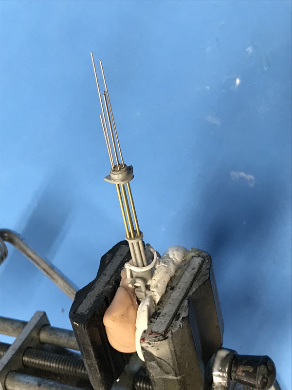
The 1mm barrel fit in the holes was perfect and it didn't take much persuasion to get the barrels to follow the guide wires. In fact, this part went much easier than I thought. Heck, I deserved a break!
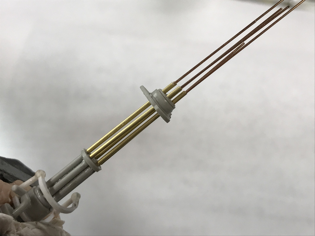
All that was left to do was slide out the guide wires and carefully file the barrel ends so they were all perfectly equal. I debuured the bores and then took this picture.
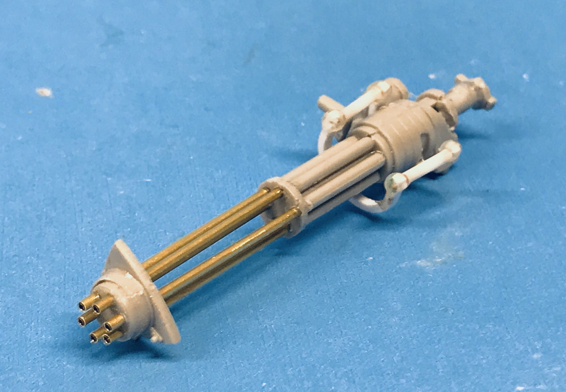
I tried my hybrid into the gun chamber and found the barrel length I chose to be okay, so I then sent it to the paint shop.
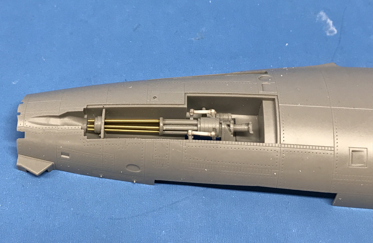
I sprayed the gun with Tamiya Gray primer since I wanted to be sure that the metal parts would hold paint better.
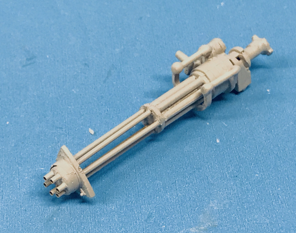
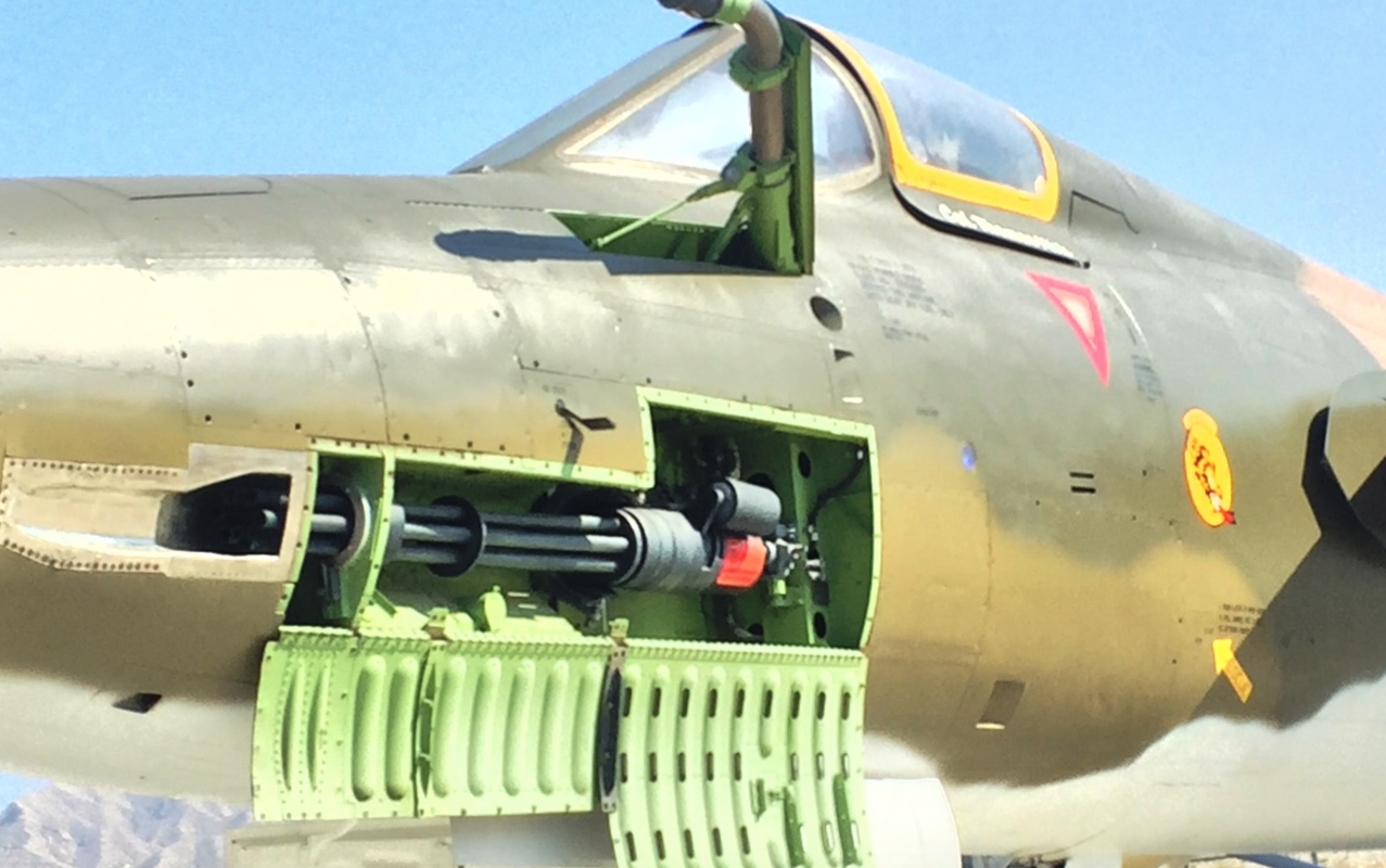
The instructions call for "gun metal", but when you look at these weapons, they're basically black. I'm going to paint it semi-gloss black. But when you look at this picture, the gun is actually pretty gray. I figure something out. The Eduard set includes new wall for the gun compartment. It did not have a new PE door. That was in a different set which I did not get. I notice there's and another spacer on those barrels which was not in the kit and would have made getting the barrels on the front spacer easier.
I glued together the cylindrical magazine, cleaned up the joints and then set it asside. It gets painted aluminum and has the 20mm ammo belts attached to it, but it really won't be visible.

I started building the J75 Turbojet Engine. This was a 2nd Generation jet engine and was not a turbofan like many 3rd Gen engines are. I vacilated about stripping off all the molded piping, but then said, "What the heck", I like jet engines and I'm going to make this one with a separate stand so it can be displayed outside of the plane.

Here's a picture of the J75. I need to find an opposite side view since to do an adequate piping job is going to require 360 degrees of detailing. If anyone has a source, please let me know.
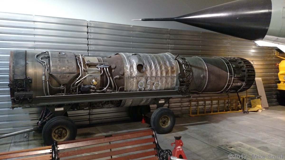
All of the 3D boxes and covers are pretty much included in the kit, so the real challenge will all the piping in between.

Before I started removing the piping I took some pictures so I could at least put the ones back that I removed. I have .5mm solder wire that works for the smaller diameter tubing. I have enought various plastic and brass wire shapes to do all the piping.
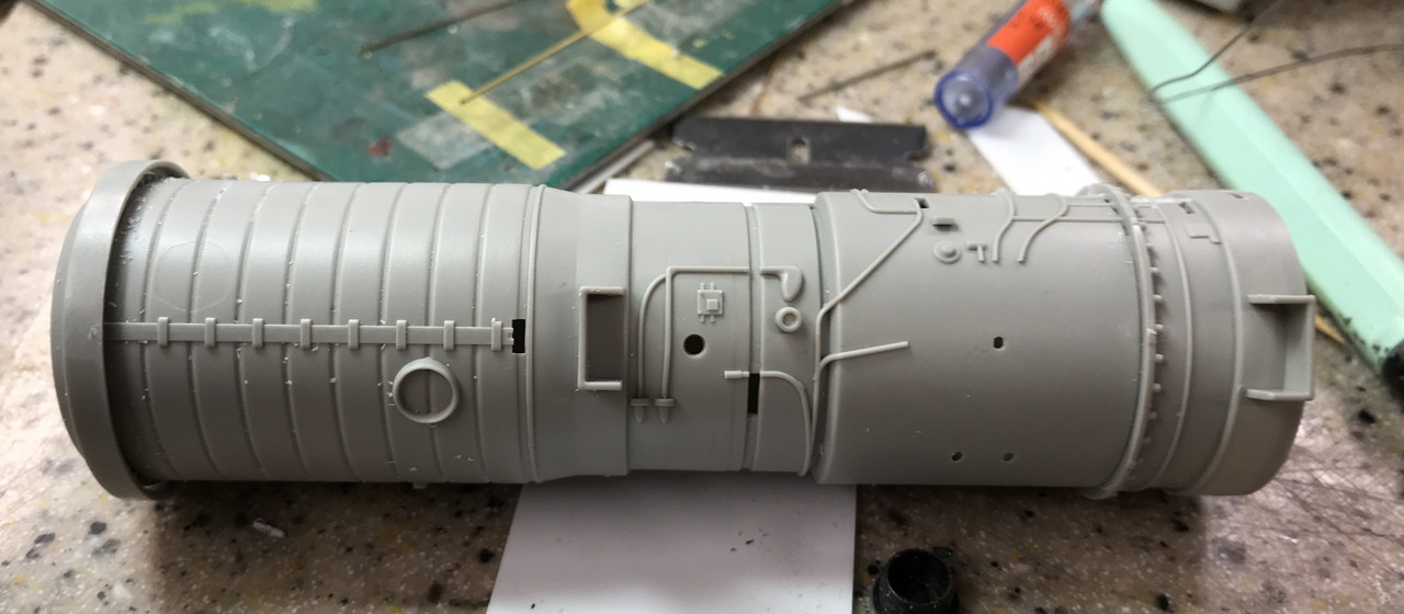
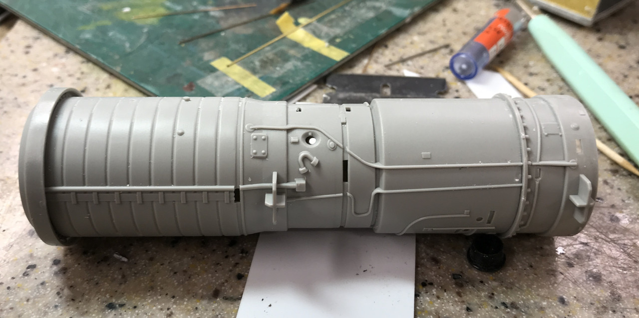
I used the MicroMark chiself to remove the relief piping.

I then started gluing on the valve and control bodies. I almost has a screw up. The front compressor guide vane should have gone on BEFORE the engine halves were glued together, but I was able to pop it apart enough to get the vane in place. I then filled the resulting gap with some thick CA and sanded smooth.
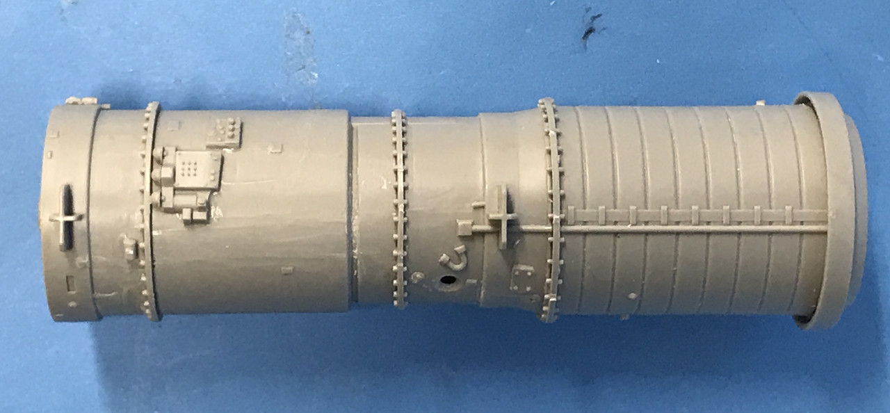
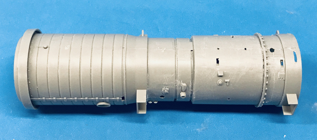
I also started drilling the various remaining nipples and junctions to receive the piping. Since most of the piping is bright stainless steel, it will all have to go on AFTER I paint the bulk of the engine.

I will need to get some plans for making the jet engine cart too.

I was actually looking at getting a set of ABER aftermarket 1:32 brass Vulcan barrels and supports or the resin version from True Details. The True Details gun is specific to the F-104 Starfighter, but I would only need the barrel array and could graft it to the Thud's reveiver. As it is, since I was able to find that criticla front spacer, I won't need to puchase any more parts. I was very relieved to get the gun finished.

  • Member since
    June 2018
  • From: Ohio (USA)
Posted by DRUMS01 on Wednesday, March 27, 2019 6:44 PM

Builder2010, I would say that I feel your pain, but that was a definate experience you had with the gun assembly. I am sure glad you had the fortitude to push through the issues. I really like the new barrels and the hollow tips will look great when done. Great job with the cockpit PE and figures as well. I have this kit too as was thinking of staging it for an upcoming build when I noticed yours. As I said previously, I am following your build closely and hoping to learn something about the kit through your thread. Keep up the good work and thanks for sharing the build with us.

Ben

"Everyones the normal until you get to know them" (Unknown)

LAST COMPLETED:

1/35 Churchill Mk IV AVRE with bridge - DONE

NEXT PROJECT:

1/35 CH-54A Tarhe Helicopter


JOIN OUR COMMUNITY!

Our community is FREE to join. To participate you must either login or register for an account.

SEARCH FORUMS
FREE NEWSLETTER
By signing up you may also receive reader surveys and occasional special offers. We do not sell, rent or trade our email lists. View our Privacy Policy.