Update 3
Thanks John! And WOW! You have a LOT of cool models!
Having completed the 421C, I decided to make other versions of the airplane, starting with the 421CW. The conversion was easy. It was simply a matter of adding a winglet to the wingtips.
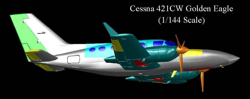
The images below show the 421CW on the tarmac…
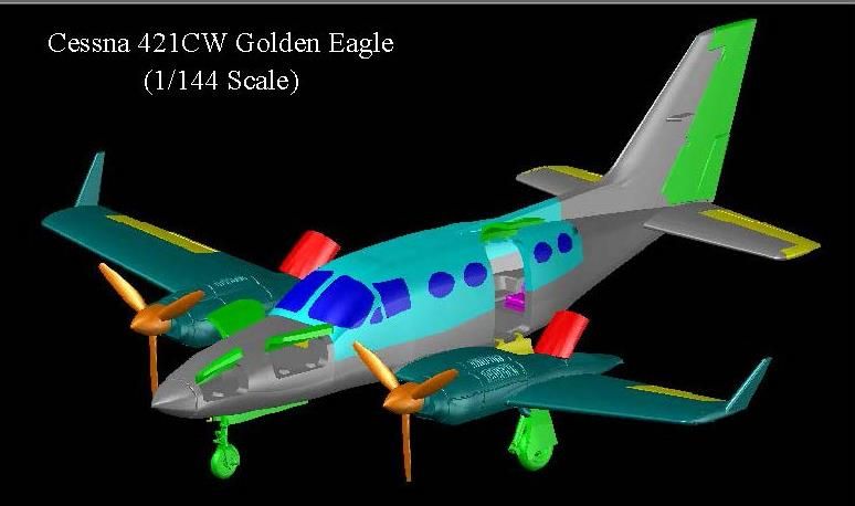
…And in flight with the gear retracted.
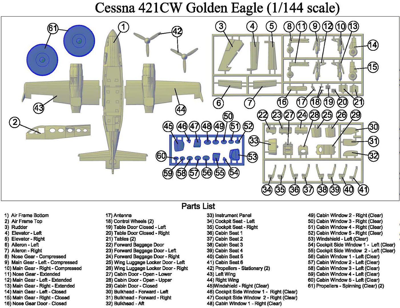
The image below shows the parts diagram for the 421CW.
Of course, I had to make decals for it, I couldn’t decide on color schemes, so I did two…
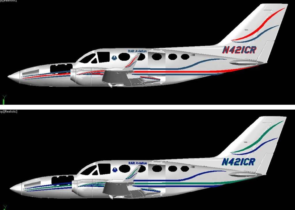
…And was having fun, so I decided to make a second scheme for the 421C too.
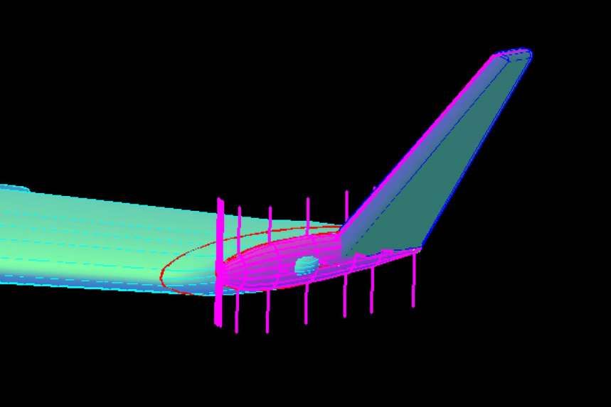
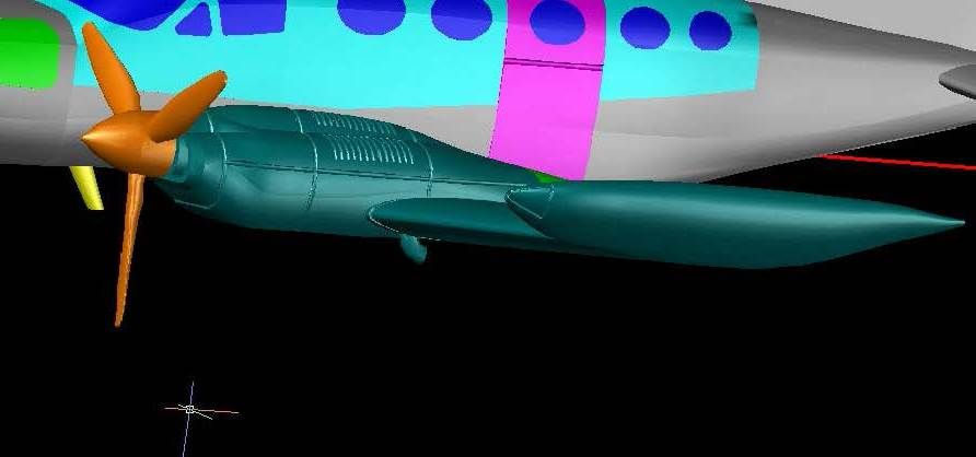
Converting the 421C to the 421B required adding the wingtip fuel tanks and redesigning the main gear. Making the wingtip tanks was tricky, as all I had to go on were some marginal 3-views, and a few pictures. I started by tracing the outline of the tank from the front view with an ellipse, shown in green in the image below. I figured this would be the fattest point of the tank. I also traced the top view of the tank using a polyline (also shown in green). I would have traced the side view, but it is so fuzzy, I couldn't really even tell where it is supposed to be.
With the outlines traced, the next thing I had to do was copy them to the right locations on the wing tip and rotate them into the proper planes. The tank section was moved so that the bottom of it was at the bottom center of the wing tip. When I rotated it 90 degrees it was at the right angle with respect to the wing. The top view outline I aligned so that the widest part was in the center of the wing where the section is the fattest.
This is where it got tricky. The top view is just that, a top view. The wing and the tank are at an angle to that plane, so the top view tracing shows the width of the tank, when looking straight down on it, and is not how wide it is, if that makes sense. When looking straight down on it, the outer and inner points of the initial ellipse lined up almost perfectly with the inner and outer lines of the top view tracing. That was a good sign, so the next thing I did was copy the ellipse numerous places forward and aft at right angles to the section. Then using the top view, again looking straight down on the model, I moved the ellipses out so that the most outside points were lined up with the outside tracing line. I then scaled the ellipses using these outside points until the most inner part of the ellipse matched the inner line. I then lofted between all of the sections, and discovered the shape was close but some of the sections on the ends were misaligned, so I moved them and re-lofted it. At this point, I liked the shape, but it was too big so I reduced it 90% and thought it looked better. I discovered later that I had mis-scaled the plans I based the design on by 10%, thus explaining the tank being over-sized. The image below shows the sections (magenta), after they have been scaled, and moved, that I used to make the tank, which was joined to the wing.

With the tank finished, I etched the wingtip light.
The gear and gear doors also had to be redone, to replace the trailing link landing gear, of the 421C, with the MLG oleo struts used on the 421B. This essentially meant redoing the entire gear, although I was able to use the wheels. The good thing is that I only had to do it once, then mirrored it to the other side. The image below shows the gear, with the compressed gear and door in position on the port side and the remaining gear and doors moved down for a better view of them, and although I changed the design slightly after this image was clipped, you get the idea.
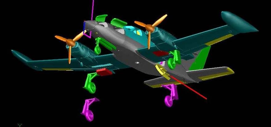
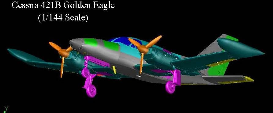
The image below shows the 421B, in flight with the extended gear.
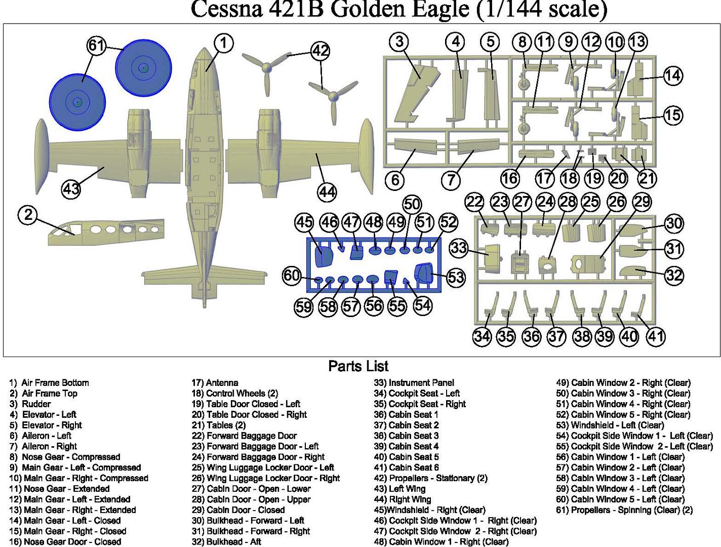
The conversion from the 421C to the 421CW did not require changing the frets, just replacing the wings, but the conversion from the 421C to the 421B, also required modifying the frets, i.e., cutting off the old gear and adding the new gear. The parts diagram for the 421B is shown below.
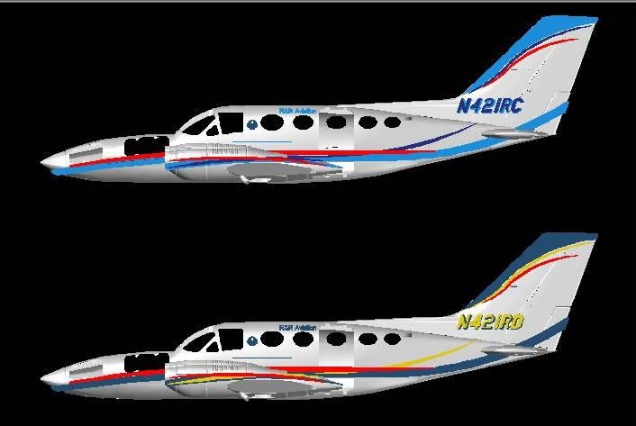
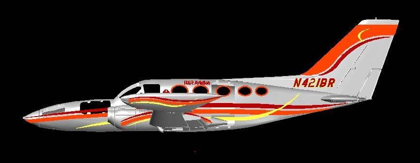
And, of course, once again, I had to make decals, for it. This time I just made one set (so far).
The 421A is in the works…