SEARCH FINESCALE.COM

Enter keywords or a search phrase below:

Sloop-of-war, PELICAN model scratch build.

9270 views
71 replies
1 rating 2 rating 3 rating 4 rating 5 rating
  • Member since
    June 2014
  • From: New Braunfels , Texas
Posted by Tanker - Builder on Monday, July 24, 2017 1:57 PM

Ay !

   Quite criticsizing yourself . I see a lot of work that says you are driven . Now that said I have to remind you .On your case , 3 to 4 inches on each end and 1 to 2 inches from any Yardarm tips .

 Oh , keep on keeping on , I love it .

fox
  • Member since
    January 2007
  • From: Narvon, Pa.
Posted by fox on Monday, July 24, 2017 2:36 PM

Great work! Toast  Thoroughly enjoying this build. Learned a lot so far and looking forward to learning a lot more.

Jim  Captain

 Main WIP: 

   On the Bench: Artesania Latina  (aka) Artists in the Latrine 1/75 Bluenose II

I keep hitting "escape", but I'm still here.

  • Member since
    December 2006
  • From: Jerome, Idaho, U.S.A.
Posted by crackers on Monday, July 24, 2017 4:40 PM


Thanks guys for your support. Appreciate your good input. As this thread is continued, the dialog will focus on how the completed hull was achieved to the stage where the rigging process will begin.

When the deck of the hull was completed, the next step would be to add the bulwark with the gunports. Cutting out this section would be impossible on wood, as the wood would splinter. Thus, sections of the bulwark would have to be cut and glued together like a puzzle, as is shown in the above picture. Before creating this bulwark from wood, a cardboard template was made on a trial run on the hull to see that the bulwark is a correct fit. The cardboard template is above the wooden template section.

The completed port and starboard bulwarks are in place. The holes between the gunports are for the insurtion of rowing sweeps on the real ship, to be used in calm weather.

When the bulwarks are in place, the next task is to make the black cap rail that goes on top of the bulwark. A piece of scap wood is needed. The overhead profile of both the port and starboard side of the hull is drawn on the scrap wood.  Penny nails are inserted along this line that is the correct width of the cap rail. Thin stips of wood that will bne the cap rail are soaked in hotwater with a touch of bleach. When this wood is completely soaked and plyable, it is VERY carefull bent between the nails and dried overnight. When the desired shaope of the cap rail is achieved after drying, it is painted with black acrylic and glued into place on top of the bulwark.

This is a closer view of the procedure outlined above. Perhaps this is a better explaination. The hull profile in cardboard with the penny coin for scale.

Here, the cap rail is glued in place on the port side of the model. To be continued.

Happy modeling    Crackers  ConfusedYes


Anthony V. Santos

  • Member since
    June 2007
Posted by jrb53 on Monday, July 24, 2017 5:47 PM

Glad the PELICAN is back and really enjoyed the wood bending class.  Before we get too far, I noticed the varied cannons.  Did you scratch build some of those?

Jack

  • Member since
    November 2005
  • From: Formerly Bryan, now Arlington, Texas
Posted by CapnMac82 on Monday, July 24, 2017 8:21 PM

crackers
how could this be accomplished with a skylight and companion way in place ? Would the crew have to have long legs to step over these structures ? Inquiring minds want to know.

According to the smart people, the fundamental answer is that you had enough men on enough bars to be able to let loose when there was a deck obstruction.

But, also remember that such things as sompanionways were built of panels that were just pegged to the ship, they could be struck down to clear the capstan.  Ditto the skylight.  Gratings to fill the holes was probably lashed up under the overhead below decks.

A windlas is similar, there's only about a 45º arc that the windlas bars can be heaved through, since you need room to pul them out before they touch the deck to be passed forward again.

The capstan was clearly superior to the windlass, as it could be "run" in either direct by merely reversing the pawl.  However, it was manpower intensive.  Slightly faster, too.  A windlass usually could only be worked by four men pulling, and having a mate to mind the pawl, and boys to pass the bars.

  • Member since
    December 2006
  • From: Jerome, Idaho, U.S.A.
Posted by crackers on Monday, July 24, 2017 9:10 PM

Thank you CapnMac82 on your explanation of the position of the capstan on the PELICAN model. On this warship model by Dan Holmes, the capstan is visable without protuding deck furniture obstruction. The grating can be walked on as long as crew members did not stub their toes as they trod across this deck feature.  Ship builders were practicable people by constructing common sense things, especially on warships, where efficiency was a necessity, especially during battle. When viewing the Harold Hahn plans of the PELICAN, the skylight and the companion way somehow did not seen logical as obstruction to the crew working the capstan. I was tempted to remove these obstacles, but decided to remain true to the Hahn plans. Any comment on this question ?

Happy modeling       Crackers  Indifferent   2 cents

Anthony V. Santos

  • Member since
    December 2006
  • From: Jerome, Idaho, U.S.A.
Posted by crackers on Friday, July 28, 2017 12:56 AM

Carving the PELICAN's launch and rowboat took some carving skills from a block of wood.

These are the tools that were needed for the carving procedure. Ising the elongated stick, a pencil drawing was made on the stick the basic outline of the craft, as noted on the Hahn plans. Most of the hollowing out of the boat was accomplished with my cordless Dremel drill aided with wood carving gouges.

Here is the PELICAN launch from the side view and the bottom view. The extra piece of wood attached to the stern of the launch is a holding grip that was held while carving the vessel. The Dremel drill with carving attachments did most of the carving work.

The top view of the launch. The right hand side of the picture is the paper ribs with a 10 mesh plastic canvas grating for the floor bottom of the launch. The penny denotes the scale of the carved launch.

  l

The hollowed out launch to be and the completed version at right. The penney is for scale.

The completed launch with the attached rowboat. The rowboat was the more difficult task, because of its small size after three attempts of carving. The determination of the depth of carving on both crafts was by holding the carving close to a naked light bulb. The brighter of the light shine through the carving indicated how close it would be to puncture through the wood.

To be continued.

Happy modeling     Crackers     Cool


Anthony V. Santos

  • Member since
    November 2009
  • From: Twin Cities of Minnesota
Posted by Don Stauffer on Friday, July 28, 2017 11:16 AM

Wondering who you are posting your images with. A click on image properties brings up a URL with staticflicker.  Can you tell us more?

Don Stauffer in Minnesota

  • Member since
    December 2006
  • From: Jerome, Idaho, U.S.A.
Posted by crackers on Friday, July 28, 2017 11:37 AM

Thanks Don for your reply. I take pictures with my Samson digital camera. Transfer the images to flicker gallery, where it is placed on the Finescale Modeler Furum.

Happy modeling       Crackers    Surprise

Anthony V. Santos

  • Member since
    December 2006
  • From: Jerome, Idaho, U.S.A.
Posted by crackers on Monday, August 21, 2017 10:54 PM

The name PELICAN on the stern of the ship. The ring under the letter "I" is for towing the ship's boat during battle, so that the vessel will not be shot to pieces, or the crew will have an escape craft should the PELICAN be in a sinking condition. The scroll work is made by squeezing very soft and malleable wire under a vice. It took a number of frustrating tries before the desired results were accomplished.

 The name PELICAN was set by 1/8th" size transfer letters, which I happend to find at a stationery store years ago. I do not know where to find this size lettering here locally.The transfer is accomplished by placing the desired letter over the intended surface and rubbing that letter with a blunt pointed dowl. Scrubbing has to be very thorough, or else parts of the intended letter will come up missing.

Happy modeling    Crackers   Stick out tongue

Anthony V. Santos

  • Member since
    December 2006
  • From: Jerome, Idaho, U.S.A.
Posted by crackers on Monday, August 21, 2017 11:14 PM

 The figurehead in place. Carving this item took plenty of patience with foul words in the background.

With hand carving chisesl, a rough outline of the figure was cut out following a pencil drawing on the rectangular stick. Then, the closer details followed by tools attached to my Dremel cordless drill. I prefer this drill, because there is not the problem of the power chore interferance.

Happy modeling     Crackers      Confused

Anthony V. Santos

  • Member since
    August 2007
  • From: back country of SO-CAL, at the birth place of Naval Aviation
Posted by DUSTER on Tuesday, August 22, 2017 5:03 PM

I gladly join in the enjoyment of watching the ship come together. Most impressive and your explanations make the process understandable and interesting for me, an old plastic modeler.


Steve

Building the perfect model---just not quite yet  Confused

fox
  • Member since
    January 2007
  • From: Narvon, Pa.
Posted by fox on Wednesday, August 23, 2017 7:50 PM

You are doing some very fine work here Anthony! This is going to be a great looking ship.

Jim  Captain

 Main WIP: 

   On the Bench: Artesania Latina  (aka) Artists in the Latrine 1/75 Bluenose II

I keep hitting "escape", but I'm still here.

  • Member since
    December 2006
  • From: Jerome, Idaho, U.S.A.
Posted by crackers on Monday, August 28, 2017 11:19 PM

Ship model purests might blanch and wince when they realize what was used for belaying pins on the belaying rack of the model.

It was the trim tips of the bristles of a common household broom. The bristles are yellow to simulate wood and are the right size for scale on the belaying rack. Granted, this material is unusual, but it seem to fill its role as intended.  To be continued.

happy modeling    CrackersSad

Anthony V. Santos

  • Member since
    December 2006
  • From: Jerome, Idaho, U.S.A.
Posted by crackers on Monday, August 28, 2017 11:51 PM

Anthony V. Santos

  • Member since
    December 2006
  • From: Jerome, Idaho, U.S.A.
Posted by crackers on Thursday, August 31, 2017 7:00 PM

Windless in temporary place on the deck of the PELICAN. A cannon ball rack can be seen next to a cannon. Ther cannon balls are pellets from a shotgun shell for bird hunting.

Scratch built windless for the scratch built model. The eyelets from an old boot will be shaped in place on the bow of the PELICAN to represend the hause hole cover. The inner end of metal of the hause was connected in a bolster in order to give the anchor cable a smoother run by minimising chafe and protected the cable from nipping on a sharp edge when the ship rode at anchor. While at sea, the hause hold was often plugged to prevent heavy bow waves from entering the foreward part of the deck. The ship's bell on the top of the windless was shaped from another boot eyelet.

Happy modeling   To be continued       Crackers    Cool

Anthony V. Santos

  • Member since
    July 2013
Posted by steve5 on Friday, September 1, 2017 12:35 AM

nice work cracker's , enjoying this build .

steve5


  • Member since
    July 2014
  • From: Philadelphia Pa
Posted by Nino on Friday, September 1, 2017 10:51 PM

RE:  "...balsa hull of the Revenue Cutter MORRIS from an old Ideal Model Ship Construction set.   ... , then it would be planked with 1/4 inch popsicle stick planks cut from my Micro-Mark hobby table saw. I have always thought popsicle sticks would make nice planks, since they are clear and blemish free."


Thanks for this great "How-To" build.                                                                               I already started saving my grandkids popcicle sticks.

 Were the Guns part of the original kit?  They sure look to scale.

       Jim.


  • Member since
    December 2006
  • From: Jerome, Idaho, U.S.A.
Posted by crackers on Friday, September 1, 2017 11:51 PM

Thanks for your reply, Jim   No, the guns are not from a kit. They are plastic figures that my wife collected from a location she does not remember. On a stroke of good fortune, these figures happen to be at the scale for the PELICAN's cannons. The cannons werte modified to be replicated for the ship's armament

Happy modeling    CrackersHuh?

Anthony V. Santos

  • Member since
    July 2014
  • From: Philadelphia Pa
Posted by Nino on Saturday, September 2, 2017 8:27 AM
I followed many of your postings over the years. Good to see you back.
  • Member since
    December 2006
  • From: Jerome, Idaho, U.S.A.
Posted by crackers on Sunday, September 10, 2017 9:58 PM

My cannons are ready after being selected from an unusual source. Over the years, my wife collects items for her hobby. Years ago, she acquired some plastic figures which she does not remember what they are used for, so they were put aside and forgotten. When I mentioned that the model of the PELICAN required cannons, she remember her plastic figures, who were otherwise useless.

Perhaps some of you on the Forum can tell me what these figures represent. The cannon on the right is 3/4" long on the barrel, which is just right for the correct scale required for the PELICAN model. When adjusted, the cannon fits snugly under the gun port of the model.

The plastic cannon on the left is trimmed of its wheels and the rear support as shown on the second grey cannon. The armament is painted black on the barrel and brown on the carrage. Wampum beads are painted and glued for wheels. The last cannon of britania metal is what is available at Bluejacket Shipcrafters for $3.70 each, times 18, the number of cannons required on the model, which adds up to a sizable chunch out of my meager budget. The redone plastic cannons may not be correct, but the savings is worth the effort.   To be continued.

Happy modeling      CrackersSurprise


Anthony V. Santos

  • Member since
    December 2006
  • From: Jerome, Idaho, U.S.A.
Posted by crackers on Tuesday, October 17, 2017 1:47 AM

MASTING, RIGGING WITH SAILS of the HMS PELICAN.

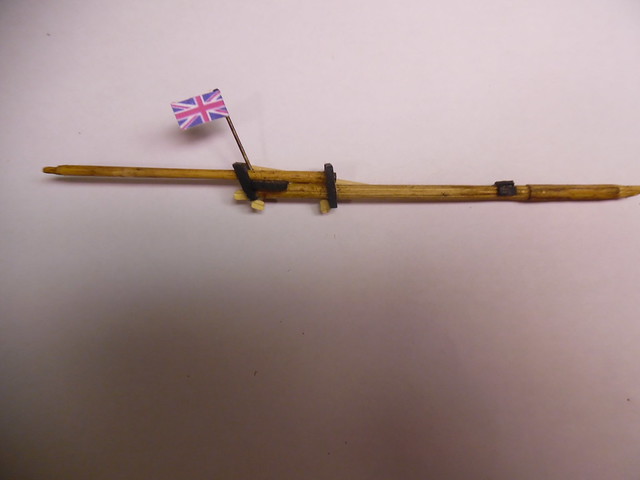
Now that all the elements of the hull construction has been completed, it's time to begin masting, rigging and sail attachment of the model. Starting from the bow to work toward the stern of the model, the bowsprit is constructed with the Union Jack flag attached to its staff. Block pullies for the sprit sail is attached to the cap, painted black, as well, as the bee block for rigging when the sprit sail is in place. The bowsprit's heel is is placed in line with the foremast and supported by the stem, to situated its length exactly on the center line of the ship like all the other masts.

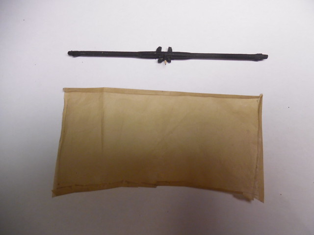
The sprit sail yard, painted back like most of the British ships of that period, is now ready to receive its sail, after the sail has been sewn with reef points, yard lashings, clew loops and cringles. The model sail is made from slikspan dyed with light brown acrylic paint diluted in water, then dried.

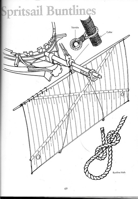
The main source of model rigging and masting has been "Rigging Period Ship Models" by Lennarth Petersson. This publication is a gold mine of drawings and diagrams which show how each separate item of both standing and running rigging is fitted to the masts, yards, and sails. On page 69, is an illustration of the sprit sail on the bowsprit. Making the "X" style of reef points as featured on this illustration, will be a challenge. Instead of this configuration, it would seem that the reef points would be arrayed in a horizontal manner to be bent to the sprit sail yard. Perhaps someone on the Forum could explain why the sprit sail reef points are as seen on this illustration.

Happy modeling      Crackers    Embarrassed


Anthony V. Santos

  • Member since
    September 2005
  • From: Groton, CT
Posted by warshipguy on Tuesday, October 17, 2017 5:49 AM

Crackers,

Excellent job so far!

Bill

  • Member since
    September 2012
Posted by GMorrison on Tuesday, October 17, 2017 7:11 PM

Anthony, very nice work.

I don't know the answer to your question, but I have an idea that I think is right.

The bottom of the sail is pretty close to the water. The spritsail would be set only when sailing downwind, the ship will be on one tack or the other, and therefore heeled over to one side or the other. Especially one with a schooner rig.

By reefing the bottom of the sail at an angle, it would keep the leeward bottom corner of the sail out of the water. This means changing the reef when tacking, but in a downwind tack where a spritsail is set and the little ship is on a run, tacking wouldn't be something that happens too often.

But dragging a sail in the water will really slow you down.

 Modeling is an excuse to buy books.


  • Member since
    December 2006
  • From: Jerome, Idaho, U.S.A.
Posted by crackers on Tuesday, October 17, 2017 11:38 PM

G Morrison, thanks for the advice on why the reef points on the sprit sail is displayed in an "X" arrangement. Your logic is certainly correct on why the sprit sail is reefed in this manner to prevent dragging on the water surface. On some sprit sails, circular holes were placed on each lower corner of the sail to drain collected water. So, your suggestion certainly merits practical value.

Happy modeling         Crackers     Smile

Anthony V. Santos

  • Member since
    July 2013
Posted by steve5 on Wednesday, October 18, 2017 1:39 AM

I've often wondered that myself , thank's gmorrison , love what you are doing cracker's


  • Member since
    December 2006
  • From: Jerome, Idaho, U.S.A.
Posted by crackers on Sunday, December 15, 2019 2:30 PM

After a two year hiatus, I am to continue the PELICAN project. I got burned out modeling and put the project aside. I had no idea it would take so long for me to make up my mind. I promise to continue to the final end on this project when it is completed.

To continue my project is to work on the spirit yard that is attached to the bowsprit. This yard is painted black as was the custom on some Royal Navy sailing ships. To attched the foot ropes, the yard is scotch taped to a surface. Next, black sewing thread is soaked in glue and pulled into a straight line and allowed to dry as stiff as wire.

The ends of the foot ropes were tied to the yard, but others were glued in place and trimed. Trying to knot these ends would have been more that I could achieve. The actual sail for this yard will be attached after the sail reef points have been attached to the sail. My next post will be how I make reef points on sails.

Happy modeling   Crackers   Smile

Anthony V. Santos

  • Member since
    October 2019
  • From: New Braunfels, Texas
Posted by Tanker-Builder on Friday, December 20, 2019 1:22 PM

Note,You ARE being watched sir !

  • Member since
    October 2019
  • From: New Braunfels, Texas
Posted by Tanker-Builder on Friday, December 20, 2019 1:27 PM

Oho!

      Looking at this confirms just what I thought .Yer as Nuts as the rest of us! Nice Work there! T.B. P.S. Ships weren't built to accomodate the crew remember. So if they twist an ankle  while on the capstan, Oh Well !

  • Member since
    December 2006
  • From: Jerome, Idaho, U.S.A.
Posted by crackers on Friday, December 20, 2019 5:39 PM

Twisting an ankle while pushing on a capstan bar is small hurt. Falling from the yard arm by missing the foot ropes could cause major damage to one's life. With my fear of heights, only the barrel of a gun pointed in my direction could get me up there.

Happy modeling   Crackers   Indifferent

Anthony V. Santos

JOIN OUR COMMUNITY!

Our community is FREE to join. To participate you must either login or register for an account.

SEARCH FORUMS
FREE NEWSLETTER
By signing up you may also receive reader surveys and occasional special offers. We do not sell, rent or trade our email lists. View our Privacy Policy.