Update 15 – 11/15/2014
Good Morning Fellow Modelers!
No sweat Straycat1911, my eyes glaze over often too. Although there will be a test. :o)
I wondered if people could follow it or not, or if they were even interested, but I figured there might be a few really bored people that would. My guess is that most people that happen onto the thread just look at the images. I suppose I could find out by pulling a trick an ex-boss of mine from years ago pulled. He was sure that his boss never read what he wrote, so one time he wrote something pretty offensive in a report to see. Unfortunately, he was right, and it got distributed to the state legislature unedited. It was not a pretty scene, so on second thought… perhaps not.
I post my WIPs because a while back I decided to post a WIP of a ship model I was building and quickly learned that, in the process of preparing the updates, I often discovered mistakes I hadn’t noticed before, because, as they say, “The camera is a harsh mistress.” I have found the same to be true with CAD models, even though there is no camera, just the “PrntScr” button. Also, I find it interesting and thought there might be others who do too.
Anyway Straycat1911, I will indeed be posting them on C2D, but be warned they aren’t going to be cheap. The 1/350 scale F-5’s I made are just under $25, and I imagine that the A-4’s will probably be about the same. Unfortunately, high cost is the main drawback of 3D printing at this time. The machines are really expensive, as are the material costs, and I know of at least one modeling company that got a 3D printer and is having to give it up because “it isn’t pulling its weight”. Someday the cost will come down, but not anytime real soon, I don’t think.
So, today’s update starts with a modification to the IFF antenna making it “boxier” to better match pictures found on-line.
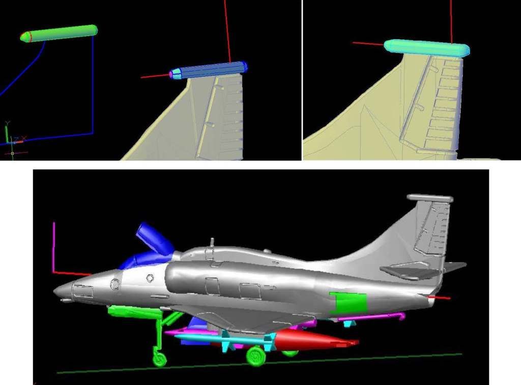
Next, I added the lower of the two features near the exhaust pipe (Does anybody know what they are?) using the Aviation News plans and pictures. This was less straightforward than it might have otherwise been due to a slight discrepancy in the plans. The upper left image below shows the tracings, polylines and circles I prepared to make the object. The upper right image shows it after I rotated the polylines and circles and lofted them. Because of the plan misalignment I had to move the solid up and to the left to match the model. The lower left image shows it moved and the tailhook layer turned on. Oops! To fix it, I first tried just shortening the new object, but then it looked too short compared to pix. So, I split the difference, shortening both the tailhook and object, as seen in the lower right image.
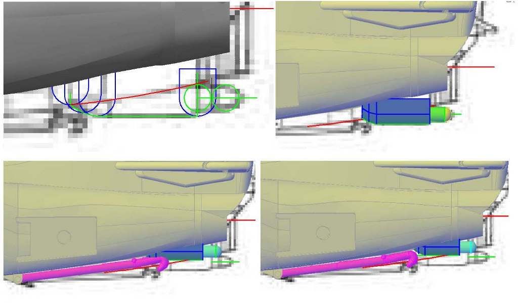
The image below shows it joined to the airframe.
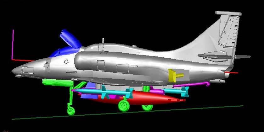
Next I added the features on the upper portion of the exhaust pipe as seen below. Again, I don’t know what they are.
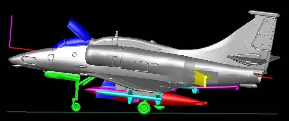
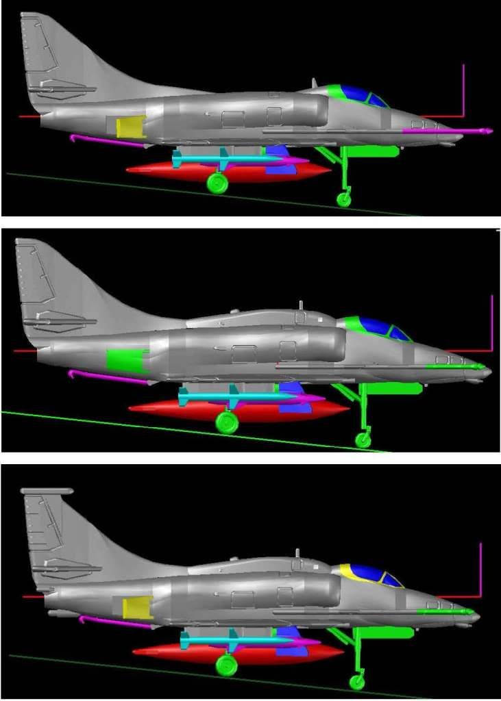
Next, I redid the canopy, but got into it and didn’t document the process. The images below show top to bottom, the A-4E, the A-4F and the A-4M. That leaves only the TA-4F, which is going to take some doing.
