SEARCH FINESCALE.COM

Enter keywords or a search phrase below:

1/350 Scale McDonnell Douglas A-4 Skyhawk

35319 views
62 replies
1 rating 2 rating 3 rating 4 rating 5 rating
  • Member since
    March 2012
1/350 Scale McDonnell Douglas A-4 Skyhawk
Posted by Rdutnell on Thursday, November 6, 2014 12:52 PM

Greetings All!

My name is Russ, and I have recently gotten into making models using AutoCad and 3-D printing.  It started with a display I made for my dad of the planes he flew during his career in the United States Air Force.

“A Career in Flight” – 3D Printed 1/350 Scale Aircraft Display (Work in Progress) - http://cs.finescale.com/fsm/modeling_subjects/f/2/t/157366.aspx

Through this post, I met Ron, and we have collaborated on several “projects” that are posted elsewhere on this Forum, including:

1/144 Scale Luscombe 8A Silvaire  - http://cs.finescale.com/fsm/modeling_subjects/f/48/t/158982.aspx

1/350 and 1/144 Scale Cessna 310B - http://cs.finescale.com/fsm/modeling_subjects/f/48/t/159017.aspx

1/350 Scale Gulfstream IV-SP - http://cs.finescale.com/fsm/modeling_subjects/f/48/t/159041.aspx

1/144 Scale Spartan 7W Executive - http://cs.finescale.com/fsm/modeling_subjects/f/48/t/160518.aspx

1/144 Scale McDonnell F-4K Phantom FG.Mk1 and F-4M Phantom FGR.Mk2 - http://cs.finescale.com/fsm/modeling_subjects/f/2/t/160249.aspx

1/144 Scale Lake LA-250 Renegade - http://cs.finescale.com/fsm/modeling_subjects/f/48/p/162598/1772871.aspx#1772871

1/144 Scale Cessna 421C Golden Eagle - http://cs.finescale.com/fsm/modeling_subjects/f/48/t/162600.aspx

1/350 Scale Aircraft Diorama - http://cs.finescale.com/fsm/modeling_subjects/f/19/t/161594.aspx

This thread will show the process used to make a 1/350 Scale model of the McDonnell Douglas A-4 Skyhawk.

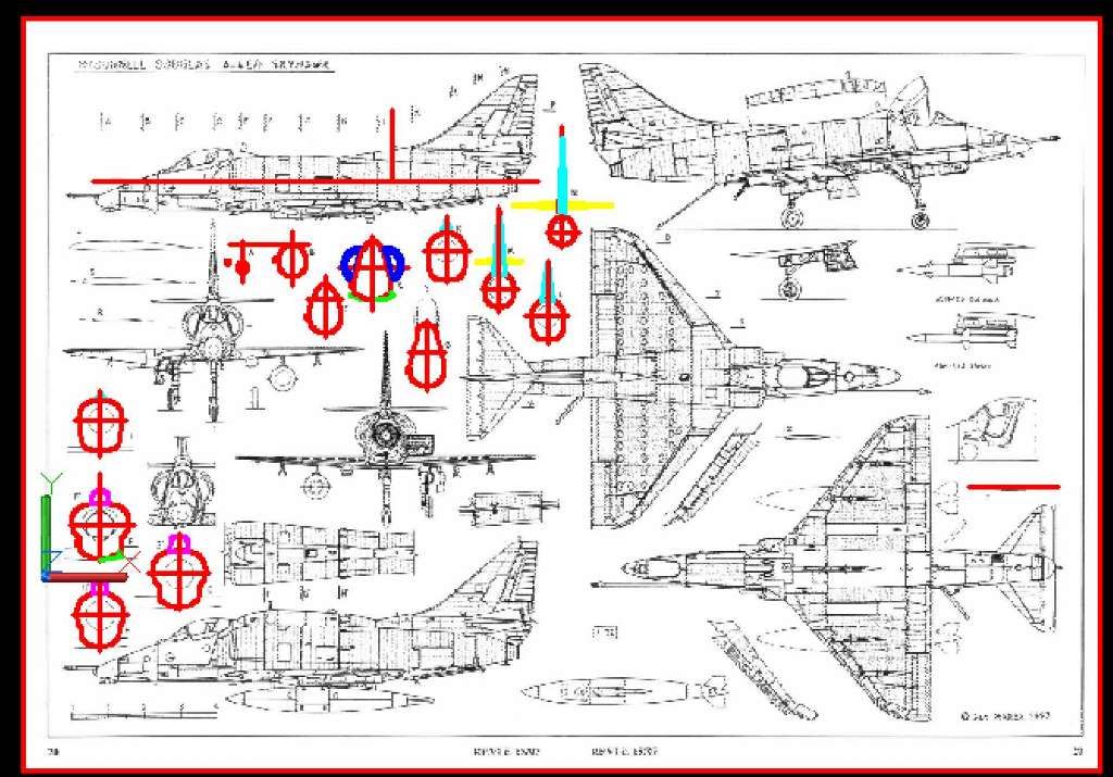
As usual, the first thing I did was search the internet for plans, which I then downloaded, imported into AutoCad, and scaled to size.  For this model, I found two sets of plans, one of the A-4F/E by Jan Merek, and another from Aviation News showing the A-4E, A-4M and the TA-4F.  I started with the Merek plans because they are of slightly better print quality and have more cross-sections.

The next thing I did was trace the outlines of the airframe cross-sections, as shown below.
                       

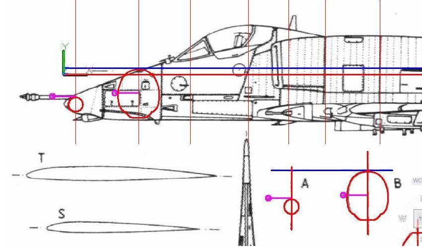
The next step was to copy the sections to their proper places on the side view.  In the image below, you can see that the reference lines on the sections didn't always line up with the reference line on the side view, and I had to move them either up or down slightly.  In a few cases, the section's size was off a tad (the lines at the top and bottom didn't match).  In these cases, I moved the section so that the bottoms matched, and scaled the section up until the tops matched too.
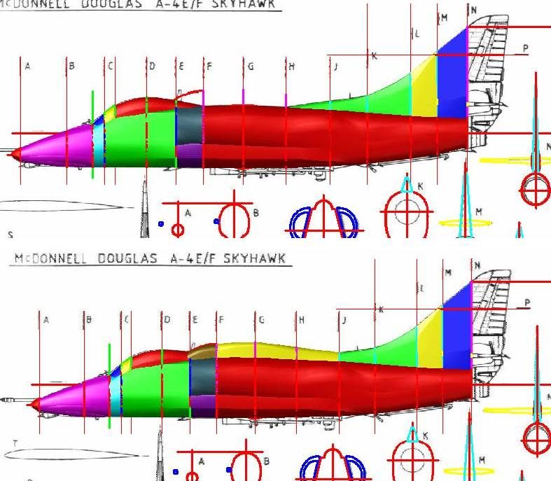
The image below shows it after I have copied all of the sections to the side view, and modified them as needed.  Notice that on some of the sections I broke them into 2 different sections.  This is because I have found that splitting the parts up gives me more control of the shape, and I can later join the shapes together.


With the sections in position, I rotated the sections 90o about their vertical axes.  I then used a combination of Loft and Extrude Commands, to turn the sections into “solids”.  The image below shows all of the various solids (except the forward part of the engine cowling section on the right side) that I made from the sections.  Note that I had to add 2 sections (between B & C and between C & D) to get the shape right in these areas, and I had to adlib the nose.  The top image shows the E without the hump and the lower image shows the hump, that according to the Merek plans was on the A-4F, and according to the Aviation News plans was on the A-4M.


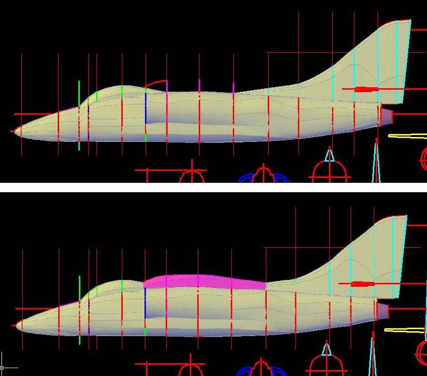
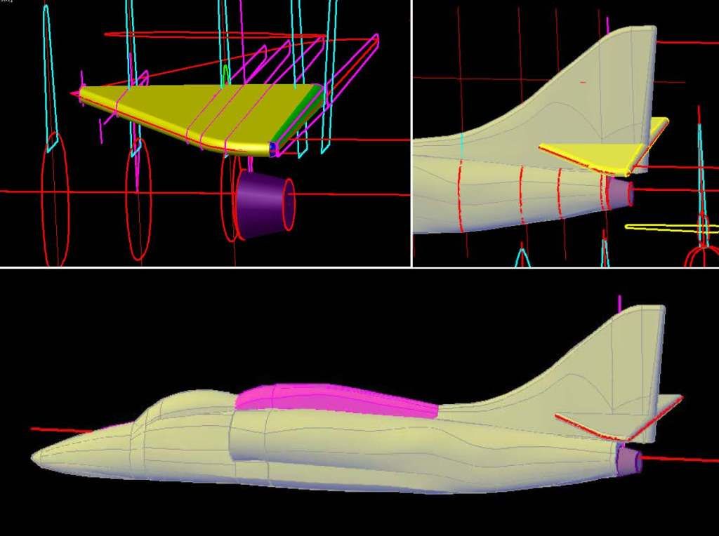
Because the model is in 1/350 scale, I had to make the tail thicker than it really is so that it will both print, and be durable enough to survive handling during cleaning, painting and assembly, as well as shipping.  Although it is difficult to see, the images below show the tail before (top) and after (bottom) I modified the sections to make the tail thicker.  Note that the port side horizontal stabilizer has also been started.  The “solid” part was generated using the sections, the outline is from the top view that I have traced copied and rotated.  The exhaust nozzle may also be seen.

At this point, I joined the airframe parts and tail together.  I also joined the hump parts together, but did not join them at this point.  This will be done later to make multiple versions.

The next set of images show the construction of the stabilizers, which, like the tail were made thicker than the plans show. In this case I did one side than used the mirror command for the other side.  The lower image shows it after I have joined it to the airframe.
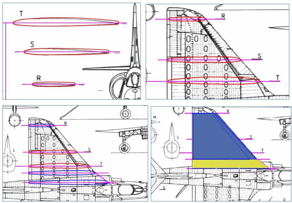
Next, I did the wings.  In the set of images below, you can see the tracings I made of the wings (top left).  Note that I made the aft ends thicker than the plans.  The image at top right shows the sections copied to the wing on the top view.  Note that the alignment isn’t perfect and required slight modification.  Also, in order to actually make the wing, I needed more sections than provided, so I copied the T-section and modified it, to create the blue sections shown in the lower left image.  The image at lower right shows it after I rotated and joined the blue sections.
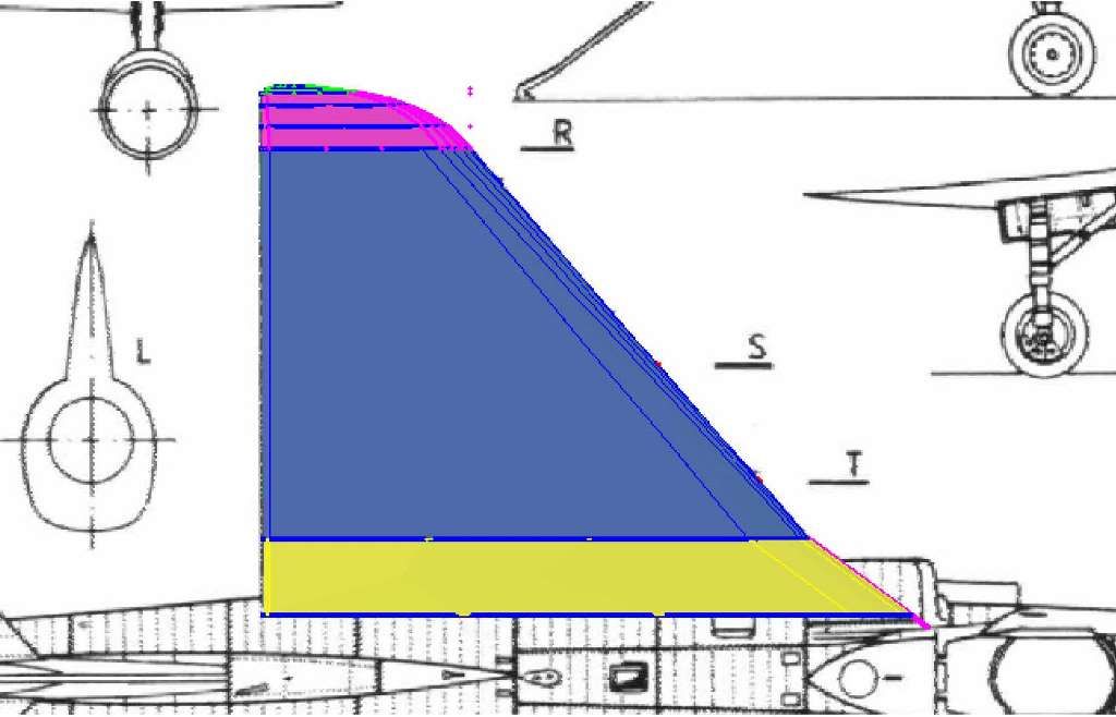
To make the tip I copied and scaled section R to match the top view and lofted them together, as seen below.
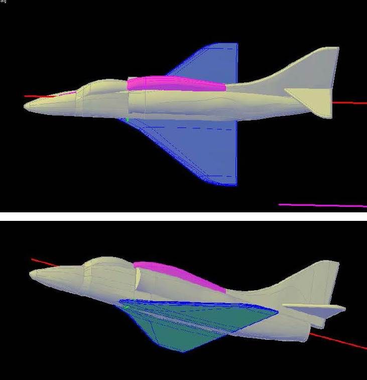
At this point, I joined the pieces together and mirrored it.  I then had to copy it to the airframe side view and rotate it to the proper orientation.  I later joined them to the airframe.
With the basic shape completed, the next thing to do was to start detailing.  Stay tuned…

  • Member since
    March 2012
Posted by Rdutnell on Thursday, November 6, 2014 3:27 PM

Update 1

Continuing from my previous post…

With the basic shape of the airframe completed, I started on the detailing, beginning with the tail.  Looking at photographs of A-4’s, it may be seen that the A-4 tail is somewhat unique, in that it has a pattern of raised and lowered surfaces on the rudder.  I traced these areas from the plans and then extruded them into the rudder slightly (0.004” to be exact) as shown in the upper left image below.  The upper right image shows it after I subtracted these extrusions from the airframe.  Next I projected the traced outline of the rudder onto the surface and extruded 0.008” diameter circles along the projected lines to create solid tubes on the surface as seen in the lower left image.  This tube was then subtracted from the airframe, as shown in the lower right image.

Another somewhat unique feature of A-4’s is the raised areas where the horizontal stabilizers attach to the tail, below the rudder.  To make it I first traced the outline from the plans then made copies of it that I scaled down in size, then moved these copies out, so that the sections got progressively smaller, then lofted them as shown in the top two images below.  The lower image shows it after I joined these bits to the rest of the airframe.

At this point I noticed, from looking at pictures, that I didn’t have the outline of the rudder quite right, so I redid it.  You can the difference by comparing the image below with the one above.

Next I did the engine intake.  To make it I copied the outline I had traced from Section E forward then scaled them down as moving forward to match the tracing from the plans.  These sections were lofted together as shown in the image below.  The green polyline seen in the image was then extruded about half way into the shape and subtracted to hollow out the intake.  Note that the opening is smaller than it should be to assure adequate thickness of the sides for proper printing and durability.

The image below shows the model at this point.

The next thing I did was “etch” the outlines of the elevators. Again using 0.008” diameter circles extruded along lines projected onto the surface from tracings of the outline from the plans.  Of course, the tracings first had to be copied from the top view, where they were traced, to the side view, where the model is, then rotated to be in proper alignment.  The image below shows the tubes, before I used the Subtract command to “etch” them in.  Once again, due to symmetry, I just made one, then used the Mirror command to make the other side.

I did the same thing for the wings, as seen below.

To be continued…

  • Member since
    September 2012
Posted by GMorrison on Thursday, November 6, 2014 3:50 PM

You are posting in the wrong forum.

Get Tim to switch you over to aircraft.

 Modeling is an excuse to buy books.


  • Member since
    March 2012
Posted by Rdutnell on Thursday, November 6, 2014 3:56 PM

Thanks GMorrison! I'll ask him to change it.

  • Member since
    March 2012
Posted by Rdutnell on Friday, November 7, 2014 10:28 AM

Update 2

Good Morning All!

Continuing where I left off, the next thing I did was the engine nozzle area.  To make the top shield(?) I used the tracing from Section N, and extruded it back.  I then sliced the aft end using a tracing from the side view.  Next I made the nozzle itself by extruding a circle that match the diameter of the lower part of Section N.  I used the plans to get the location and diameter for the aft end, then lofted the circle together.  The last step was to hollow it out.  The images below show the resulting shapes, before I joined them to the rest of the airframe…


…And after I joined them.


At this point I did a little investigation into doing more than one version of the aircraft.  The images below show the model as designed on the Marek plans on top.  The lower image shows the airframe copied to the A-4E on the Aviation News plans.  You can see that the alignment matches almost spot on.


The top image below shows the airframe and hump copied to the A-4M on the Aviation News plans.  The alignment is good for the most part, but deviates slightly at the aft end of the canopy and at the extreme aft end of the airframe, on the bottom.  Still, at this scale, I think what I have will work.  The lower image shows the airframe on the TA-4F on the Aviation News plans.  I have cut the airframe just in front of the canopy, and moved the aft section back so that the tail tip matches the drawing.  You can see that the alignment is pretty good, but the top of the fuselage is a bit higher on the plans than on the model.  Still, I think it would all be useable, and the hardest part would be making the larger canopy due to the back seat.

One of the decisions I have to make for every model I make is how much detailing to add.  Often, this is limited by the quality of the plans I find, but that is not the case with this model.  In fact, in this case the plans are almost over detailed, at least for 1/350 scale.  Because of the small size, the “etched” lines are over-sized, and if I did every line shown on the plans, the model would be nothing but etched grooves.  The trick is including the “important” or more dominant features, and ignoring the rest.  The hard part, especially since I have limited knowledge about airplanes, is determining what those are. 

The top image below shows the features I am going to include on the sides.  There will likely be a few more traced from the top view, but I’ll deal with that later.  The lower image shows it after I projected the tracings onto the airframe and put the outlines on a Temp layer that is turned off.  Not all of the features will require using the projected lines, but I usually do it so I can better see where they will be on the airframe.  Sometimes I have to move, or resize it slightly to better fit my model, but that doesn’t appear to be the case here, as everything seems to look good.

That’s it for now.

CHEERS!!!

  • Member since
    March 2012
Posted by Rdutnell on Saturday, November 8, 2014 6:52 AM

Update 3

The journey continues…, with this post showing how I made the speed brakes.

I started by moving the tracing shown previously out away from the airframe, but as close as possible without intersecting the surface.  I then drew lines between the corners of the lines previously projected onto the airframe, and used those points to establish a plane for my coordinate system.  I then rotated the outline so that it was on this plane.  This allows for the extrusion to go into the airframe more or less perpendicular to the surface.  The top left image in the set of images shown below shows the speed brake after I have projected it into the surface, so that it extended 0.0125” into the airframe at the narrowest point.  Next I copied the airframe, speed brake and reference line up out of the way (top right), then used the Intersect command on the copied pieces, and the Subtract command to remove the original extruded “solid” from the airframe.  The lower left image shows it after this was done and the speed brake had been mirrored about the central axis.  As with all of my models, I like to make them so they can be displayed in various ways, so the next step was to make the extended (engaged? activated?...) version.  To do this I first traced the angle of the open door from the top view plans, and moved it to the corner of the hinge on the brake, as shown in the lower right image.


 The upper left image below, shows it after I have rotated the angle tracing 90o to align it properly.  I then realigned my coordinate system to a line drawn between the end points of the hinges, and used the Rotate/Copy Command and the reference angle to make the engaged brake (upper right).  The lower left image shows the parts (coped up and out of the way again), after I have sliced the closed brake to make the hinge for the engaged brake.  To make the extender arm(?) for the brake I drew a 0.02” diameter circle in the center of the inside face of the closed door (lower right)…

…And another 0.02” diameter circle in the center of the inside face of the open door as shown in the upper left image below.  I then lofted between the circles, and extruded the inside circle inwards 0.01”, the latter to creating mating tabs for the brakes.  In the upper right image below, the inside door has been deleted, and the extruded bit has been mirrored to the other side.  The lower left image shows it after I joined the respective parts together to form the two versions.  To make the mating holes in the airframe to accommodate the tabs, I extruded 0.022” diameter holes from the ends of the tabs out away from the airframe, as shown in the lower right image.


I then moved the brakes and extrusions down to the airframe (upper left below) and subtracted the extrusions from the airframe (upper right).  The lower left image shows the engaged brake moved out slightly to show the recessed hole in the airframe.  The lower right shows the engaged speed brakes from the aft end.  Note: I put the brakes on different layers and the closed brake layer is turned off.

Cheers!

  • Member since
    March 2012
Posted by Rdutnell on Saturday, November 8, 2014 8:06 AM

Update 4 – 11/8/2014

Good Morning Again!

I don’t know if anybody is following this thread, but if you are, and you see something that isn’t right, please let me know.  I have no personal experience with A-4’s and am relying completely on the plans and pictures I find on-line, and can use any help I can get.

Continuing on the airframe detailing, the next set of images show the air intake on the side of the engine nacelle.  Using the projected tracing of the intake, I drew a rectangle sized in the vertical direction to match the outline, and in the horizontal direction to match pictures.  I then copied the rectangle aft multiple times, scaling and moving them as necessary to get the desired shape (upper right).  After a couple of attempts, I came up with a shape I was happy with (lower left), mirrored it to the other side and joined it to the airframe (lower right).


Next, I made the “tubes” for cutting out what appear to be access doors (upper left below), subtracted them and made the air intake and light for the hump (upper right).  The intake is just a scaled down version of the previous intake, repositioned and aligned to match the surface. The light was made by revolving an elliptical shaped polyline creating an egg shaped solid.  I also made tubes for yet another access door (lower left), then added the solids and subtracted the tubes (lower right).  Note the antenna has not been attached.  This is because I haven’t decided if I should include it or not.

With the hump detailing completed, I turned its layer off and added the vents(?) on top of the nacelle.  These vents are visible on the side view plans, but I used tracings from the top view, because I think they better show the shape and location of the vents.  I considered adding a couple of other features on top, but none looked more prominent than the others and I felt that if I did one, I would have to do them all, and then I would be back in the all groove thang.  :o)  Not good.  The upper image below shows the tubes for the vents.  The upper right image shows them subtracted, and the start of the little winglet just below the engine intake.  In the lower left image, I have added the tube for the round access plate(?) below the cockpit.  I also modified the winglet somewhat.  The lower right image shows it with the tubes for the round plate subtracted, and the solid prepared for cutting out what appears to be another air intake opening.  Again, I haven’t decided if I should include the winglet or not, because it is considerably over thick compared to the real deal.  I don’t know if the model would look better with or without it.  Any thoughts?

The images below show more of the same as I continued etching features into the airframe.  I haven’t done the red circle in the middle yet, because it falls right on the section line at the forward edge of the canopy, and I have to cut it here for the TA-4F, and I’m not ready to do that quite yet.

The images below show the current model with and without the hump.

CHEERS!!!

  • Member since
    December 2002
  • From: Lyons Colorado, USA
Posted by Ray Marotta on Saturday, November 8, 2014 9:29 AM

This IS the Aircraft forum...

 ]


  • Member since
    March 2012
Posted by Rdutnell on Saturday, November 8, 2014 9:33 AM

They moved it for me.

  • Member since
    March 2012
Posted by Rdutnell on Saturday, November 8, 2014 6:54 PM

Update 5

Hi All!

This afternoon I decided to start on the gear doors.  As usual, I started by tracing the outline from the plans, as seen in the images below.  I traced the nose gear doors, and they were slightly off center, so I moved them to the center line.  While looking at pictures, I noticed that there is a hump on the underside of the wing that runs through the main gear doors, so I traced both the hump outlines and the doors one the port side and mirrored them to the starboard side.  When I did, the alignment was off quite a bit, so I adjusted them slightly to center them.  When I was happy with them, I copied them up to a reference system below the airframe.


Looking at the bottom view (upper left image below) you can see that the alignment with the model was good, so I projected the lines onto the airframe (upper right).  To make the hump I drew a series of differing sized ellipses along the projected centerline for the hump (lower left) and lofted them (lower right)

I then prepared a tube around it to cut out the etching for the flap (upper left below), and mirrored the hump and tube to the other side (upper right).  I then subtracted the tubes and joined the humps to the airframe as seen in the lower image below.

With the humps completed, I extruded the door outlines into the airframe, and then copied the extruded doors and airframe up out of the way (upper left).  I then used the intersect command on the forward port side door and airframe (upper right), copied the airframe up again (lower left) and used the intersect command on the aft port side door (lower right)


At this point I could have repeated that process for the starboard side, but instead I deleted the “blocks” and mirrored the doors just created from the port side (upper left below).  Next, I cut out the recesses in the airframe, using the Subtract command (upper right).  To make the closed doors, I copied the four doors down slightly and joined them together (lower left), and then prepared tubes to etch the line between the two doors (lower right).

After this, I subtracted the tubes from the closed door pieces and moved them down to the airframe (upper right below, the upper left image is an accidental duplicate).  I then put the closed doors on their own layer and turned it off, moved the open doors down and rotated the port side doors into the open position (lower left), and mirrored them to the starboard side (lower right).

Cheers!!!

  • Member since
    November 2003
  • From: State of Mississippi. State motto: Virtute et armis (By valor and arms)
Posted by mississippivol on Saturday, November 8, 2014 10:36 PM

Very cool! You're 3D printing this, is that correct?

  • Member since
    March 2012
Posted by Rdutnell on Sunday, November 9, 2014 12:52 PM

Update 6

I’m glad you like it mississippisvol.  I am indeed making the model(s) for 3D printing.

The next thing I did was outline the panel in front of the tail hook and the tail hook itself on the bottom view plans, as shown in the upper left image, below.  The plans show 2 lines on the outer edge of the panels, and I wasn’t sure which one I wanted to use, so I traced them both.  Note that you can also see the angle tracing I used to make the engaged speed brake.  As before, I copied the tracings to just below the airframe (upper right), and rotated them 90o, as shown in the bottom view image at lower left.  The image at lower right shows it after I have projected the tracings onto the airframe… and discovered I had a problem in the design, with the tracings crossing the aft end of the wings.


Fixing this took some effort.  In the upper left image below, the sections on the ends are existing sections.  The center section is the forward section copied back and down.  I then created 2 solids, lofting the center section with each of the end sections.  The aft “solid” has been sliced more or less horizontally at the underside of the wing.  In the upper right image the forward solid has been sliced along the wing surface, and both solids have been sliced above the upper wing surface.  I have also created another solid by moving the center section up so the top matched the top of the airframe and lofted between them.  This solid has been sliced to match the slices from the lower parts.  The lower left image shows it after I joined the various parts to the airframe.  The lower image shows the outlines projected onto the new airframe.

In the upper left image below, I have created the tubes for etching the panel.  The tube has been subtracted in the upper right image, which shows the side view tracing of the tail hook mount, with lines extended down to the bottom view tracing that I moved and adjusted to match side view location and length.  The image at lower left shows the bracket extruded using the two views.  At this point I had to make some adjustments due to scale.  The diameter of the tail hook needed to be at least 0.0125” to print, so I had to slightly modify the bracket to accommodate it, as shown in the lower right image.

The upper left image below shows the completed bracket.  The upper right image shows the side view with the tail hook center traced.  The lower left image shows the hook I made using circles and ellipses.  Although it is difficult to see, the lower right image shows the hook in place and another one below it.  The lower hook shows the end that I added to fit into the bracket.

I also made the hook in the down position.  The angle of the hook was determined by using the plans.  I thought I had clipped an image of it, but I guess I forgot.  The tail hooks are designed so that they fit squarely into the bracket that I have joined to the airframe, and when fit in position are in the proper alignment with the airframe.

CHEERS!!!

  • Member since
    March 2012
Posted by Rdutnell on Monday, November 10, 2014 9:14 AM

Update 7

Hi Guys!

Continuing on…  Next was the nose gear.  The upper image below shows the tracings of both the nose gear and the tail hook from the right side view on the plans.  Note that I also traced the ground level and drew a line straight back from the tip of the refueling probe, parallel to the axis of the fuselage.  To transfer these to the left side view required mirroring, rotating and moving them.  In the lower image the nose gear door can be seen in green.  The “solid” surfaces just below it are extrusions from the bottom view.  You can see that the alignment between the two is pretty good.


In the upper left image below, I have moved the extrusions so that they protrude 0.015” into the fuselage, and have used these to create both a one piece closed door (magenta) and a 2 piece door set for the engaged position.  In the upper right image I have moved the closed doors into position on the airframe and prepared the tube for etching the line between the doors.  In the image at lower left I have moved the open doors down and rotated the forward one 90o.  The lower right image shows the gear tracings on the left side view.

The upper left image below shows the tracings of the gear on both the right side view and the front view.  In the upper right image I have copied wheels from a “Wheels” drawing I have, that contains various wheels I have made, and scaled them to size.  The lower left image shows it after I have moved the left main gear bits out to the proper alignment with the wing and mirrored it to the other side.  The lower right image shows it after I have started on the gear linkage and rotated the aft door into position.

The upper images below show all of the components of the compressed nose gear assembly.  I also made an extended version, for displaying the aircraft taking off or landing.  The lower image shows both the compressed and extended versions.

CHEERS!!!

  • Member since
    March 2012
Posted by Rdutnell on Monday, November 10, 2014 11:31 AM

Update 8


Hi Again Guys!

Before starting on the main gear, here’s an image of the model with the three options for the nose gear assembly and the two options for the tail hook.


The images below show the evolution of the main gear.  The upper left image shows some of the various parts of the gear.  Note that I made some minor changes to the wheel to more closely approximate the wheels seen on pictures.  The upper right image shows it with some of the parts joined together to create 3 parts, the upper and lower parts of the compressed gear and the forward door, at this point.  In the lower left image I have made the extended gear and joined the upper and lower parts together.  I think I will probably end up joining the forward doors to the gear, but I haven’t decided yet.  Any suggestions on that?

CHEERS!!!

  • Member since
    March 2012
Posted by Rdutnell on Tuesday, November 11, 2014 6:42 AM

Update 9

Good Morning Fellow Modelers.  I made some more progress on the A-4 last night…

The next thing I did was scribe the other circle on the side of the fuselage and slice up the canopy.

After slicing the airframe along the cut out lines, and looking at more pictures, I didn’t like the look of the canopy, so I sliced off the bottom section of it (green in the upper left image below).  This part was joined to the airframe.   Next, I hollowed out the inside by making another solid that was essentially 0.015” smaller all the way around as seen in the upper right image.  The lower left image shows it with the airframe layer turned on, and the upper right image shows the airframe after I subtracted the “solid”.  (Of course I saved a copy of it first.)

I then used another copy of the solid to hollow out the canopy, as seen in the upper two images below.  The lower two images show the process of slicing out the side glass panels of the windshield.  The red and yellow parts in the lower left image were copied up.  The intersect command was used on the copied parts and the yellow bit was subtracted from the red bit on the original.

The upper two images below show the process of cutting out the center panel of the windshield.  First the outline was created using the top view of the model (upper left).  This outline was then projected through the canopy (upper right).  As before, the red and yellow parts were copied up.  The intersect command was used on the copied parts and the yellow bit was subtracted from the red bit on the original.  The result is shown in the lower left image. Note that the front panel of “glass” is recessed in the frame.  This is the desired effect.  To recess the side “glass”panels, I sliced the blue shape in half down the center axis, and moved them each in 0.003”, as shown in the lower right image.

The aft “glass” section was similarly modified to recess it in the frame.

CHEERS!!!

  • Member since
    March 2012
Posted by Rdutnell on Wednesday, November 12, 2014 10:05 AM

Update 10

Hi Again All. 

The journey continues, with this post beginning with the open canopy, which I made an attachment point for as you can see on the set of images below.


The top left image below shows the solid (green) I used to make the recess in the airframe to accept the tab I put on the canopy.  The lower right image shows the canopy moved slightly so you can see the connection point.  The lower two images show the tab I made for the front section of both the one piece and two piece canopies.

Next, I added the tabs to the front sections of the one and two piece canopy frames (upper left image below), because I have decided to make 2 options for the canopy.  One option will be solid pieces that will be “printed” in clear plastic, which is somewhat opaque, so I am also going to make another option that will be just the frames, and I will provide a window “bashing” mold for those who want to make windows that are truly clear.

In the process of making the frames, I discovered that the frames were too thick, so, I had to repeat the hollowing out process using slightly larger sections to create the solid I subtract to do the hollowing.  Of course I had to then subtract it from the solid canopy parts too.  The upper right image below, shows the newly hollowed out one piece aft canopy.  You can compare it to the image above to see the difference.  The lower image shows both the one and two piece canopy frames complete with tabs for assembly.

The images below show the solid one piece canopy (upper left), the solid two piece canopy (upper right), the one piece canopy frame (lower left) and the two piece canopy frame (lower right).  The canopy frames have “glass” parts in them that I may or may not print.

In the process of looking at pictures, I realized that the detailing I did on the left side and mirrored to the right side was wrong, and so I had to fix it.  To do this I extruded a polyline I created cutting out the affected areas to the center line of the airframe (upper left image below), and subtracted it (upper right).  I then went back to an old file containing the undetailed airframe, copied it into the current drawing, sliced it in half, and extruded the same outline through the half airframe (lower left), at which point I used the intersect command to create the patch (lower right).


With the patch cut out, I hollowed it out (upper two images below), moved it to the airframe (lower left) and joined it (lower right).

The upper left image below shows the right side view (that I should have looked at more closely before) showing tracings for access doors, that I copied, rotated, and moved slightly to align them with the airframe (upper right).  These tracings were then projected onto the airframe (lower left) and etching tubes were made (lower right).

The upper left image below shows it after the tubes were subtracted.  Note also the magenta colored circle near the nose that represents the centerline of the aerial refueling probe.  The upper right image shows the straight aerial refueling probe found on the A-4E (and probably many others).  The cyan part was made by projecting a line drawn down the center of the probe onto the airframe then extruding and lofting 0.015” diameter circles along the projected line.  This is larger than it should be, but if I make it any smaller it won’t print.  Note that the tube intersects the winglet I haven’t decided how to handle yet.  This is good news because it does on pictures I have seen too.  The green bit was made by extruding the circle back until it intersected the other part.  The tip (red) was made using several circles of varying sizes to approximate the shape seen on the plans.  The lower left image show the bottom view of the A-4M from the Aviation News plans, with the bent probe traced.  When I copied and rotated the tracing into position on the airframe, the alignment with the straight probe was spot on, so I extruded a circle along the polyline, and copied the tip to it, as seen in the lower right image.

CHEERS!!!

  • Member since
    March 2012
Posted by Rdutnell on Thursday, November 13, 2014 4:07 AM

Update 11 – 11/13/2014

Good Morning!

Continuing on… The next thing I did was add the 20 mm cannons on the wing roots, as seen in the images below.  Once again scale was an issue, as I had to make them over sized so they will print.  I considered not adding them, but Ron said that he would use them and had a good point when he said that if they were too big, the modeler could always cut them off.   The thin red line down the fuselage in the upper two images is a remnant from when I projected the refueling probe centerline onto it a few steps back.  I just hadn’t deleted it yet.


Returning to the probe… At this point I was thinking that I could attach the cyan portions of the probe seen in the lower image above to the airframe, and have the forward sections be interchangeable.  Unfortunately, I discovered that this wouldn’t work, and you can see why in the image below.  Again, it is due to scale.  In order to make the forward part of the probe a separate piece I have to make a copy of it, subtract it from the airframe, and then move the copied one back.  When I subtract the straight one, the groove it leaves extends well beyond the curved one.

So I jumped the gun a little bit and saved the drawing as three separate files “A-4E”, “A-4-M” and “TA-4F”.  The images below show the A-4E probe.  Note that I put a tab on it to help with assembly, although with the groove there, I’m not sure that it was particularly necessary.

Next, I made the antenna located aft of the canopy using a circle, an ellipse and a sphere, and joined it to the airframe.

This is when it dawned on me that I had jumped the gun, as I hadn’t made the payload pylons or the cockpit yet.  DOH!  It’s no big deal really, it just means more copying and pasting.  The images below show the making of the pylons, starting with tracing them on the plans, again making them slightly larger than the plans (upper left).  Then, copying, rotating, and aligning with the model (upper right), and finally extruding them into the model (lower).

The final image of this post shows the A-4E with the pylons joined to the model.

CHEERS!!!

  • Member since
    March 2012
Posted by Rdutnell on Thursday, November 13, 2014 2:12 PM

Update 12 – 11/13/2014

Hi Everybody!

The next thing I did was the cockpit.  The top two images below show the one piece canopy copied to the cockpit detail inset on the plans.  You can see that the canopy matches the plans very well (It’s low in the middle because of the way I recessed the glass), but the window on the plans extends farther aft than mine, even though mine matches the side view plans spot on.  The lower two images show an attempt to copy the F-5 cockpit to the A-4.  Unfortunately, things didn’t work as hoped.

So, I had to start from scratch.  The images below show some of the steps I used to make the seat.

After I made the seat, I subtracted a copy of the canopy from it, as seen in the upper right image below.  I started making the instrument panel by extruding the large magenta rectangle, seen in the upper right image below, forward and subtracting a copy of the airframe from it.  I made the deck and side panels the same way (lower left).

After making sure I had a good copy of the cockpit parts saved, I joined them to the airframe.  The image below shows the nearly completed A-4E.  The only thing lacking is the payload attachment points.

CHEERS!!!

  • Member since
    March 2012
Posted by Rdutnell on Friday, November 14, 2014 9:41 AM

Update 13

Good Morning Everybody,

The next thing I did was the payload.  I had previously made a Bullpup for the F-5, so I copied it and pasted it as can be seen in the upper left image below.  I hadn’t done the AGM-45 Shrike before though, so I found a drawing of it only line, imported it and scaled it to size as seen in the upper right image.  The length of the Shrike is 10’ (0.34” at 1/350 scale), the wingspan is 3’ (0.10” at 1/350 scale), and the diameter is 8” (0.024” at 1/350 scale).  You can see that the drawing scaled up perfectly on the side view, but the sections are slightly off.  Since the drawing is a side view, I couldn’t simply trace the fins. I had to stretch the outline up (and down) to match the radius.  I don’t know the dimensions for the aft fins, so I just traced them and stretched them proportionally.  Gotta love Pythagarus!

The lower left image shows it after I lofted, extruded and revolved everything.  The fins of the Bullpup are 0.005” thick and the ones I have printed nicely, but the Shrike fins are longer, so I made them 0.006” thick.  The lower right image shows it rotated 45o.

The upper left image below shows it moved to the plans, and the upper right image shows it after I cut the attachment points out of it. The lower images show the Bullpup (left) and Shrike (right) on the aircraft.

In the upper image below, you can see the tabs I put on the pylons.  The lower two images show the making of the 450 gallon fuel tank, using the Marek plans.


The last image of this post shows the fuel tank on the fuselage pylon, the Bullpups on the inner wing pylons, and the Shrikes on the outer pylons.

CHEERS!!!

  • Member since
    March 2012
Posted by Rdutnell on Friday, November 14, 2014 1:01 PM

Update 14

Hi Again Guys,

I don’t know if anybody is following this thread, but I will keep posting, because it helps me find mistakes and deficiencies.  :o)

At this point, I think that the A-4E is completed.  I don’t recall if I have said this before, but I am by no means an aficionado when it comes to airplanes, including the A-4.  I rely strictly on plans, pictures and any feedback I receive.  For the A-4, I was fortunate and found a great web site hosted by the A-4 Skyhawk Association that has lots of pictures and a very good history of the aircraft’s production history.

http://a4skyhawk.org/2c/productionhistory.htm

When I started this project Ron told me that I could probably make several variants once I got the basic model completed.  At first, based on the Marek plans, I thought that the E’s didn’t have humps and that the F’s did, and that this was one of the things that distinguished them.  The Aviation News plans show no hump on the E, and a hump on the M, making me think that the hump started with the F and was on all subsequent versions.  However looking at the a4skyhawk.org site, I learned that “some A-4Es were subsequently retro-fitted with… the upper fuselage ‘hump back’ avionics pod characteristic of the later A-4F model.”  So, for my models, I decided to make the E version without the hump, and put the hump on the F version.

Another issue was the aerial refueling probe.  The Marek plans show only the straight probe and the Aviation News plans show the straight probe on the E version, and the curved probe on the M version.  I thus assumed that both the E and F had straight probes, but this thought was put to rest when I read on the a4skyhawk.org site that “a unique recognition feature that first appeared on the A-4F was the ‘bent’ aerial fueling probe.”  I therefore made my F version to include the hump and bent probe.  The completed E (top) and F (bottom) versions are shown below.


The next version I am going to make is the M version, which according to the a4skyhawk.org site was “designed specifically for use by the U.S. Marine Corps”, and featured several improvements, including “a larger, increased-visibility canopy… and a repositioned IFF antenna atop a squared-off vertical fin.”

So, to make the M version, I started by copying the F version to a new M version file.  The upper image below shows the airframe copied to the A-4M side view on the Aviation News plans, and the tracings of the modified fin.  I have also copied the tracing to the airframe.  The lower left image shows the modification in progress, and the lower right image shows the completed fin.

The image below shows the model at this point.

The next thing I have to do is modify the canopy to provide the increased-visibility, which I think will require completely redoing it.  I also discovered, in the process of doing the tail fin, that there are two additional features, one just above the exhaust pipe and one just below that I still need to add.  These shouldn’t be too hard.

When this is completed, I will try to do the TA-4F/TA-4J, which is going to require a major overhaul.

CHEERS!!!

  • Member since
    August 2013
  • From: Michigan
Posted by Straycat1911 on Friday, November 14, 2014 4:19 PM

Rdutnell, I'm sorry that my eyes glazed over after about the third post, but if you're going to be producing those for sale, I'd be interested in a few for the Gallery 1/350 Intrepid carrier.  :-)

  • Member since
    March 2012
Posted by Rdutnell on Saturday, November 15, 2014 9:53 AM

Update 15 – 11/15/2014

Good Morning Fellow Modelers!

No sweat Straycat1911, my eyes glaze over often too.  Although there will be a test.  :o)

I wondered if people could follow it or not, or if they were even interested, but I figured there might be a few really bored people that would.  My guess is that most people that happen onto the thread just look at the images.  I suppose I could find out by pulling a trick an ex-boss of mine from years ago pulled.  He was sure that his boss never read what he wrote, so one time he wrote something pretty offensive in a report to see.  Unfortunately, he was right, and it got distributed to the state legislature unedited.  It was not a pretty scene, so on second thought… perhaps not.

I post my WIPs because a while back I decided to post a WIP of a ship model I was building and quickly learned that, in the process of preparing the updates, I often discovered mistakes I hadn’t noticed before, because, as they say, “The camera is a harsh mistress.”  I have found the same to be true with CAD models, even though there is no camera, just the “PrntScr” button.  Also, I find it interesting and thought there might be others who do too.

Anyway Straycat1911, I will indeed be posting them on C2D, but be warned they aren’t going to be cheap.  The 1/350 scale F-5’s I made are just under $25, and I imagine that the A-4’s will probably be about the same.  Unfortunately, high cost is the main drawback of 3D printing at this time.  The machines are really expensive, as are the material costs, and I know of at least one modeling company that got a 3D printer and is having to give it up because “it isn’t pulling its weight”.  Someday the cost will come down, but not anytime real soon, I don’t think.

So, today’s update starts with a modification to the IFF antenna making it “boxier” to better match pictures found on-line.

Next, I added the lower of the two features near the exhaust pipe (Does anybody know what they are?) using the Aviation News plans and pictures.  This was less straightforward than it might have otherwise been due to a slight discrepancy in the plans.  The upper left image below shows the tracings, polylines and circles I prepared to make the object.  The upper right image shows it after I rotated the polylines and circles and lofted them.  Because of the plan misalignment I had to move the solid up and to the left to match the model.  The lower left image shows it moved and the tailhook layer turned on.  Oops!  To fix it, I first tried just shortening the new object, but then it looked too short compared to pix.  So, I split the difference, shortening both the tailhook and object, as seen in the lower right image.

The image below shows it joined to the airframe.

Next I added the features on the upper portion of the exhaust pipe as seen below.  Again, I don’t know what they are.

Next, I redid the canopy, but got into it and didn’t document the process.  The images below show top to bottom, the A-4E, the A-4F and the A-4M.  That leaves only the TA-4F, which is going to take some doing.

CHEERS!!!

  • Member since
    November 2003
  • From: State of Mississippi. State motto: Virtute et armis (By valor and arms)
Posted by mississippivol on Saturday, November 15, 2014 11:07 AM

Wow, that was a tough lesson...sometimes it's hard being right.

  • Member since
    March 2012
Posted by Rdutnell on Sunday, November 16, 2014 8:40 AM

Update 16

Good Morning!  Another fine day for modeling I would say... as was yesterday.

And the lessons don’t get any easier mississippivol!  Geeked

I started the TA-4F/J conversion by slicing the A-4E fuselage at the front of the wind shield and moving the aft part back to match the plans.  I then sliced the aft part at one of the sections and created a new part to fit the gap (top two images below).  With the fuselage completed I did the canopy and attached it to the airframe.   The lower four images show how I did it the first time, lofting sections I create to match the tracing and joining them to the airframe.

I then diced and sliced and used the Intersect and Subtract commands, as I’ve shown before, to make a separate part for the canopy from the airframe (upper two images below).  I then hollowed out the canopy (lower left) and airframe (lower right).

When I started to do the canopy detailing, I realized that the Aviation News plans weren’t clear enough in this area to really see, so I copied the side view of the TA-4F from the A4skyhawk.org site, import it into AutoCad and scaled it to size, as seen in the top image below.  I didn’t like the way the canopy I had matched the new tracings, so I redid it, modifying the separation line slightly.  This time I sliced the canopy and airframes separately, without joining them.  I got on a roll though and didn’t clip any images. 

Nor did I document making the cockpit, which was quite a challenge.  Fortunately, I was able to use the bits from the A-4E, including the seats and instrument panel, copying them and moving them as needed.  Connecting everything was somewhat tricky because of the different levels they are on, and required dicing and slicing the solid I used to hollow out the airframe with, as needed to fill the gaps.  The lower two images below show the final product with the airframe layer turned off (lower left) and joined to the airframe (lower right).  It’s not perfect by any means, but I’m happy with it.

The three images below show the completed canopy, including the attachment points I made.  Once again I made two versions.

The image below shows the model at this point.  Note that I cut off whatever that gizmo on the nose of the A-4E is because it isn’t on the TA-4F/J’s.

The image below shows the airframe and one-piece canopy (in wire frame visual style) over the a4skyhawk.org drawing.  You can see that the match is pretty good.  Good enough for the girls I go with as they used to say.

CHEERS!!!

  • Member since
    February 2014
  • From: N. MS
Posted by CN Spots on Sunday, November 16, 2014 11:35 AM

Pay attention fellas.  If kits disappear from the shelves, we may be turning to guys like this for our fix!

This is really cool Russ!  Thanks for taking the time to post it all.  I'm looking into 3D printers at work and the software part seems to be the biggest challenge. This gives me a good look at the steps involved with modeling complex objects. You seem to have a really good grip on it.  How many hours would you say it takes to get a project like this from first post to ready-to-print file?

  • Member since
    March 2012
Posted by Rdutnell on Sunday, November 16, 2014 5:50 PM

Update 16 – 11/16/2014

Hi Again Guys!  I was right about it being a good day for modeling.  Let it snow! Let it snow! Let it snow!

I’m glad you are enjoying it CN Spots, and you are more than welcome.  As for your question as to how long it takes to make the models, that is tough to answer.  It depends on the aircraft and scale, and I have never tracked my hours.  I would say probably 30-40 hours from the time I start the drawing and bring the plans into AutoCad, until I upload the STL files.  It could be more, but probably not less.  When I post my progress, it probably doubles this.

While it snowed outside, I completed the TA-4F (or TA-4J, I can’t see any difference).  All of the parts except the airframe and canopies were copied from the A-4E, with all but the nose gear parts being copied using the top end of the tail fin for reference, and the nose gear parts being copied using the nose cone tip for reference.  The recess for the nose gear had to be recut.

Next I added the payload, again copying them from the A-4E.

I then used plans I found for a 300 gallon fuel tank and made two that I put on the inner pylons.

I then made the aerial refueling probe, which I had to project, make tubes and subtract to do.  I initially was going to use the bent probe, which I copied from the A-4F, but then I saw numerous pictures with the bent probe, so I decided to try something.  I copied the straight probe and the airframe out of the way and subtracted the airframe from the probe.  I didn’t do this initially because I thought it would make the probe too thin to print, but after I did it, I think it will do OK.  I guess we will find out.

The images below show the completed TA-4F, in-flight with gear up and the straight probe (top) and bent probe (bottom).


The image below shows all four versions, completed and ready for fretting.

CHEERS!!!

  • Member since
    June 2013
Posted by RobGroot4 on Monday, November 17, 2014 8:39 AM

I have zero knowledge of 3D printing other than it exists.  If you print these, will the material be strong enough for the refueling probe, ordnance, and pylons?  I wonder if brass might be better for those then a plastic piece for the tip of the probe?  I just worry that plastic would break as soon as you pick it up (it would if I picked it up!).

Groot

"Firing flares while dumping fuel may ruin your day" SH-60B NATOPS

  • Member since
    March 2012
Posted by Rdutnell on Monday, November 17, 2014 10:36 AM

You bring up a good point Groot.  My guess is that you are right, and the probe will be too fragile, but I don’t know.  I have only very limited experience with 3D printing myself, and am learning more all the time.  The closest thing I’ve made to the refueling probes so far is the railing for the access ladder on the Gulfstream G-IV, but they aren’t as long and unsupported, so I’m not sure how the probe will do.  Based on my experience with the F-111 (shown below) and F-5’s I made, though, the ordnance and pylons should do fine.  In fact, I initially made the fins on the Shrike 0.01” wide, but I had made the fins on the Bullpup 0.006” wide and they printed great with the F-5’s, so I made the Shrike fins 0.006” wide, as well. 

My models, at this stage, are all still experiments for me, as I slowly learn what works and what doesn’t.   I don’t have access to a high quality 3D printer, and I’m not rich, so it’s been a slow process.  As I’ve said, I got into this because it is fun to do, so I make models that I think would be fun to build, and will look as close as I can get them to the real deal using 3D printed parts, because that is what I can get made.  It just so happened that C2D started putting other people’s designs up for sale at the same time I started getting inquiries into buying them, so I started uploading my files to C2D.  It’s really cool to see a model I design turned into to magic by someone like Ron (see below).

Unfortunately C2D doesn’t do PE, brass, or decals (although I do provide a decals sheet file for each model), so I don’t know how I could incorporate brass refueling probes into the models.  The way I designed the models recessed though should allow for use of brass rods if indeed the probes don’t print, or are too fragile (or if the modeler prefers).

  • Member since
    March 2012
Posted by Rdutnell on Monday, November 17, 2014 11:34 AM

Update 17 – 11/17/2014

Hi Everybody.

The a4skyhawk.org site says that, the OA-4M is basically a TA-4F equipped with A-4M electronics, so I decided to do a fifth version by adding the hump to the TA-4F to make the OA-4M.  I first just copied the hump (upper left image below), but it didn’t work out, so I used the sections tracings to redo it (upper right).  Next, I sliced the tails off the TA-4F and A-4M (lower image)…

… and joined the A-4M tail to the TA-4F to make the OA-4M.

The image below shows the starboard side view of all 5 versions.

CHEERS!!!

  • Member since
    February 2014
  • From: N. MS
Posted by CN Spots on Monday, November 17, 2014 1:11 PM

Regarding the strength of the plastic, it will depend on the type of printer.  I have a few samples from a rep that came by a few weeks ago and I'm shocked at how strong these things are. The less expensive model which uses fused deposition modeling (think tiny hot glue gun) produces a product that feels like a Lego and is almost as strong.  It has the lowest resolution though.  From what I learned from the rep, something as small as these aircraft would require a stereolithography (gel hardened by a laser) or a selective laser sintering (powder hardened by gel or laser) type of printer.  Those last two are kinda pricey.  The examples that I have of those are pretty strong as well but I suspect a fall to to a hard floor would do them in.  Of course, a tiny styrene model with little bits on it wouldn't fare much better.

JOIN OUR COMMUNITY!

Our community is FREE to join. To participate you must either login or register for an account.

SEARCH FORUMS
FREE NEWSLETTER
By signing up you may also receive reader surveys and occasional special offers. We do not sell, rent or trade our email lists. View our Privacy Policy.