SEARCH FINESCALE.COM

Enter keywords or a search phrase below:

1/144 Scale McDonnell F-4K Phantom FG.Mk1 and F-4M Phantom FGR.Mk2

10760 views
16 replies
1 rating 2 rating 3 rating 4 rating 5 rating
  • Member since
    March 2012
1/144 Scale McDonnell F-4K Phantom FG.Mk1 and F-4M Phantom FGR.Mk2
Posted by Rdutnell on Sunday, May 25, 2014 9:58 PM

Hi Everybody,

My name is Russ, and I have gotten into making models using AutoCad and having them 3-D printed.  My initial foray into CAD modeling was a 1/350 scale display of the aircraft my dad flew during his 20+ year career in the USAF that I called “A Career in Flight”.  I posted a WIP of the project on this very Forum at: http://cs.finescale.com/fsm/modeling_subjects/f/2/t/157366.aspx.  The planes in the display were designed by me in AutoCad and “printed” by Click2Detail (C2D), who shortly thereafter started a service in which designers can upload their CAD models and they print them, sell them and ship them, and the designer gets a percentage of the sale.  I have made several 1/350 scale and 1/144 scale models since then and they are available at:

https://www.click2detail.com/store/c1/Featured_Products.html

As a result of posting the WIP to Finescale Modeler, I met Ron, a master of making mini-model displays in 1/350 and 1/144 scales.  Together we form R&R Modelers, a friendship and collaboration between two modelers to make realistic small scale aircraft model displays.  We are not a business, just modelholics who have fun making models.  We have posted some of our projects (at various phases of completion) on this forum and they may be seen at:

http://cs.finescale.com/fsm/modeling_subjects/f/48/t/158982.aspx

http://cs.finescale.com/fsm/modeling_subjects/f/48/t/159017.aspx

http://cs.finescale.com/fsm/modeling_subjects/f/48/t/159041.aspx

In our latest foray, Ron and I have picked up another colleague, John, who by his own admission has made 150 F-4 models, probably more than any human alive.  RRJ Modelers together are making 1/144 scale models of the McDonnell F-4K Phantom FG.Mk1, operated by the Fleet Air Arm from the Royal Navy's aircraft carriers, and the FGR.Mk2, flown by the RAF.  The main differences between the British F-4s and the US F-4s were the use of the British Rolls-Royce Spey engines, instead of the General Electric J-79’s, and British-made avionics.  The FG.Mk1’s had slotted stabilators, a hyper-extendable nose gear for a better angle of attack on launch, and catapult launch lugs under the leading edge of the wings.  The FGR.Mk2’s did not have these features.  52 FG.Mk1’s and 118 FGR.Mk2’s were produced.

In preparation for the project, John sent me a disk with plans, a lot of pictures and some parts from another kit.  Ron also sent numerous pictures, and I downloaded several from the internet.

To start, I used the plans available from Grant Race to trace the sections of the fuselage.

I then copied the sections to their proper stations, rotated them 90 degrees, perpendicular to the axis of the fuselage, and used the Loft Command to create solids between the sections.

I then used the Union Command to join the various solids into one solid.

 A similar process was used to make the wings…

… the tail fin…

…And the stabilators.

Next, I made the fin and stabilators separate pieces.

At this point I decided to make both the early and late tail fin.

Stay tuned for more.


  • Member since
    November 2009
  • From: Twin Cities of Minnesota
Posted by Don Stauffer on Monday, May 26, 2014 8:46 AM

Are you going to finish them in a civil aircraft livery?

Don Stauffer in Minnesota

  • Member since
    November 2003
  • From: State of Mississippi. State motto: Virtute et armis (By valor and arms)
Posted by mississippivol on Monday, May 26, 2014 8:57 AM

Welcome, Russ! That 3D printing/CAD thing looks impressive.

  • Member since
    March 2012
Posted by Rdutnell on Monday, May 26, 2014 9:03 AM

Big Smile

I know Don.  As soon as I posted it I realized that I had put it in the wrong Forum.  I don't know if I can change it, or who to contact.  I did e-mail somebody there to see if it could be changed, but received a reply saying that they were closed for the Memorial Day.

  • Member since
    March 2012
Posted by Rdutnell on Monday, May 26, 2014 9:05 AM

Thanks MississippiVol!  It's fun to do too.

  • Member since
    March 2012
Posted by Rdutnell on Monday, May 26, 2014 10:43 AM

UPDATE 1

Good Morning Everybody!

One thing I have learned about modeling, be it in wood, plastic, or virtual space, is that it is easy to look right at something and not see it.  More than once in the making of this model, Ron and John had to point out something that I either missed, or didn’t get right. The radome/fuselage interface was one of these, and it took me several tries to get it so that it passed the sharp eye of John.
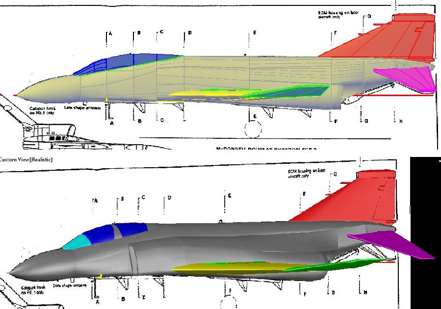
                       

Another Example was the humps on the wings to accommodate the landing gear, which I also struggled to get right.
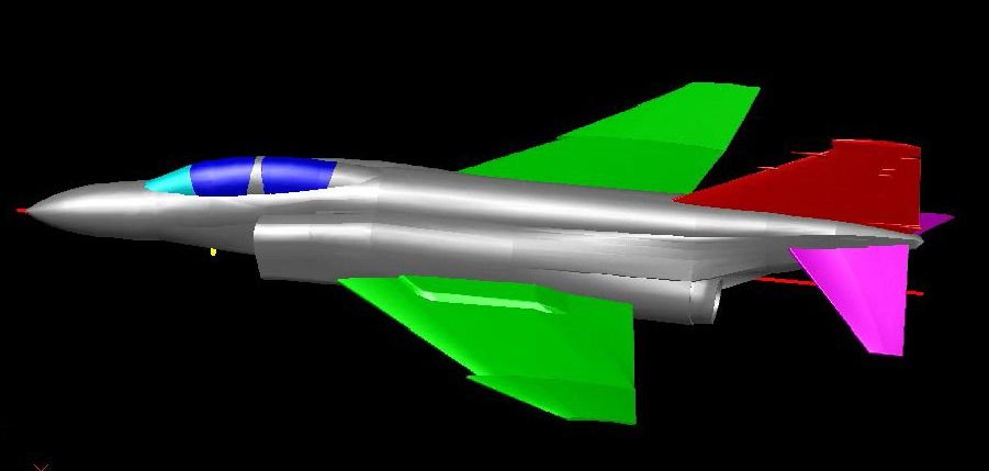
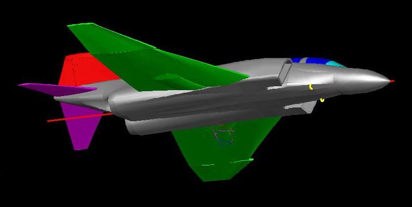


The next thing I did was add the air intakes on the nose and the engine intake ramps.  Note that I also did the detailing on the tail fin, adding the Pitot Mast, Stabilator “Feel” Pressure Inlet and Fuel Vent.  The rudder was “etched” by projecting a tracing of it on to the model, then drawing a 0.01” diameter circle on, and perpendicular to the line, and extruding the circle along the projected line, to create a 0.01” diameter solid “tube” on the surface of the model.  Subtracting this “tube” from the model leaves a 0.005” deep 0.01” wide half circle “etched” into the surface.
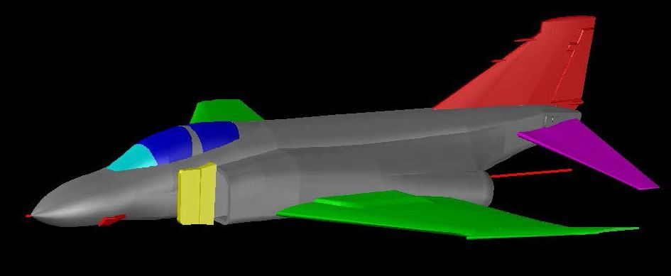
Using this method, I also detailed the wings.
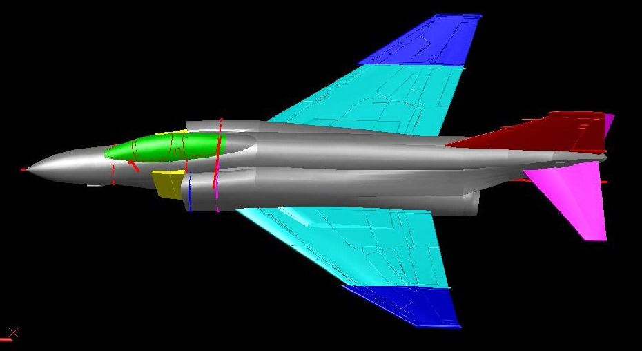
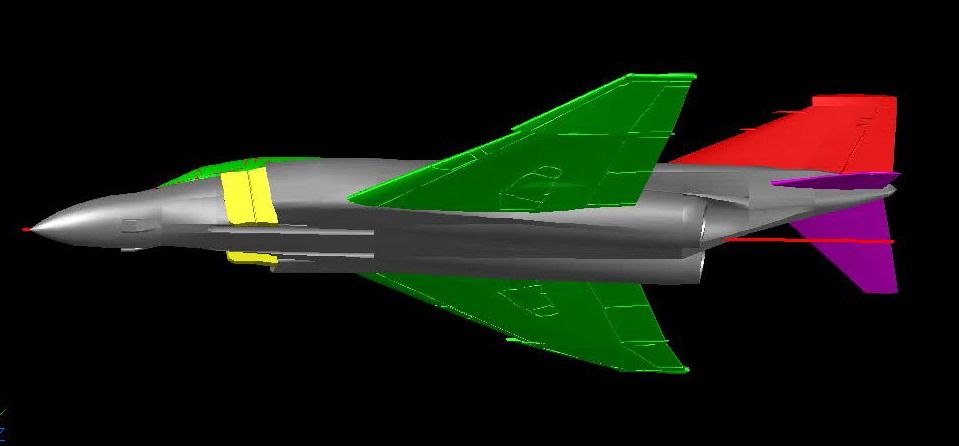


John and Ron have somewhat different modeling styles and thus have different ideas about what they like in a model kit.  I really enjoy making CAD models and since the differences are significant I decided to make two versions of the model, both with multiple options for display, but one with a detailed cockpit, multiple pieces for the canopy to allow the model to be displayed with the canopy open, separate wing tips for displaying up or down, and a few additional features, as will be seen later.

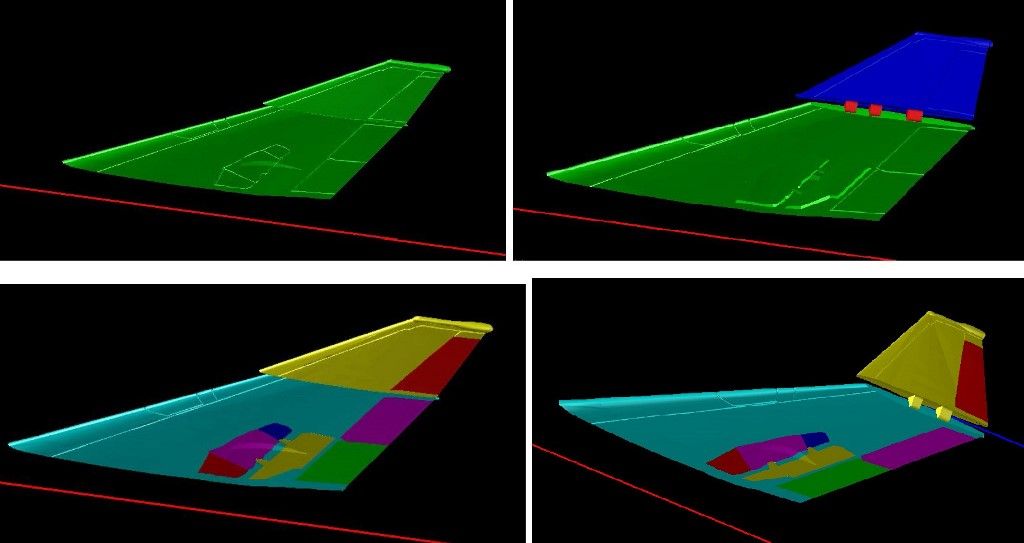
I started with the wing.  In the upper left image below, the wing is one piece.  It will be used on the “Basic” version.  The remaining images show the wing tip cut off and shown in both the folded up and down positions.  The lower two images show the additional parts, cut out of the wing that will be used in the “Deluxe” version.  I was advised later that the wing tip did not have a moveable surface so the red bit on the end was later rejoined to the wing tip.
 

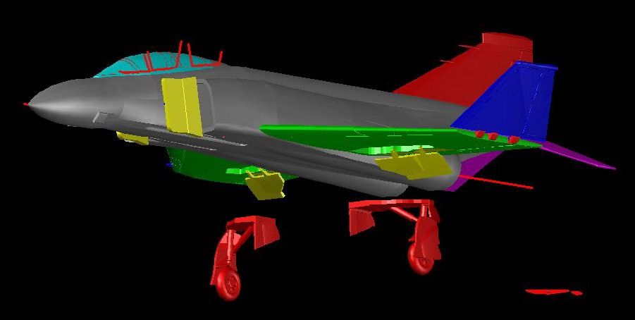
The next thing I did was make the forward landing gear.  Using the Grant Race plans and pictures, I made it using the parts I had cut out of the wing for the doors.  The image below shows the gear lowered from the notch it fits into on the underside of the wing.  Note also that the air brakes are shown in the down position.
 

After making the gear in the compressed position, I copied and modified it to make it extended as well.  Note the extended linkage in the extended position as compared to the compressed position.


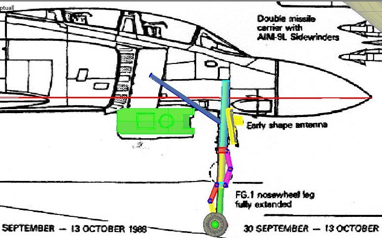
I did the nose gear next.  The image below shows how I used the plans to design the hyper-extended gear employed on the FG.1, using lofted circles and closed polylines.  You can also see how I used pieces cut out of the fuselage to make the doors.
 

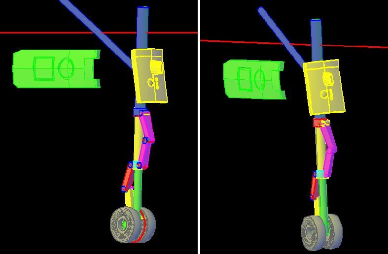
The image below shows the various components required to make the hyper-extended gear.  Obviously, it is a Work In Progress.
 CHEERS!!!

  • Member since
    March 2012
Posted by Rdutnell on Monday, May 26, 2014 12:12 PM

UPDATE 2

Continuing on…

The image below shows the three nose gear positions I made, Hyper-extended, extended and compressed.  The lower linkage is wrong as pointed out by Ron, but I forgot about it until he pointed it out again when the model was almost completed.  It should angle down and not protrude so far aft, but you get the picture.

The image below shows the completed compressed gear, exploded so you can see the parts.


The image below shows the relative positioning of the three different gear.  Note that the top and wheels are the same and that the modeler has the choice to show it being launched, coming in on final approach or on the deck.  A single piece door is also included if an in-flight display is preferred.


After completing the landing gear, I sliced off the nose to make the radome and also made the radar antenna.  Note the notches I included for positioning the radome if the modeler wants to display it closed. 


Next, I made the one piece cockpit for the Basic version. Recessing the glass areas required copying the canopy to the side, scaling it down, cutting out the glass areas in the original, copying the scaled down canopy back and then joining them.  The port on the radome was later removed, as John said it would be better handled with a decal.


To make the canopy pieces for the Deluxe version, I copied the canopy and sliced it along tracings from the plans.


The image below shows the canopies in the open position.


I then added detailing on the stabilators and added the winglets on the late model tail fin.


Next, I used the plans to make the tail hook, which will be attached to the airframe in the up position on the Basic version and included as a separate piece in the Deluxe version.

Next on the agenda, was detailing the fuselage.  The image below shows tracings of all of the panel lines from the plans…

…And the image below shows them after I projected them onto the surface.


I was about to begin the most tedious portion of making this model, but that’s for the next post.

CHEERS!!!

  • Member since
    March 2012
Posted by Rdutnell on Monday, May 26, 2014 8:20 PM

UPDATE 3

Hi Again All!

Before starting the “etching”, I decided to make the nose gear for the FGR.2, which did not have the extra link that the FG.1 did, but it was not hyper-extendable.  The compressed gear is shown at left in the image below, and both the compressed and extended gear are shown on the right.


To start the etching, I added the panel lines on the early (left) and late (right) versions of the tail fin.


I then did the nose section of the fuselage.   The images below show the “tubes” on the surface prior to subtracting them from the airframe.  The lower image shows it with the airframe layer turned off.


The image below shows it “etched” after I subtracted the tubes.


The following image shows the remaining surface tubes with the airframe layer turned off again.


The next image shows the port side after subtracting the tubes…


..And the image below shows the starboard side.


I then added detailing to the intake ramps, by recessing parts of them 0.004”


Then I copied the horizontal stabilators and cut notches in one set of them for use on the FG.1.  FGR.2 stabilators did not have slots, so these slotted stabilators are the second difference, after the hyper-extended nose gear between the two aircraft.


After this, I finalized etching the underside of the fuselage at the aft end.  I struggled with this part because I had a hard time finding good pictures of the area.


  • Member since
    March 2012
Posted by Rdutnell on Monday, May 26, 2014 9:40 PM

UPDATE 4

Continuing on, the next thing I did was round the aft end some more, add the tail light, modify the fuel vent…


…And added the auxiliary air vents on the topside.


After this I added the cockpit for the basic version, which consists only of seat backs and spheres for heads.  Note that I have also attached the wing tips on the basic version.


Next I made the auxiliary air vents on the underside…


…And made a 600 gal centerline fuel tank to test if the open vents would clear it, which they did. 


On the basic version these vents will be attached, as shown below.  On the Deluxe version parts will be provided to model them open or closed.


After that, I made the Skyflash (AIM-7) missiles.


Next, I made the inner pylons with AIM-9 launchers and AIM-9 missiles, which took a couple of tries.  Initially, I copied one from a previous model, but John didn’t think it looked right, saying that he thought the fins were too small.  I was sure they were right but used some plans I found on-line to redo it to confirm it.  The image below shows the plans I made the AIM-7s from.


The image below shows the AIM-7, and the upper left image shows the one made from the plans (blue) with the ones I copied from the other model.  You can see that John was spot on.  This was another instance of John’s feedback helping to make the model more accurate.  Thanks John!


I made BL755 Bomb clusters next…


…Followed by SNEB launchers, which I also made from plans I found on-line.


  • Member since
    March 2012
Posted by Rdutnell on Tuesday, May 27, 2014 10:26 AM

UPDATE 5

Good Morning Everybody!

I continued on the Phantom “build”, completing the SNEB pod clusters and adding 370 gal external wing tanks.


Following that, I did the SUU-23/A gun pod.  Once again, a search on line found plans that I used to make it.  Due to the small size, the gun barrels were made as one piece with the barrels being made by extruding 0.01” diameter circles on the surface of the center piece and joining them, so that half of the tubes protrude.  This will allow it to print and yet give the appearance of individual barrels.


The image below shows it with the AIM-7’s, SNEB pods and 370 gal outer wing tanks.


And here it is with the AIM-9’s.


The initial bomb and SNEB clusters were crudely done, and at some point I refined them to include TERs.  The images below show them as a work in progress.


The image below shows the TER with the SNEB pods, along with the SUU-23 and 370 gal outer wing tanks.


Next I made a couple of Dummy AIM-7’s.


At some time along the way, John pointed out that the AIM-9 launchers were not correct.  I had them at the bottom of the pylon, matching a kit part that I had, but unfortunately, the kit part was wrong.  So I redid it.


To Be Continued…

  • Member since
    March 2012
Posted by Rdutnell on Tuesday, May 27, 2014 12:42 PM

UPDATE 6

Hi Again Everybody!

The next feature I made was the in-flight refueling probe, which will be on the Deluxe version, but not on the Basic version.  I made it mostly using pictures and although it isn’t shown here, I also made a “plug” for those who do not wish to have it deployed.


Following that, I made the internal cockpit access ladder, which like the refueling probe will only be on the Deluxe version.  A plug was made for it as well.


Continuing with the ladder theme, I next made the external access ladder which was done entirely from pictures.  This too will only be included in the Deluxe version.


To this point the airframe had been a solid piece.  To lower the cost somewhat, I hollowed it out to reduce the volume of material used.  3D printing is cool, but it is still fairly expensive, which at the moment is its biggest drawback.  In any case, after I hollowed it out, I redid the tail pipe nozzles.  I did this for 2 reasons.  First, with the airframe hollowed out, I had to leave it open so that the support material used during the printing process could be melted out after printing.  Second, the original one was plain and needed some spiffing up.  Pictures sent by Ron and John were used to design them.  In the image below, you can see the new nozzles in position on the airframe…


…And in this image, you can see the connecting pins and holes I made for attaching them.


Sometime along the way, I copied the airframe to the side and created 2 new layers, “FG.1” and “FGR.2”.  I put one airframe on the FG.1 layer, and one on the FGR.2 layer.   I then moved the copied airframe back into position, turned the FGR.2 layer off, and modified the FG.1 airframe to include the catapult hooks, as shown below.


At this point the Basic versions of the FG.1 and FGR.2 were completed, so I arranged them and put the smaller items on frets.  This can be a timely process.  Laying the parts out in the most efficient manner can be challenging.  The image below shows the parts diagram and list of parts for the Phantom FG.Mk1 Basic version…


…And the image below shows the parts diagram and parts list for the Phantom FGR.Mk2 Basic version.  Note that they are very similar, which is no surprise.  The only differences are the catapult lugs on the FG.1 airframe, slotted stabilators (on the FG.1) versus un-slotted stabilators (on the FGR.2), and the nose gear.  Note that there is one less part on the FGR.2 because it does not have the hyper-extended gear.


  • Member since
    October 2005
  • From: New Port Richey
Posted by deattilio on Tuesday, May 27, 2014 1:48 PM

Bow Down Most impressive! I picked up the 1/350 AC-47 from Click2Detail and it truly is a little gem.
Any plans on tweaking these plans to produce an F-4C/D variant?


WIP:
Trying to get my hobby stuff sorted - just moved and still unpacking.


"Gator, Green Catskill....Charlie On Time"


  • Member since
    March 2012
Posted by Rdutnell on Tuesday, May 27, 2014 2:23 PM

Thanks Deattilio!  I'm glad you like it.


As for an F-4C/D variant, unfortunately I think that it would take a little more than a little tweaking.  I would likely have to completely redo most of it.  I won't rule it out, but if it may be some time before I get to it if I do.  I think my next venture is going to be a 1/350 scale U-2.

  • Member since
    March 2012
Posted by Rdutnell on Tuesday, May 27, 2014 5:15 PM

UPDATE 7

With the Basic version completed I turned my attention solely to the Deluxe version, starting with the cockpit.  After bouncing ideas on how best to do it off of Ron and John, Ron suggested that I make it so that it is installed from underneath.  Since this seemed like the best option of all of those that we discussed, I decided to try it that way.  The image below shows the cutout from the airframe that will become the bottom of the cockpit assembly.  The airframe layer is turned off in the image on the left, and on in the image on the right.  Note that because there are two separate airframes, I had to do the cutout step twice.

To position and size the seats I used a different set of plans with a cutaway view, as seen on the left below.  I copied these to the model reference frame, as seen in the image on the right. Note that I also extruded the top of the instrument panel from a tracing of its location on the plans.


Next I extruded a solid up using the cutout polyline to bring the deck up to match the seats, as shown below. 


The image below shows the cockpit assembly in progress.  The orange part on the bottom is the cutout and extrusion shown in previous images, and the base of the assembly.  The cayan part will eventually become part of the airframes, but they won’t be joined to them until much later.  The red bits on the sides, or parts of them, will become part of the assembly but are very rough at this point, as are the bulkheads and seats.


The image below shows it in this rough state with one of the airframe layers turned on


The images below show my first attempt at the seats.  The various components can be clearly seen.


The next two images show it a little further along.


At this point I started detailing the instrument panel.  Using pictures, I tried to capture the main features the best I could.  The image below shows it early in development.  The main limitation in the design is size.  In past models, I have limited my smallest sized objects to 0.008”, and it has printed nicely.  The smallest knobs here are 0.006” diameter, which I think will print, but am not certain.  Note that I have also drawn the rudder pedals and the first draft stick.


The image below shows the layout for the starboard side control panel. It also shows the window latch handle.


The image below shows the completed IP and starboard side panel.  Note that I also redid the stick.

  • Member since
    March 2012
Posted by Rdutnell on Tuesday, May 27, 2014 9:23 PM

UPDATE 8

Hi guys!  The journey continues.

The image below shows the detailing started on the rear instrument panel.  Note also that the radar homing and warning device protruded into the canopy windscreen as initially designed.


To fix this, I shave off some of the material on the inside of the aft edge of the windscreen.  I hope it’s not too thin.


The image below shows the completed rear IP. 


Here’s a view of the entire assembly at this point.  The two canopy latch handles in red will be attached to the airframes, and the magenta bit in the center will be attached to the canopy center post.


Next I did the rear left panel as seen below.  I just perhaps point out that much of the detailing of the panels was adlibbed although I tried to match the few pictures I could find as closely as possible.  The rear left panel is adlibbed more than the others due to the fact that I never found a really good picture of it.


The image below shows the rear right side, which doesn’t really have a panel.


With the cockpit detailing completed, I joined the mid-section to both airframes (copying it to the side, doing one of them, then moving it back and doing the other).   The images below show one of the resulting airframes.


The images below show the completed cockpit assembly.


I mentioned in a previous post that the nose gear for the FG.1 wasn’t right.   The image below shows the final compressed FG.1 nose gear…


…And this image shows it hyper-extended.  Note that the lower link slopes down instead of being level, like I originally had it.


With the models completed, I arranged the parts, as before with the basic models, and made frets for the smaller parts.  I didn’t have to totally redo it though as I could use some of the parts from the basic model.  Here is the parts diagram and parts list for the FG.1 Deluxe version.


And here it is for the FGR.2.


I have exported all of the files for the 4 models to STL format, repaired those that needed repairing, and uploaded them to C2D.  They should be available soon.

CHEERS!!!

  • Member since
    November 2016
Posted by sengo on Thursday, November 17, 2016 1:12 PM
Hello Russ, I'm new to this forum and wonder if you can assist me. I am trying to locate front, and rear cockpit ladder drawings for a FG.1 RAF Phantom. The Ulster Aviation Society would like to have a go at manufacturing a set for its aircraft. Best regards Leonard
  • Member since
    March 2012
Posted by Rdutnell on Friday, November 18, 2016 8:14 AM

Sorry Leonard. I cannot.

JOIN OUR COMMUNITY!

Our community is FREE to join. To participate you must either login or register for an account.

SEARCH FORUMS
FREE NEWSLETTER
By signing up you may also receive reader surveys and occasional special offers. We do not sell, rent or trade our email lists. View our Privacy Policy.