UPDATE 1
Good Morning Everybody!
One thing I have learned about modeling, be it in wood, plastic, or virtual space, is that it is easy to look right at something and not see it. More than once in the making of this model, Ron and John had to point out something that I either missed, or didn’t get right. The radome/fuselage interface was one of these, and it took me several tries to get it so that it passed the sharp eye of John.
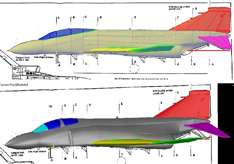
Another Example was the humps on the wings to accommodate the landing gear, which I also struggled to get right.
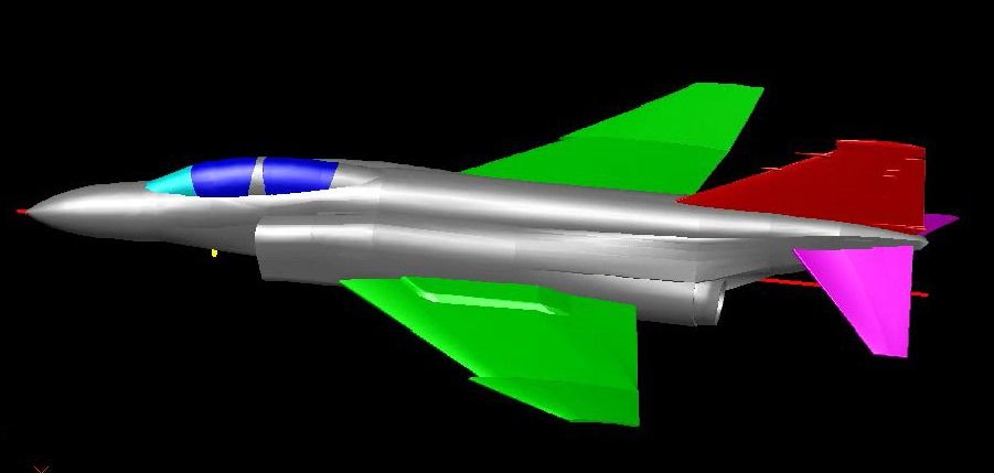
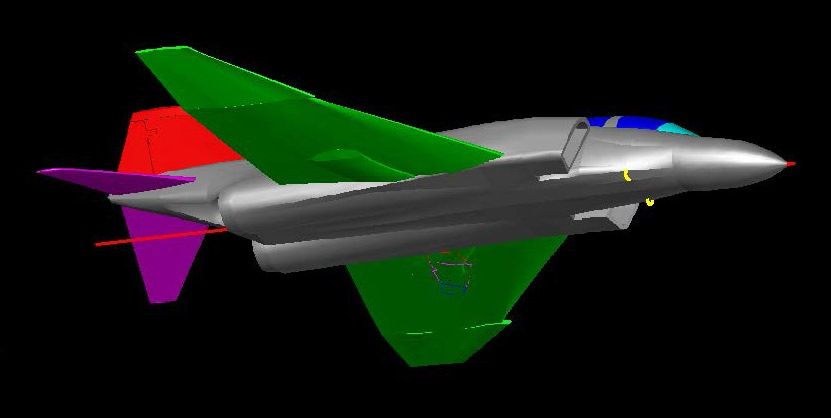
The next thing I did was add the air intakes on the nose and the engine intake ramps. Note that I also did the detailing on the tail fin, adding the Pitot Mast, Stabilator “Feel” Pressure Inlet and Fuel Vent. The rudder was “etched” by projecting a tracing of it on to the model, then drawing a 0.01” diameter circle on, and perpendicular to the line, and extruding the circle along the projected line, to create a 0.01” diameter solid “tube” on the surface of the model. Subtracting this “tube” from the model leaves a 0.005” deep 0.01” wide half circle “etched” into the surface.
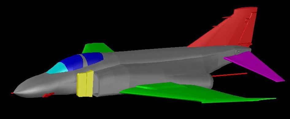
Using this method, I also detailed the wings.
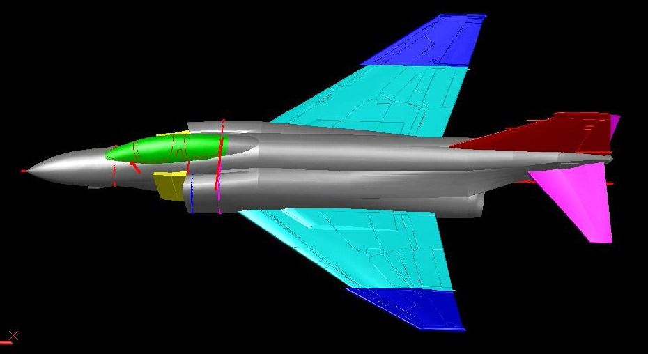
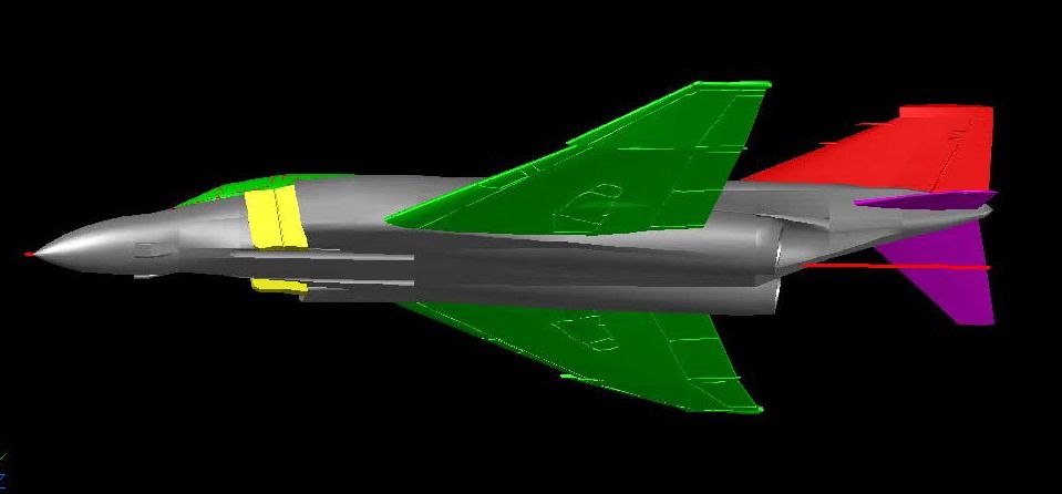
John and Ron have somewhat different modeling styles and thus have different ideas about what they like in a model kit. I really enjoy making CAD models and since the differences are significant I decided to make two versions of the model, both with multiple options for display, but one with a detailed cockpit, multiple pieces for the canopy to allow the model to be displayed with the canopy open, separate wing tips for displaying up or down, and a few additional features, as will be seen later.
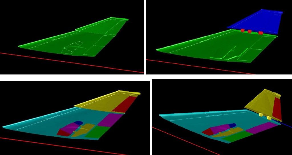
I started with the wing. In the upper left image below, the wing is one piece. It will be used on the “Basic” version. The remaining images show the wing tip cut off and shown in both the folded up and down positions. The lower two images show the additional parts, cut out of the wing that will be used in the “Deluxe” version. I was advised later that the wing tip did not have a moveable surface so the red bit on the end was later rejoined to the wing tip.
The next thing I did was make the forward landing gear. Using the Grant Race plans and pictures, I made it using the parts I had cut out of the wing for the doors. The image below shows the gear lowered from the notch it fits into on the underside of the wing. Note also that the air brakes are shown in the down position.
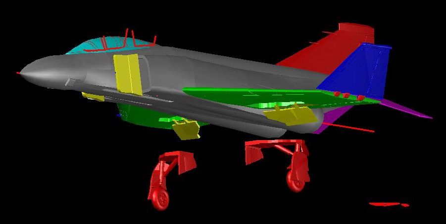
After making the gear in the compressed position, I copied and modified it to make it extended as well. Note the extended linkage in the extended position as compared to the compressed position.

I did the nose gear next. The image below shows how I used the plans to design the hyper-extended gear employed on the FG.1, using lofted circles and closed polylines. You can also see how I used pieces cut out of the fuselage to make the doors.
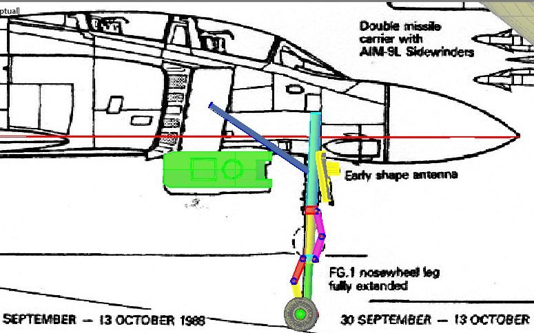
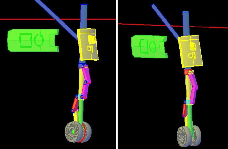
The image below shows the various components required to make the hyper-extended gear. Obviously, it is a Work In Progress.
CHEERS!!!