SEARCH FINESCALE.COM

Enter keywords or a search phrase below:

Tamiya 1:32 F4U1-A1 Corsair Build Thread

10101 views
75 replies
1 rating 2 rating 3 rating 4 rating 5 rating
  • Member since
    December 2010
  • From: Salem, Oregon
Posted by 1943Mike on Wednesday, November 7, 2018 10:47 PM

As I would expect, but am continually impressed by, your work is exceptional.

And, since it's a corsair F4U, I'll be following along looking at your amazing building prowess and enjoying every moment.

Mike

"Le temps est un grand maître, mais malheureusement, il tue tous ses élèves."

Hector Berlioz

  • Member since
    November 2004
Posted by snapdragonxxx on Thursday, November 8, 2018 4:50 AM

Wow! That engine is superb and you have shown me a new way of doing the ignition harness which I had not considered before.

I just wish you could also include metric measurements as well !! :)

I have Zoukei-Muras Shinden in 1/32 ready to start and their new 1/32 Ki-45 booked to collect at the IPMS Telford Show on Saturday.

After seeing your wire work I am going to have to up my game and the Shinden will be an excellent learning opportunity.

Thanks for showing the technique


James

  • Member since
    July 2016
  • From: NYC
Posted by Johnny1000 on Thursday, November 8, 2018 5:42 PM

That engine is looking good, especially around the cylinders. Are you planning on detail painting the reduction box? 

  • Member since
    March 2012
  • From: Louisville, KY
Posted by Builder 2010 on Thursday, November 8, 2018 7:13 PM

Well.. thank you! 1:32 compels you to do more. I did the same level of nonesense in my 1:48 B-17 which had Eduard upgrades on all four radials. That was nuts! In 1:32 you at least have a fighting chance, but you're still drilling really small holes in really thin pieces of styrene. It's not for the faint hearted.

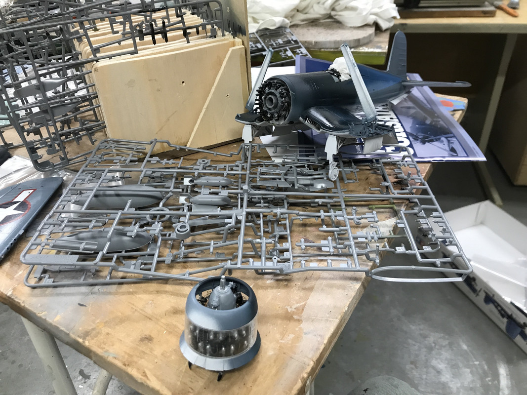
Got in the shop late today but got that last ignition lead installed, touch up painted the whole deal and added the last parts. The engine is complete and ready to go into the air frame. On the Trumpeter Avenger, not only was the engine detailed, but they included all the behing-the-firewall gear case stuff and engine mounts. These were then buried behind the skin. In order to show it all off I had to cut open the skin complicating the build considerably.

For some reason, the distributors didn't fit over the ignition ring properly and I had to doctor them a bit some they nestled in. I also added the magneto, the prop governor and the little part at the bottom which has something to with the oil sump.

These parts were supposed to be light gray, but I left the distributors semi-gloss black as I've seen in my pictures. Theoretically, there is some wiring that goes to an from the magneto, but enough it enough. This engine is done. 

I painted the valve bodies Tamiya chrome silver, and touched up the rest. Interesting about Tamiya paint... unlike normal acrylics, which when dry can really be reconstituted, Tamiya when dry can be sort of brought back to life with isopropyl alcohol. It's not perfect, but it let me re-use a little bit of the light gray I mixed that had totally dried in the little epoxy cup I used as my mixing bowl. I was able to use it to touch up the gear case and paint the few added pieces.

And lastly, I stuck the engine onto the airframe to see how it looks. There are some cowl pieces that need to go on before gluing it in place, and these parts have to be painted dark gray in their interiors (although I have no idea why since they won't be seen). I am contemplating either using a clear cowl piece to show off the hardware, or put one of the pieces in an open/upward position to do the same thing. There are some of the front bank exhaust pipes that are not aligning perfectly with the pipe extension leading to the outlet.

Hard to believe that a power package that little put out 2,000 hp or more. By the end of the era for the 2,800, they were getting 2,800 hp out of it. That's 1 hp per cubic inch. Now to put that in perspective, top fuel dragsters are now getting almost 10,000 hp out of a basically 400 cu. in. engine, but they last for about 1 minute of running time. The 2,800 was running thousands of hours putting out that energy. If you don't want something to last more than a few minutes, you can get a heck of lot of HP out it.

Once the cowl pieces are fit, I'll be moving on to the flight control surfaces.

  • Member since
    November 2004
Posted by snapdragonxxx on Friday, November 9, 2018 4:35 AM

I would use the clear cowl but paint the right hand side, leaving the left side clear. This way you can have a full paint job on the right side and still see the engine on the left.

it does take some careful masking and painting but with that engine, well worth the effort.


James

  • Member since
    March 2012
  • From: Louisville, KY
Posted by Builder 2010 on Friday, November 9, 2018 7:24 PM

The cowls are split top and bottom, so I'll leave the top clear and the bottom painted. The clear parts have a slightly frosted texture which tamiya has included on all the skin parts to give it a better paint adhesion. They recommended and I did dip the clear parts in Pledge and will check them out on Monday after they completely cure.

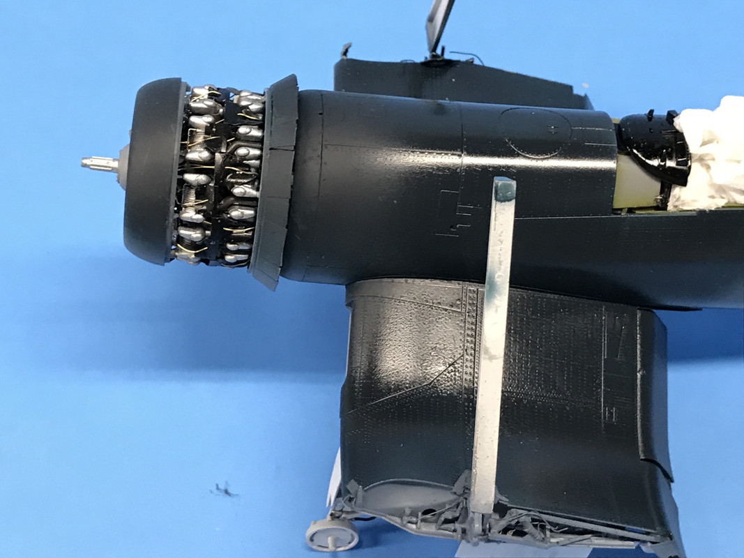
After studying more images of the R-2800 I noticed two other prominent pipes that could easily be inculded since they're right in the front bottom of the engine and could be seen through the wide open cowl. These are oil scavenge lines that lead from the oil scavenge pump that sits at the bottom of the gear case and goes to the oil receiver at the bottom onf the front cylinder bank and the other goes back through the engine and ends up probably at the imaginary oil tank. The smaller lines is copper colored phosphor bronze and the larger a piece of 0.032" brass, both of which were made chrome by the Molotow Chrome pen. Now the engine's done! Whoops I just noticed that I didn't put on the PE builder's plate. I can do that through the open cowl.

With the engine complete it was time to install the forward cowl leading edge and the open cowl flap ring. You can have it will the cowl flaps open or closed. I chose open since it shows off more of the exhaust spaghetti. As usual the engineering was excellent in locating the cowls to the engine, but becuase I had painted the lugs that tie the valve covers on selected cylinders to the rings. So the glue was having trouble getting a good grip. I ended up helping it along with CA.

The remaining two exhaust collectors were put in place and then the entire engine was joined to the fuselage by using tube cement just on the center ring which has the heft to provide a good joint. The cowls varied depending on whether you're doing version A, B or C. The "Big Dog's" Corsair was the earlier B version. This plane had opening cowl flaps at the 11 to 1 o'clock posirtions. These were eventually closed off permanently when the airplane had the habit of fouling the windsceen with leakage from the engine. The B model also had the original shorter tailwheel. It was raised in subsequent models to give the pilot of better view forward over the huge nose for carrier use. The long nose was the reuslt of having the fuel tank in front of the cockpit. A couple of tiny PE pieces help hold in the opened top flaps.

I liked how the new exhaust pipes nested into the others that were already in place.

This was set aside to dry. While the cowls were setting up, I started on the horizontal stabilizer. Both stabs are the same. It was clear that Vought chose to do this to simplify construction. One side has a series of circular access panels. So one the right side they're on top, and the left they're on the bottom. The trim tabs separate parts as is the linkage that operates them. You can have the elevators in neutral or dropped position using a different hinge part. I chose to have them dropped. Another B option is filling the holes in the tail. In the later models this was faired over with a rounded cover.

When I glued the horizontal stabs in place, again I marveled at the fit. No filler needed. I used tube cement here to give a little more coverage and dwell time. I just put it on the middle of the mounting stub and let the stab push it further towards the junction.

Next up was the tailstrut and wheel. It's a lovely affair with lots of parts, great detail and good engineering. In retrospect, I probably shouldn't have glued it in yet since it complicates masking the interior from the white bottom color, BUT... it is held in tightly held by a sandwhich with part M2 that's also a body part. I could have put that part in without glue, painted the bottom, removed it and then glued in the tail gear. But that plane has left the runway and the tail gear is glued in.

I airbrushed flat white, painted the hydralic ram with the Chrome pen and then installed it, and glued in place M2. That ring just behind the wheel caster hole is the attachment point for the catapult. It's a tail dragger so I guess they have to link up at the back. The diagonal link ending at the tail is the arresting hook operating lever.

I ended the day putting on the tail wheel doors. These too have two version depending on whether you're using the short of long tail wheel. So much of this model is detailed in plastic that you'd have to do with after market or scratch build. I will, however upgrade the wing fold area since I found some good reference materials for some added piping.

Work begins again on Monday. Have a great weekend.


  • Member since
    February 2012
  • From: Olmsted Township, Ohio
Posted by lawdog114 on Saturday, November 10, 2018 2:35 AM
Nice attention to detail. That 2800 is beautiful..

 "Can you fly this plane and land it?...Surely you can't be serious....I am serious, and don't call me Shirley"


  • Member since
    November 2004
Posted by snapdragonxxx on Sunday, November 11, 2018 4:11 AM

Stunning engine! I would add the manufacturers plate now while you have complete access.


Zoukei-Muras' latest release is at this moment in my grubby little paws with the official release being December/January.

They've done it again and you should get one!

  • Member since
    May 2013
  • From: Indiana, USA
Posted by Greg on Sunday, November 11, 2018 12:46 PM

Everyone is right, that engine is spectacular. Yes

  • Member since
    March 2012
  • From: Louisville, KY
Posted by Builder 2010 on Monday, November 12, 2018 6:37 PM

Thanks guys! This is my third aircraft with radials. The first was the Yankee Lady that started with a Revell/Monogram 1:48 B-17 (old, awful kit) but had Eduard engine kits that were tiny, but very fine.

Then came the Avenger... a Trumpeter 1:32 with an R-2600 radial that had added stuff like this one including the Eduard PE engine set. Came out okay.

But practice makes perfect so the third one, so far, is the best. I didn't put that plate on today and I need to make a note to myself to do it. The cowl is very open and you see a lot of the engine so I can get to it. 

Today was mostly a painting day. It started with the wing center section bottom which has white, Interior Green and Intermediate Blue painting. I painted the white first and then masked and painted the interior green, all by the detail airbrush. I find I'm using this gun more and more since the spray pattern is so nice that I can hold parts in my hand while painting without covering myself.

A neat little assembly which will add a lot of hidden interest to the model is the oil cooler/intercooler intake trunk. It was a prominent feature of the early Corsairs. Later models had some of these intakes in the cowl lip.

Each side consists of 8 parts: 5 injection molded and 3 PE. One of the PE pieces will not be seen when the wing is assembled. This is the inlet facing side that will be seen in the wing opening.

This is the outlet side facing into the fuselage and shows that soon-to-be-hidden PE grill.

Lastly, I put together the main wing spar in the wing-folded position. Again it has multiple colors including the wing hinge area in the intermediate blue color.

It took me almost a 1/2 hour to try and match that intermediate blue color. Tamiya calls out A-20, an aerosol pre-mixed color. I don't want to use rattle can paint in the house for areas as big as the plane so I bought some Tamiya bottle paint to try and get a match. The medium blue I bought which I thought would work as a starting point didn't work. I then tried to lighten the Royal Blue, but that didn't work either. I then mixed up some Flat Blue and lots of white (white was used in all the other mixes too), and was getting closer. I was matching this all to the color sheet included in the model. I found that I needed to add a small amount of red since the color was tending to a blue green. Here's the output from all those tests and the one that I thought was the closest as designated by the arrow. I can probably get it a bit closer and then I'll need to scale it up to make a batch for the airbrush. Or... I might buy some Vallejo that's already matched to this scheme. I'm not a big Vallejo fan since it's more temperamental, doesn't thin with IPA and dries much slower.

Tomorrow I have some errands to run and won't get so much done, but I will be continuing with building the wing center section.

  • Member since
    March 2012
  • From: Louisville, KY
Posted by Builder 2010 on Tuesday, November 13, 2018 5:06 PM

Ended up ordering Life Color Non Spec Sea Blue and Non Spec Intermediate Blue to solve the paint color dilemma. I also got the word from one of my other threads that mixing Tamiya XF-18 (5 parts) and XF-2 (4) gives the intermediate blue. I'll give that a try too and see which one works best. When I was mixing the white and blue and did notice it seemed to have a bit of green and I countered that with a tiny bit of red.

  • Member since
    November 2004
Posted by snapdragonxxx on Tuesday, November 13, 2018 5:31 PM

I would have personally gone with Vallejo 71.295 for the NS Sea Blue (ANA 607) and 71.299 (ANA 608) for the Internediate Blue with 71.279 (ANA 601) for the Insignia White.

I can spray them through my 0.2mm H&S Evolution without thinning and they cure quite quickly although I am not a fast builder and do let stuff cure overnight. I like that they are chipset accurate and not the PC Scale conversion stuff which with some paints are not even close to the correct colour. They have a strong pigment and coverage is fantastic.

I do use other paint ranges depending on my colour needs and my favorite metals are AK's Xtreme Metal and Vallejo's Metal colour.

Did the Royal Navy's Fleet Air Arm (FAA) fly Corsairs? would be nice to do one of those in FAA colours!

  • Member since
    March 2012
  • From: Louisville, KY
Posted by Builder 2010 on Wednesday, November 14, 2018 6:28 PM

I don't know the answer to your question. Regarding Vallejo: Scale Reproductions has a full supply of their colors, but we couldn't find the ones that we thought were a good match. I'll use your spec numbers and try again.

Building in the inner details of the wings is a lot of fun. First I did some dirtying up of the oil cooler intakes. I again used the Tamiya Black Panel Line wash. 

That dirty front lip is hidden behind the fairing that goes on when the wing halves have been brought together.

I glued in the main spar and all the bulkheads and almost screwing it up by gluing the wing bulkhead in before the spar. It goes on top of the spar and interlocks with it. Luckily, the glue hadn't set and I was able to disassemble the errantly glued part and get it right. I then painted all the wheel well interior parts white. I then masked the white and sprayed the interior green on some parts that will never be seen. I didn't spray the exterior wing joint since this is going to be intermediate blue.

Here's the reverse view. There are a suprisingly high number of parts in this sub-assembly.

The wheel well ceilings were painted off the model so I could air brush the interior walls from both directions. I then glued the ceilings into place. Here's the wheel well fully painted before any weathering. The overspray doesn't matter since this section ends up being white.

While there's a ton of detail in the wheel area, what's missing is all the hydraulics. After gluing in the control valve for the wheel door cylinders. The valve and cylinders are there, but no inconnecting piping. So... what to do? The problem is that the valves are glued in place and not easily accessible. I didn't even realize what the valve was when I glue it in place according to the instructions.

I can't get the micro-drills in at that angle. I may be able to get the micro-tubing over top of the those little fitting and put the tubing into the tubes. You can't see these details unless the model is picked up, and I don't want people doing that.

Here's an example of the piping that's missing.


I know I'm going to add some 3D piping to the wing fold area since it is so obvious. Whether I'm going to do it in the wheel well remains to be seen. The detail is all on the back of the main spar and won't be seen looking from the front. I'll take input from all of you to help me decide.

  • Member since
    November 2004
Posted by snapdragonxxx on Thursday, November 15, 2018 11:27 AM

If you have trouble getting the vallejo model air colours, then let me know and I will send you their US Navy & USMC colours 1940-45 air war set.


https://acrylicosvallejo.com/en/producto/hobby/sets/air-war-en/us-navy-umsc-colors-wwii-1940-1945-71157-es/


This build looks good and I just had to start on ZM's Ki-45. Look for a thread coming soon!

  • Member since
    March 2012
  • From: Louisville, KY
Posted by Builder 2010 on Thursday, November 15, 2018 6:36 PM

I appreciate the offer. I should be getting the word tomorrow if the Life Color paints are in. I'll check the hobby shop out for those Vallejo colors. If the Life Colors are way off, I may take you up on your offer.

Today's output was a mixed bag. I got the upper center wing skins fitted out and joined to the lower skin. Got the lower skin bottom all fitted out with a couple of hiccups. Then I decided, fatefully, to start working on piping all the wheel well hydraulics. And just at the end of the day, when putting too much stress on the wing trying to get the last stubborn brass fitting on the gear door valve, I broke off the folded wing spar. And this is not going to be an easy fix.

So let's begin at the beginning.

On the bottom of the upper wing skin there are three parts on each side: the intercooler face at the wing root, the ceiling of the forward wheel well and the reverse curved fairing that contains the flaps. You have to constantly pay attention to whether you're building a "flaps up" or "Flaps down" version since there are different fairing parts in the flap area. I'm building "flaps down".

Here's a CU of the intercooler. and the duct leading to the carburetor. 

The intercooler was supposed to be Tamiya Metallic Gray so I mixed up some Life Color dark sea gray and Tamiya chrome silver. And of course, none of this is even remotely visible in the finished model.

The top wing was joined to the bottom and, of course, it fit like a glove.

The leading edge fairings for the cooler inlets went on nicely and the innards look pretty good. If you were able to peer through the louvers, which you can't really do very well, you would be able to see the intercooler facing. But I know it's there.

On the wing bottom there were several little bits and pieces. In the center is a vented hatch which is purposefully held in a slightly open position. Next to it are two reward facing hooks, the purpose of which I have no idea, possibly catapult use... I got one glued in and the other when manipulating it took off and supposedly disappeared. I thought about scratch-building another, but it was a bit delicate and didn't look too promising. So I got the next tiny part, the fairings that will over so actuator or another. I got one glued in and was gluing the other side in, and noticed the first piece, which I thought had set enough, had disappeared. And it was really gone. This piece was a little more straight forward so I did scratch-build another out of a piece of sprue. 

Then I found the missing hook. I put it on and added the outlet fairings from the oil cooler housing. Lastly, there was a triangular brace in the opening where a bottom window is placed which I glued in and then glued in the bottom window. The kit has masks, although they are not die cut and you have to cut them yourself. They're made from the material that Tamiya uses for their wonderful masking tape and it's slightly deformable. All of this gets painted Insignia White.

The above also shows more fairings for the "Down-position" for the flaps.

This brings me to the wheel well piping. I found that one of my Albion fine brass tubes is has the right O.D. for my finest gauge of solder. And this same tube kind of fits onto the nubs representing pipe fittings on the valve, except for the top position. I had to cut this off so the tubing will fit on the narrower stem. 

I got 11 out of 12 fitting in place and was fussing with the last one. It was one that would go over the top stub which was just a bit oversized and I was pushing a bit too hard and didn't realize what else I was putting pressure on. It was the folded outer wing spar. And this is a bad place for a break. There's very little surface area for gluing, and similarly, there's not much material to drill and pin. My first attempt to pin the hydraulic actuating arm and got it pinned, but then it broke below the metal reinforcement. I then drilled the main part for a pin, but it's a bit misaligned. 

This is getting messy and I'm contemplating what it would take to rebuild the joint entirely in brass. There's also another possibility which is to have one wing up and one wing down. That's not a terrible thought and I have entertained it before. If I don't make the entire thing out of brass, I could make that actuating arm out of brass and marry it to the plastic parts. All of the lugs and fitting could be brass since I've been doing stuff like this fairly recently. In fact, if done correctly, you could almost make the wing fold functional. Stay tuned...

  • Member since
    November 2004
Posted by snapdragonxxx on Friday, November 16, 2018 5:09 AM

Sorry to hear about your mishap but a working hinge out of brass? I would want those to add to the kit so maybe you have accidentally found a sideline?

In regarding the paints, You should be able to get the colours you need as singles and if your supplier stocks the full model air range you should be able to get the colours no problem with the 71 numbers I gave you and before putting on the model, sacrifice some white plastic spoons to the great paint God and do a test between the lifecolor and the Vallejo and I bet there is a noticeable shade difference, with Vallejo being the chipset accurate one.

To me, watching this is a learning experience for when I do the kit and I will do my normal look at what can be added and how I can alter the build to accomplish this without causing problems and breakages.

Although Tamiya provide a masking set that you have to cut out yourself, I think that investing in a set from Eduard could be a good thing using the Tamiya ones as backup.

I would like to know your overall impression of the kit.


James

  • Member since
    March 2012
  • From: Louisville, KY
Posted by Builder 2010 on Friday, November 16, 2018 8:40 PM

My overall impression of the kit is SPECTACULER. I've been building models since I was 8 with a few years off for driving, girls and guitars, and this is the best engineered model I've ever built. If something doesn't go together perfectly, you're putting it together wrongly. 

The first thing I did today was photograph the hinges from both sides, import it into CorelDraw and draw the 1:1 scale parts for the hinge directly over the scaled pictures. 

The parts are very small, so before getting into a jewelry project I decided to see if I could get the plastic parts together using metal pins of varying sizes. For the main joint I used 0.022" phosphor bronze, and for the fold actuating strut I used a piece of 0.010" guitar E string. I'm pretty good at drilling tiny holes in the middle of tiny rods. I use a very sharp dividers pin to make a mark in the center of the part and then drill it with the carbide drills. This time, I just spun the drill back and forth in my finger tips instead of putting it in a pin vise. I found I could control it better and not put too much stress to break the drills.

This actually held pretty good. The junction is pretty munged up with CA, but the intermediate blue will hide some of it. 

With the hinge fixed, I got back to putting in the wheel well piping. I got that last ferrule into place and then, using thin solder (about 0.022), I put the 6 lines to the control valve. The two center lines come and go to other parts of the airplane so I drilled holes in the wheel well sides and fed them through. The top and bottom lines on both sides go to the tops and bottoms of the door operating cylinders. These are put onto the doors first before you glue the doors on so the piping can't be completed until doors are in. I'm not so sure how well this is going to work and I'm going to see if the cylinders can be installed before the doors so I can paint the entire bottom before the doors go one.

There are number of other electrical wires that pass through the wells, but I'm not sure I'm going to install them. That being said, the main gear actuating cylinder will have lines going to it.

Next up was the wing fold detailing. It's a very complete model just with the plastic. I sort of painted myself in the corner by putting in some oversize fittings that impeded putting in the parts that came later. It's hard to figure out where these pipes should go before the rest of the parts are in place, and then it's too difficult to put them in so you have to get a head start.

For the fold area, I did smarten up a bit. I put the piping on the fittings BEFORE gluing them into the wing. And I held the wing with a quick clamp that was in turn held in my Panavise which kept my clumsy hands away from those delicate wing spars so I wouldn't break them again.

It was those two fittings that got in the way. This is a critical part in the airplane. It's the hydraulic cylinder that moves the pin into the wing lock that prevents the wing from folding up again when the plane's in the air. It has a line on both ends since it's a double-acting ram.

Another hydraulic cylinder that goes in is the flap actuator. I broke off the piston rod on this one so I made another with a piece of 0.022" phosphor bronze. I flatened the end and then bent it so it would wrap around the little pivot.

Here's all the hardware set into the fixed wing portion of the wing fold. There's also a valve body that goes into the folded wing area and piping associated with it. It's basically a swivel that permits the hydraulic lines to pivot around the wing-fold hinge line to get the fluids to the ailerons which are also hydraulically assisted.

You can see the fitting mashed over the side with the addition of the flap actuating lever.

The next milestone step was the joining of the wing to the fuselage. Like other steps, this one went together very well. I put the thin cement on the outside of the joints and just let it wick in. Any surface inperfections that this causes will be hidden by the paint.

I'll have one more work day on Monday to start work on main landing gear and then we'll be off to our son's house for Thanksgiving. 

  • Member since
    November 2004
Posted by snapdragonxxx on Saturday, November 17, 2018 4:38 AM

Nice save with the hinge.

It would be nice to be able to have working hinges, but although 1/32 is large scale some things are just a bit too much and I do applaud you for taking a look at that opportunity. Maybe if Airfix put out a 1/24 kit then a working hinge might be included in the kit, or it would be easier to produce one in that scale.

I would love to see what you could do with Airfix's new 1/24 Hellcat released next year. It is already on my list.


Have a nice Thanksgiving.


James

  • Member since
    March 2012
  • From: Louisville, KY
Posted by Builder 2010 on Saturday, November 17, 2018 12:58 PM

The problem is that styrene is just not sturdy enough in the thin cross section that the scale hinge is. It could be out of an engineering plastic like Delrin which is used from model train couplers and is very tough. Even ABS is better than pure styrene. I may try and build the brass hinge just for fun. If it could be a lost wax casting, now that would be something. My guess is the real hinge is a steel or aluminum forging. Cast metal wouldn't cut it.

  • Member since
    March 2012
  • From: Louisville, KY
Posted by Builder 2010 on Monday, November 19, 2018 5:55 PM

Happy Monday! Unlike most mortals, I like Mondays as much if not more than weekends. That's because of my deal with my wife where I do nothing in the basement on weekends. So Mondays are when I can build models and that's fun for me. More fun than watching college football of schools of which I care not.

Picked up the Life Color Sea Blue and Intermediate Blue for the Corsair. And while I was there I was given a present; another Tamiya Corsair. This one was a "Bird Cage" version that was produced by Tamiya a bit earlier. It was not complete and was from an estate. Missing was the cockpit, the lower wing details, and most importantly, the engine. I would have loved to have built another engine to display along side. I did, however, get the wing fold parts (a dollar short and a day late) and the landing gear parts, of which I did use one this afternoon.

My session today was spent assembling those very intricate main landing gear. Many parts are included and there's a steel shaft that is glued into the two halves of the main strut. This stiffens the assembly nicely and I'm sure that it will support the plane as it should. Being a tail-dragger, no nose weight is needed to have it sit correctly. I drilled the jack cylinder to prepare it to receive the hydraulic lines. Which, BTW, I find that it looks like the middle line from the valve didn't go through the wing bulkhead. Instead, it goes through the main spar and enters the gear chamber. This tells me that it's the one that operates the jack. So I prepared the valve by attempting to pull the solder pipe out of the wing bulkhead and re-route it through a hole in the main spar that I drilled. But the line was too short! So I tried to pull the line out of the brass ferrule, but the middle and bottom ferrules broke free of the valve body. So now I'm in the middle of reattaching everything... and then I ran out of time.

The gear will be painted off the model since there's a decal that goes on the strut that will be easier to apply when they're separate. There's very little of the oleo piston showing so using the Chrome Pen or Bare Metal Foil is going to be very challenging. You don't have to rig a break line on this model. It's nicely molded by Tamiya.

We're heading to PA for Thanksgiving so I'll see y'all on the Monday after the holiday. Everyone have a pleasant, happy, satisfying and very safe Thanksgiving!!

ZAT
  • Member since
    November 2018
Posted by ZAT on Tuesday, November 20, 2018 11:56 PM
WOW!!! That is some amazing work. The 1:32 F4U is on my list to do, now that I've picked up another hobby. I'll have to get a few smaller scale builds completed to master some new skills...
  • Member since
    December 2013
  • From: Greenville, TX.
Posted by Raymond G on Thursday, November 22, 2018 12:10 AM
I'm just catching up on this build, and all I can say is wow! I'm impressed with both the kit and your skill. I really like the work you put into the engine. The F4U is probably my favorite bird. Days of watching Baa Baa Black Sheep as a kid and as a member of the Civil Air Patrol in the 80's my squadron was TX-214. So, naturally the squadron name was the Black Sheep, the only one endorsed by Pappy himself, by the way. My first "big boy" build, was Tamiya's 1:48 scale of the A model. I was impressed by its detail. I am really impressed by the 1:32. I guess I'm going to add this one to my list. Thanks Builder 2010 :-) By the way, I'm absolutely in awe of your building. I've got my dad's old Lionel, actually two of them. I'm seriously thinking about getting them running and you've given me some ideas. I'm looking forward to seeing how this turns out! Keep up the good work, Raymond

On the Bench:

U.S.S. Arizona (Revell)

P-51D Tribute (Revell)

57 Chevy Bel Air


  • Member since
    November 2004
Posted by snapdragonxxx on Thursday, November 22, 2018 5:27 AM

I'm looking forwards to seeing the undercart painted up. White is always a SOB to paint.

It's time I returned to Tamiya's 1/32 warbirds and am constantly looking for a reasonable price. Maybe in the post Christmas sales and EBay.....

The engines on my ZM Ki-45 are done and I am launching myself into the main wing spar and cockpit.

Have a Happy Thanksgiving, America!

  • Member since
    March 2012
  • From: Louisville, KY
Posted by Builder 2010 on Tuesday, November 27, 2018 6:24 PM

Thanks guys! I'm pleased that I'm inspiring others.

Well I'm back after a nice visit with my son and family in State College, PA. He's building a custom home and we were able to see it almost finished (move in is Dec 14). It was a massive undertaking and I helped a bit by providing some detailed SketchUp renderings of rooms before they were complete to help in the decision making.

Got back in the shop this afternoon and finished up piping and building the undercarriage. I was able to attach the wheel door cylinders to the doors and then to the plane and still do the piping. I pre-drilled the cylinders to accept the piping while they were off the parts. I then masked the bottom and sprayed Insignia White (Tamiya Flat White an a touch of Flat Black). With that drying I started building the inboard flap system.

It was good that I took a break from this build since it was not difficult to fix the piping that had come loose, whereas before we left, I was definitely struggling. It's not quite accurate, but it's busy enough that no one will ever see the missing lines. For example, the main gear jack having only a deploy line and not a retract one. I also don't have the right amount of pressure and drain leads going into the airframe.

I then was almost ready to spray the bottom, only to catch myself. I hadn't sealed up the holes to prevent Insignia White from getting into that beautiful engine, those neat exhaust pipes and the inside of the tail wheel housing. I used dampened paper towels to plug up the cowl flaps, the engine front and the inside of the tail wheel housing. I trimmed Tamiya masking tape to plug the exhaust opening.

I then airbrushed the white on the bottom. Since this is the first layer of the three-color scheme, there's no need to mask the separation line. I will go back and do all the detail painting. For example: the flexible hydraulics are black rubber hoses vs. airframe color for the fixed lines. Some of the gear pivot points are bright metal, and I have to chrome the piston rods and oleo piston.

With this drying, I started workingo on the inboard flap sets. These parts have some PE details added to their ends to give even more detail. For dropped flaps you need different parts than retracted flaps, so you have to keep yourself straight that you're looking at the right instruction pages. I've taken a Sharpie and redacted the pages that are not appropriate so I don't accidentally read them.

I test fit the right-side flap and carefully inserted the actuating rod into the notch behind the PE. It looks pretty good. The underside of these flaps too get painted white.

Tomorrow, I'll continue with the flaps and start work on the outer wings.

  • Member since
    March 2012
  • From: Louisville, KY
Posted by Builder 2010 on Wednesday, November 28, 2018 6:16 PM

Finished building the flaps today and mounted them. There's a little tiny piece that closes off the flap-fuselage junction. The first one flew into the ether, and there wasn't another one on any of the sprues left over from the free Cosair my LHS gave me, so I made a scratch-built one. I didn't spend the time to put rivets on it. I actually think the model may actually have too many rivets. The skin on real plane was mostly spot welded. It was pretty advanced technology for the time. It made for a very smooth skin. Rivets were only used to hold panels in place for the welding process.

With the flaps on it was time to finish off the wheel wells and weather the bottom. I'm not good at this and my detail air brush was not cooperating. First of all I think you need to seal the flat paint before using the Tamiya Panel Liner since it instantly wicked into the flat white and made a much more dirty bottom than I was anticipating. Then I got puddling when spraying Tamiya Smoke for the exhaust stains. I ended up trying it three times and repainting the white each time. The final results work, but I'm not that happy.

I spent time chroming all the piston rods and painting all the hydraulics.

I think the wheel wells are too dirty!

When setting up to take this picture, the broken wing spar broke again!! The plastic actuating rod was not up to the job and the piano wire pin let go. This time, I removed that pin and used some Albion Micro-Brass tubing along with a phosphor bronze pin and rebuilt the junction. 

After cutting off the plastic strut, I had to drill the remaining lug with an 0.022" carbide bit held in my fingers. I used and even finer drill to start the hole in the lug's center.

I needed to telescope a smaller tube into the larger to provide the correct diameter for the pin. This time, it's holding very well.

With this done, I jumped the step where the canopys were masked and painted and went on to the outer wing panels. As usual, the engineering is perfect. I used the Chrome Pen to make all the reflectors for all the wing lights shine light true reflectors.

After assembling the wings in the "down Flap" position, and then the beautiful ailerons, I tried the wings on their spars and see how they looked. 

Here are the complete wings minus the outboard flaps (tomorrow). I really like how Tamiya makes you think that there's really working hinges in there and yet they're securely glued into the wing sockets.

The last thing I did was to paint the clear lenses for all the running and landing lights. Letting them dry overnight will ensure they don't get finger-printed. The kit includes a mask for the landing light lens. I'm going to glue the small ones in with Bondic with the color on the inside and then use MicroScale liquid mask before painting the outboard wings. They get painted and decaled off the model or else you'll never be able to decal the folded side of the wing. This complicates finishing up the piping at the wing joint, but I'll manage. 

I would love to be able to do the demarcation free-hand and not mask the separation line, and maybe I'll practice on the other fuselage that I do have in the free kit. I really don't understand the work flow of the man to whom this kit belonged. He cut parts off the sprues with their little bit of the sprue attached, but you lose the alphabet i.d. which you need to properly locate the parts. I also don't understand what he actually had completed since the engine and cockpit are missing, but the fuse is still not built. The fuze is built before the engine is built so he must have been going out of order. Also wing and flap parts were missing. Strange.

  • Member since
    March 2012
  • From: Louisville, KY
Posted by Builder 2010 on Thursday, November 29, 2018 6:02 PM

The first thing I did today was build a "test article". The free Corsair, while missing lots of parts, had enough to cobble together a workable fuselage. With this I can practice free-handing the airbrushing of the three-tone early Corsair scheme and, if necessary, develop a masking scheme too. This alone makes that box of miscellaneous parts worth a lot. I don't have to screw up my very valuable model. Instead I can screw up the test article and then screw up my valuable model.

As you can see, the upper wing surfaces are not there. In fact, there are no wing parts, which again leads me to wonder where they are since the lower mid-wing was still in its stapled plastic bag. That part gets completely built before you add the top skins. The regular cowl parts were also missing which tells me the guy built the engine, but the forward fuze bulkhead is also missing and that would have been glued to the un-built fuselage. The kit did have all the transparent parts so I glued them together and put them on. In the kit, the entire engine cowl is supported by the engine itself and it is in real life, but without an engine I simply glued the cowl to the bulkhead with tube cement. It only has to hold on during masking, painting and de-masking.

While this was drying I installed all the wing lights and coated their lenses with MicroScale Liquid Mask. The wing tip lights also got the Chrome Pen treatment and then the lenses were installed (like all the others) with Bondic.

I then carefully masked the transparent part of the lens so the frame with get airbrushed wing colors. Notice the round mask on the center of the landing light lens leaving the frame exposed to get painted. The chrome interior looks very real.

The outer wings have some added details. The first set is a swivel for the hydraulics that connect to the outer wing. I wised up and pre-drilled the #85 holes for the magnet wire. I broke my last #85 when it dropped from the upper work bench to the lower... about 4 inches. I've broken as many of these drills just by putting them down on the bench carelessly as I have in drilling. And since I'm no longer putting them in a pin vise, I find that my breakage is greatly reduced.

Another interesting feature of the model is the level of small details that would never show up in a smaller scale. Observe the gun camera and the transparent window that it views through. That small plastic window was a challenge to glue in place.

Curiously, Tamiya chose not to include any machine guns, gun bays or ammo. Most 1:32 kits do this. But, the kit is so sublime in all the other ways that I forgive them.

It was time to place the wings and cut all the hydraulics so I can install everything after painting. While fussing with them and the plane in the Panavise, I again bumper the left outboard wheel door and broke it off AGAIN! This time I needed to secure it better and attempted to drill and pin the hinges. This worked for a few minutes until I bumped it again and this time it broke down the middle of the tiny hole holding the pin. I re-glued it on AGAIN with thin CA and it's holding. I have to be careful around this. I have a history and knocking of wheel doors.

So here's the piping staged and ready to go after painting. As I mentioned yesterday, you can't glue the wings on and expect to paint and decal anything underneath. All the painting and stenciling needs to be fully complete and THEN the wings get slipped on. 

But... I couldn't resist taking some more status pictures will all the flight surfaces in place.

I'm still considering whether to use the transparent cowl or the solid one, so the solid one needs to be in place during the painting. While it snaps in place, it wasn't holding tight enough to block paint from encroaching into the engine compartment so I put some liquid mask on the tabs and am holding it together with a rubber band until in dries. If this doesn't work, I'll wrap the engine underneath with some wet tissue and then put on the cowl. The Corsair has one of the busiest wing fold areas of any naval fighter that I know of complicated by the flaps being split.

  • Member since
    March 2012
  • From: Louisville, KY
Posted by Builder 2010 on Friday, November 30, 2018 7:16 PM

Milestone Day!

First up was to paint the wings. The Life Color Intermediate and Sea Blues are not as "bluesy" as the Tamiya color sheet, but look pretty realistic based upon photos of the real planes that I've seen. The outer wings undersides are not insignia white. Instead they are the intermediate blue since when on the decks with wings folded, the white wings shining upward would make the ship captain very unhappy. In fact, that blue is not much different than the aircraft carrier blue wood deck stain used in WW2.

After the paint dried (helped with the hot air gun) I carefully removed the liquid mask off the light lenses and I was very pleased, especially the landing light. It really looks like a silvered reflector under there. You can't beat the chrome pen. Chrome silver paint just doesn't cut it.

Then it was time see how I could free hand paint the multi-color scheme with the airbrush on the test article. I am soooo glad that had that since it really built my confidence that I could actually do it without a hard masking line or setting of the masks with blue tack or rolls of masking tape. 

I used my main line Badger for this, but the demarcation was a bit too fuzzy so I tried the detail brush. While I was able to sharpen up the line a bit, the brush was working terribly, and was sputtering putting big drops out in all the wrong places. I tried a total cleaning with acetone, which worked, but then I noticed that the tiny O'ring behind the air nozzle was shot and dissolved in the acetone. What kind of paint spraying tool uses a rubber that's not compatible with acetone??? 

While not perfect, it proved that I could paint to a line. The line, BTW, I drew with a pencil before spraying. I took the pattern from the Tamiya instructions.

I then drew the pattern on the real model only spent more time on getting it correct. I needed to do some extensive masking to keep overspray from getting on the white areas that would be in the line of fire, e.g., flaps, landing gear and doors, and of course the entire exposed cockpit. I sprayed the vertical stab and rudder, and after force drying, masked it from the rest of the model since the rudder has a sharp color separation line.

Then I drew the pattern. Incidentally, using the liquid mask as a temporary adhesive to hold the removable cowls in place worked! I sprayed the intermediate first letting the line wave a bit between the white, which apparently it did in the prototype. I then did the sea blue. I didn't like the demarcation and I was able to go back and forth a couple of times to get it to be fuzzy... but not too fuzzy.

After demasking and doing some very minor touchup, the bird is painted. I'm letting it dry well over the weekend and will gloss it to ready it for all the decals and stencils.

After these pics were taken I went back and cleaned up the separation around the oil cooler inlets.

Tamiya provides nice masks, perfectly sized, but you have to cut them out. I used a fresh #11 blade and cut just enough depth to cut the mask and not the backing sheet so it was easier to separate the two. I actually enjoyed this. It was a nice delicate cutting op on something that wasn't styrene. It's the last thing I did today and I'll airbrush them on Monday. They get black first (the inside color) and then Sea Blue. I am sure that this paint job will come out very well.

The plane needs some gun shot residue around the gun ports and some residue at the shell ejection ports. I'm not sure what kind of debris is around those. I'll have to check the reference shots.

  • Member since
    November 2004
Posted by snapdragonxxx on Saturday, December 1, 2018 3:06 PM

This is coming out really nice. Outstandinng work!

  • Member since
    March 2012
  • From: Louisville, KY
Posted by Builder 2010 on Saturday, December 1, 2018 6:51 PM

Rare Saturday session...

I would withhold judgement about how good I'm doing until I'm finished. I say that because, while I had some successes today, I had a near miss that could have been catastrophic. 

First thing I did was air brush the canopies starting with semi-gloss black and then with sea blue, I also airbrushed the frame on the bullet proof glass plate. 
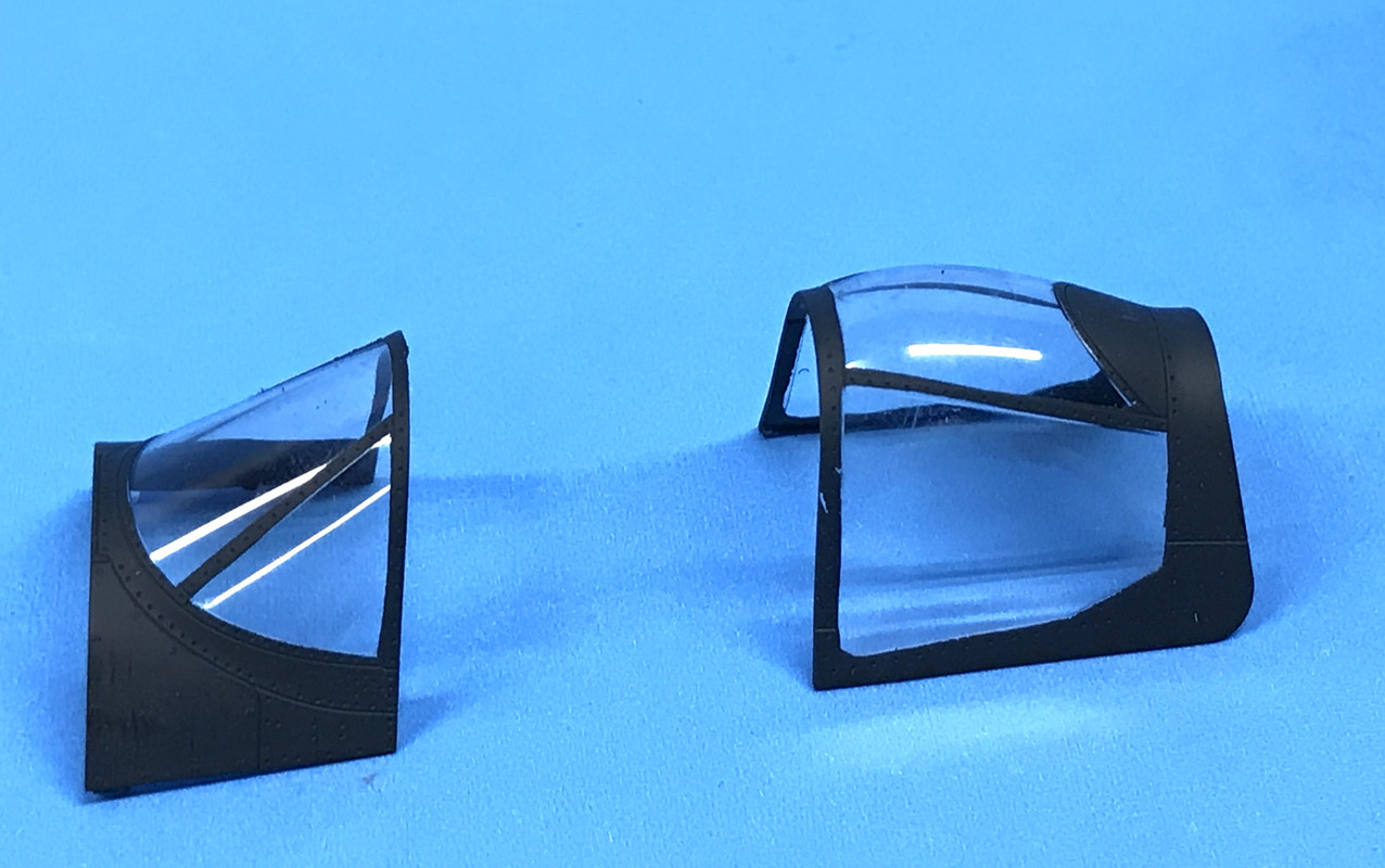
The results were gratifying. The Tamiya masks were very accurate only limited by your ability to cut them out correctly. In retrospect, I should a have left the masking in place on the outside until it was glued onto the plan to protect the glazing from anything. I may put some masking on them just for that purpose. It won't have to conform to the canopy frame, just protect the clear stuff.

I was trying to decide what kind of gloss clear I was going to use prior to decaling. I have Pledge with Future, Tamiya Gloss Spray and Testors High Gloss Clear Coat for model car building. I painted the rear of the test article with Tamiya and the front with Testors. I know how Future works. I like the level of gloss the Testor product produced. It's not Gloss Coat, it's a differently formulated product.

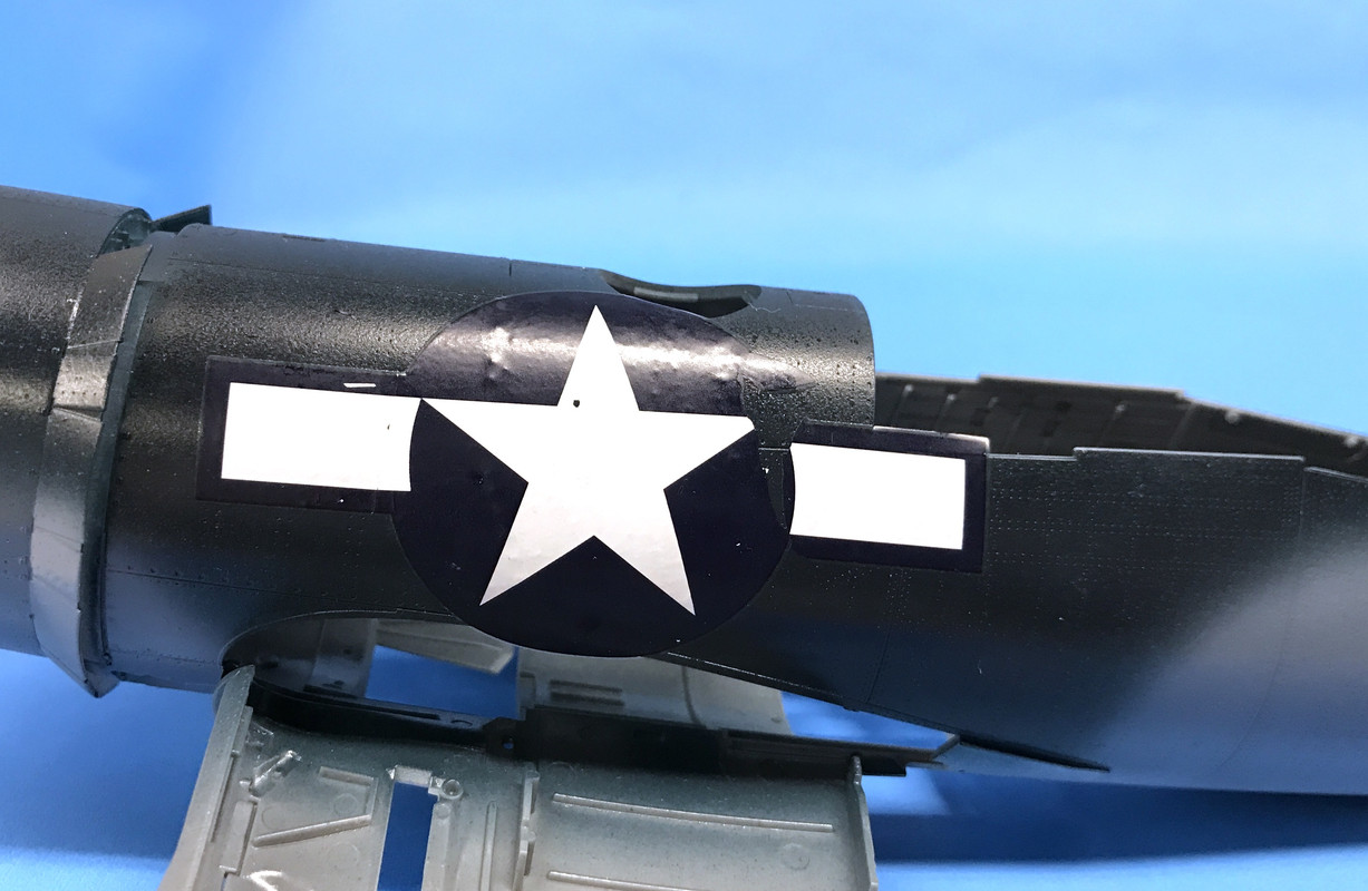
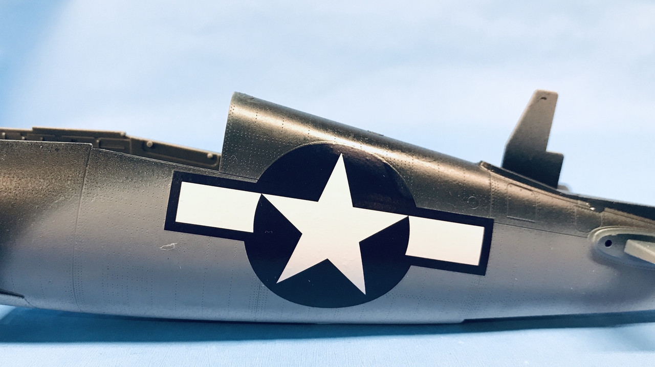
I then, using the extra decals from configurations I'm not building, applied a stars and bars to the front on the Testor coating. I read that the decals are thick and unforgiving, and they were right. Not only was it thick, but it fell apart in three places. I got it to settle in a bit with MicroScale products, but wasn't very pleased. I then coated all the decals my config was going to use with MicroScale Decal Film coating. When it dried I put another decal on the aft and this time it was successful. Here was the broken decal.
And here's the successful one.
I then glossed the wings on the two faces that are receiving the big decals. That's the only drawback with 1:32 planes (besides finding display space), the decals can be huge.

With the decal film coating, none of them cracked or broken in such a way as to make them unusable. The first one did crack, but with setting solution, it's not visible. Here is a shot showing both wings just after decaling before the setting solution finished working.
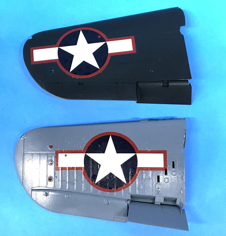
When fully dried, they did settle in pretty well, but do obscure some of the underlying details. I got a note from one of my buddies at the hobby shop that I should use AK Ultra Matte to re-coat after decaling. I will buy it if Marty recommends it. The decals have actual holes in them to enable some protruding details to show through. I was careful to not put the decal film liquid on these holes so they would be clear and not any trouble.

I then re-covered the pilot with some wet toweling so the gloss would get him, and sprayed the plane in the areas where big or complex decals were going.

And then the first diaster happened. To spray the plane, I was holding the plane by the cowl since it didn't get many decals, and then the engine separated from the plane!! I didn't realize that the joint was not that structural. 
To add insult to injury, when I grabbed at the fuselage which was falling away I grabbed the very tacky gloss coating and gave it some nasty fingerprints. 

I glued the engine back on, and let it set up and then went to repair the fingerprints. Luckily, they'll behind the big fuselage decals. 

And then the 2nd disaster hit. Engine separated again, and this time, engine and plane hit the concrete!! Speed ring detached from the front of the engine, that pesky landing gear door came off for the 4th time, a faux wing hinge broke off, and the two bottom exhaust sets broke loose.

It took me a while to triage the mess. I needed to reattach the exhaust with brass pins and did the same with the broken wing hinge. The gear door went back where it came from without protest. I got the engine back on with Testor Tube Cement this time to give it more manipulation time, and got a bit on the cowl behind the cowl flaps. I was able to touch up spray the sea blue to fix the glue smudge, and got it all back togeher. Whew!!
Alls well that ends well. It could have been much, much worse. The landing gear didn't get hurt. Those delicate wing fold regions were unscathed except for that fake hinge. Nothing in the cockpit was harmed, and nothing on the engine itself, even though it bounced around on a concrete floor. So I'm relieved.

I also got that all important P&W decal on the engine gear case.

I did get most of the stenciling on the wings' bottom, and the fuse with have a chance to dry completely before decaling it. So it was a productive and scary Saturday.

  • Member since
    November 2004
Posted by snapdragonxxx on Sunday, December 2, 2018 8:13 AM

Outstanding work and rescue!

Usually when something like that happens to me the resulting casualty is unrecoverable and has to be consigned to the recycling bin!

I personally would have invested in some insignia masks and painted them on rather than mess with decals and I do think Maketar Masks have some mask sets just for this...

and indeed they do

https://shop.maketar.com/?product=132-vought-f4u-1a-corsair-for-tamiya-kit

They also do the 1D and birdcage! I would choose the Kabuki tape option as that stuff doesn't suffer shrinkage as vinyl does and would save you lots of time messing about with gloss varnish, decal mediums, matt varnish etc.


James

JOIN OUR COMMUNITY!

Our community is FREE to join. To participate you must either login or register for an account.

SEARCH FORUMS
FREE NEWSLETTER
By signing up you may also receive reader surveys and occasional special offers. We do not sell, rent or trade our email lists. View our Privacy Policy.