Only two hours, but a productive two hours...
Found a great resource for the jet trailer problem. It's a company brochure who makes them and had all the dimenisions including the tire size. I screen printed the drawing and imported it into CorelDraw and scale the 132" rail length to 1:32. This then gave me all the rest of the measurements. The tires come out to .81". That works out almost exactly as a B-15 Mitchell wheel in 1:48, but the hub is all wrong. 1:48 truck tires come close also, and that may be the way I go.
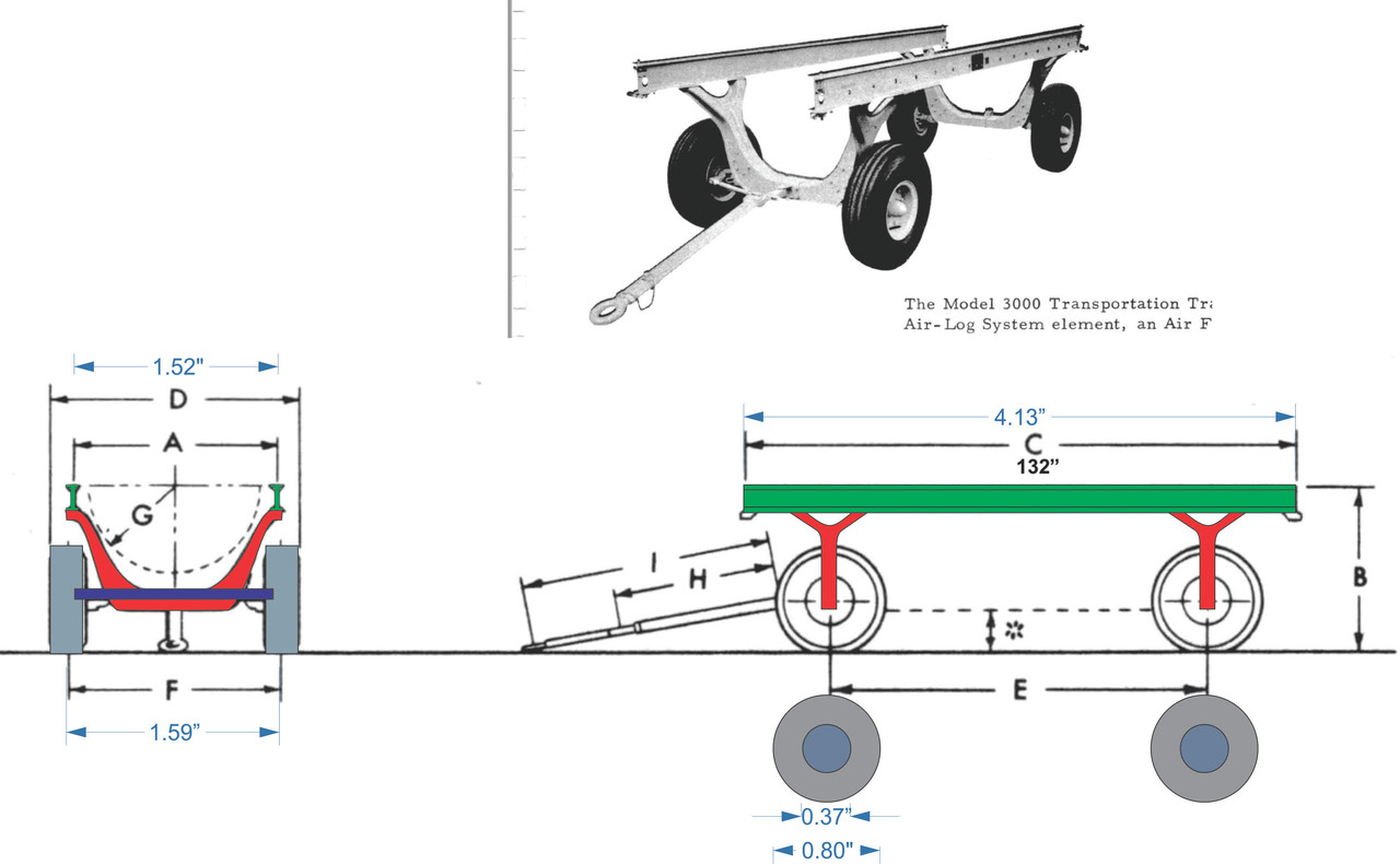
I have some brass I-beam that would work for the main rails. The prototpe rails aren't I-beams. They're specially made units that quickly connect to other carts and work stands. The company makes three styles. The positioning trailer, has smaller wheels and a parallelogram lifting mechanism that enables the operator to set the angles to remove and install jet engines into the air craft. Then there's the transportation cart, which is simpler with bigger wheels and connects to the positioning cart so the engine can be moved to the transport cart. This, in turn, connects to the work stand which had fixed legs. If pressed, I could do the work stand and solve the "wheels problem" completely.
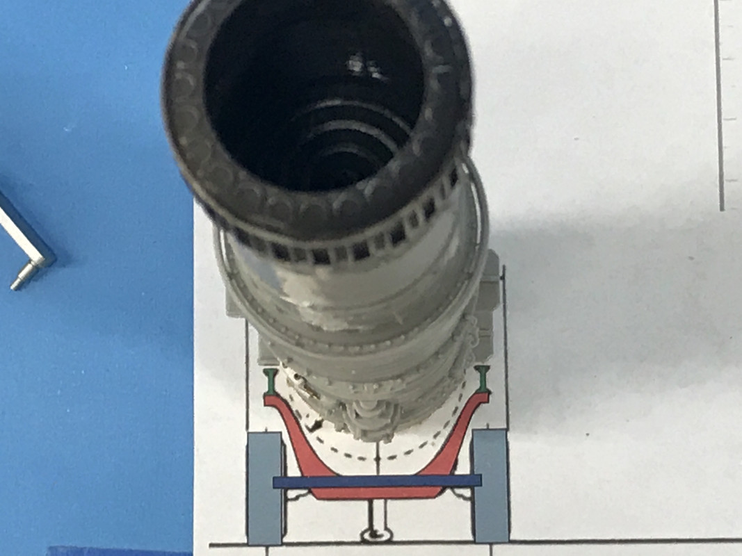
To test whether my scaling works with the model's engine, I printed out the drawing and set the engine on it. This checked the width which was perfect!
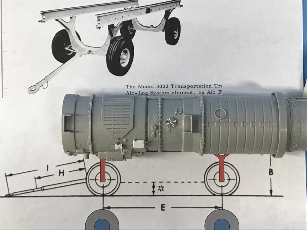
Then I checked the length. Okay also. So I was confortable that the scaling of the M-3000 Transportation Cart works with the J75 Engine.
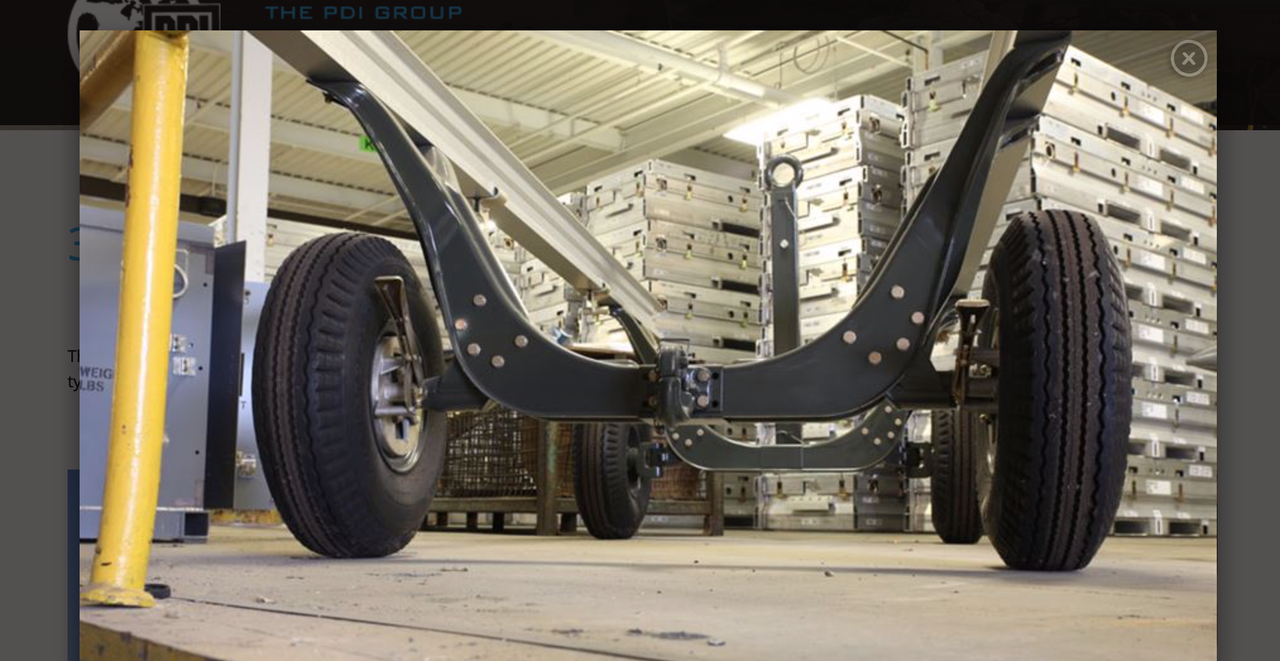
The cart suspension is not simple. It appears to be made out of steel stampings where the axle peices are riveted between two sides of the stamping. The stamping is closed on top with a (probably) welded piece. It will not be easy to scratch-build this. I can either make it out of styrene sheet or brass. I'll see how it goes. This pic is the rear. The front steerable wheels is more complex.
In discussion with Marty Schwambau at Scale Reproductions yesterday, he suggested that if I want to display the engine AND had the ass end of the plane complete, that I could cut off the afterburner section and put that into the plane. One of my pics the other day shows the engine just like that with the AB tailpipe removed up to the flame holder.
So I bit the bullet and sawed off the AB pipe with the micro-saw. It turns out that the simulated bolt circle, which I cut jut aft of, is the actual place where the flame holder is I I didn't screw that up.Needs som painting and TLC, but it's okay. To stand the engine vertically for this image, I made an adapter piece of some junk MDF with a hole in it to accommate the bulge at the compressor inlet so the engine would stand straight up without falling over.
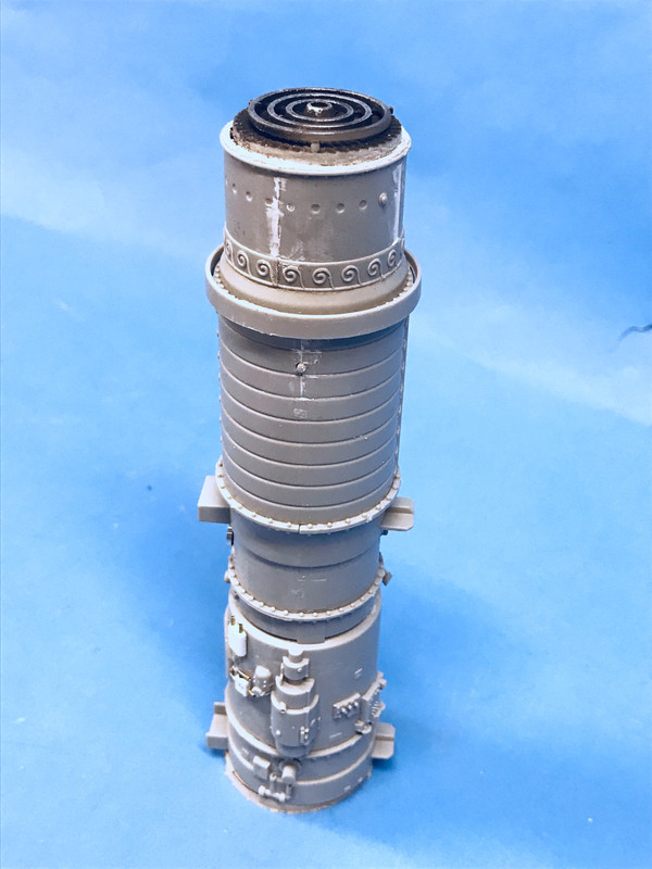
Since the engine is centered in the fuselage with the four lugs projecting from the engine proper, the AB section had nothing to hold it in. So I had to make some bulkheads to center the engine in the tail section. This took a bit of crafting.
I started with some card stock, tracing the rear-most tail section of the tail cone held together with a rubber band. This was not the size that would be needed since the bulkhead was going to be positioned further into the tail cone where it was narrower, but it was a staring point to get the contours right.
I drew center lines in both directions where I cut a hole that matched the AB pipe's middle dimension. I cut that hole in the card and trimmed it so it fit the AB nicely.
I cut the o.d. and then started trimming the diameter evenly just on one side until it fit decently into the spot that placed the exhaust's end just sticking out at the correct distance. I kept fitting unil it work and the center lines were still corresponding to the edge of the 1/2 tail cone piece.
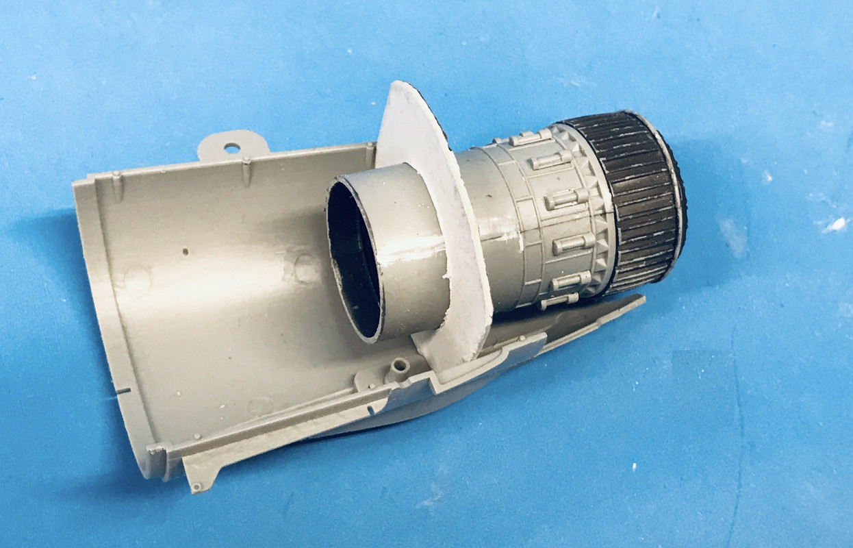
When it was finally right, I transferred the profiles to some 0.040" styrene sheet. I only traced the 1/2 that was correct, and then traced it again to make the other half. This was I was assured that the engine was properly centered. I cut the styrene by scribing with a #11 blade and breaking on the line. I glued each bulkhead half to their respective sides and tried it out.
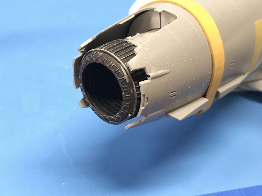
After gluing with solvent cement, I went back and hit it with thick CA to close any other gaps. I then followed up by glueing in 0.040" X .100" styrene strip so not gaps were visible. Lastly I closes some gaps at the juntion between the two halves with some more 0.040" styrene cut to the same contour as the bulkhead.
I painted it all with burnt iron.
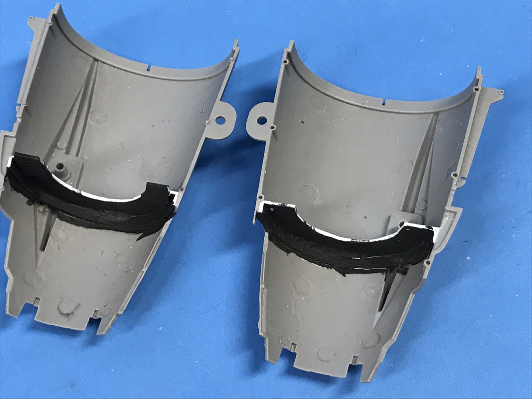
Here's the two halves fit together showing how the bulkhead appears from the outside.
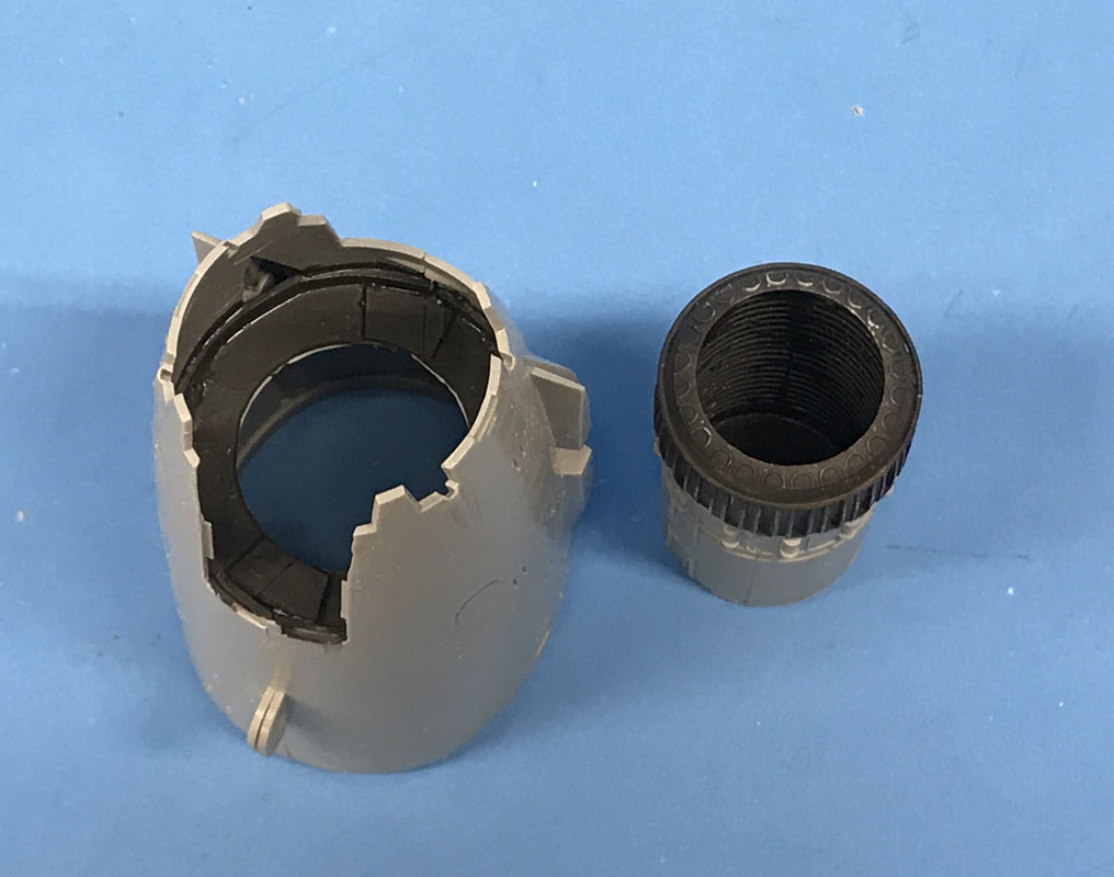
With this important mod out of the way, I can relax about detailing the rest of the engine for the display. The more I think about it, I would be so much simpler desiging and building the work stand instead of the traveling one.
To make the installation even more secure. I wanted to put some side stabilizes between the bulkhead and the outlet of the tail cone. I was next to impossible to find that distance on the tapered portion. So I took some Sculpey Clay and put a ball of it on the cone where I wanted to get the dimension, and put the AB in place and centered, pushing it into the clay. I ran out of time to fire the Sculpey to harden it. I'll do that tomorrow. I'll finish shape pre-shaped Sculpey and will glue it to the wall and the AB. This will perfectly secure it. I do the same for the other side.