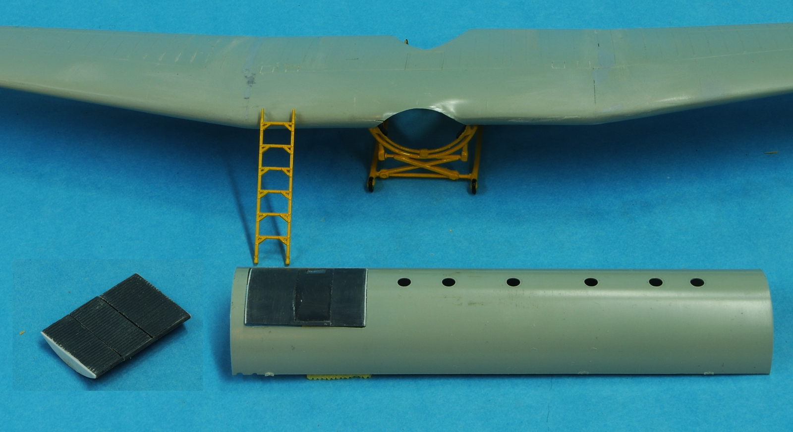
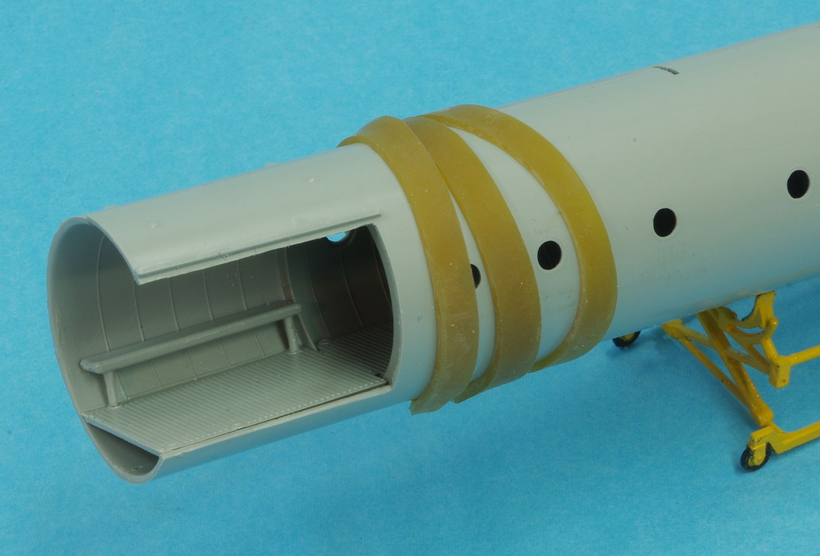
A little work has been done on the Italeri 1/72 Horsa. I have a spare kit that I picked up somewhere that someone had started. The wings were poorly joined and they may have given up at that point. In any event, the carpet monster, if not doomed, at least has suffered a major setback. It also allowed me to take a different approach on the cargo door. Italeri's plan was to cut out the door, and they supplied separate parts to make up the door. The parts didn't look like what the door looks like in pictures, and I didn't see how you could load wheeled vehicles through the side door when there was a big gap in the ramp where the door was. Also, I believe the door was inset, and slid sideways to open. The steps Italeri supplied did not appear in any photos, not even in the rear door. All the photos show ladders being used when the door was open, and the doors are never visible when they are open. To make something that looked plausible, I made up a removable section of ramp surface that fits over the door opening to be used when cargo is being loaded or unloaded. There may well be steps on the back of the door in the ramp, but it will not be visible on my model. I used parts from the started kit to make the cargo door and the needed ramp parts, you can tell what they are by the dark plastic. I capped the ends of the new cargo door with plastic card. As I saw in some photos, the man door in the cargo ramp is not flush with the outside surface, but inset a little, so it can slide. I sure hope I interpreted all those photos correctly. I actually did, after several hours, find a photo of the ramp with the door section covered by a section of ramp.
Before I worked on the cargo door I assembled the wings, which was a lot like working with vacuform parts. I matched up the upper surfaces as well as possible, then tacked them in spots with CA on the inside surface. When the alignment looked good I applied a heavy pass of CA over the entire inside joint. Next the lower wing parts were attached. Because of the angle of the join, there was still some filling to do so the upper join areas were taped off and a thick layer of Mr. Surfacer 1200 was sprayed on. That was left to cure for a day and then sanded smooth.
I next went to the fuselage parts and cleaned up a few sink marks with CA, then joined the left tail to the left main fuselage and the same for the right side. This gave me the opportunity avoid misalignments at the join. I cut off the alignment pins so I could lay the sides on a glass plate to insure good alignment.
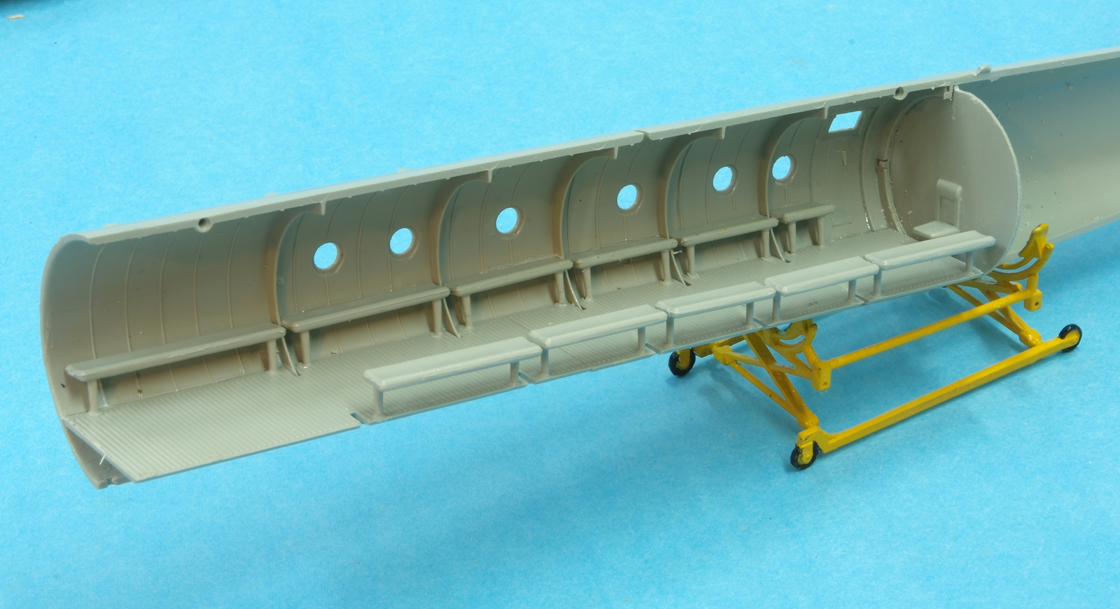
With the fuselage halves together the two floor sections which were previously joined were set in, and then tack glued to the right fuselage half where I could reach it in front. That insured the floor was level, as there were just some faint lines in the plastic where it might attach. The right front seat was installed, then the halves were separated and the floor was glued down the right side. The rear bulkhead was next installed in the right fuselage and the fit was checked. In order to get the fuselage to come together in that area a generous amount was removed from the right edge of the bulkhead, there is no penalty there because there is a ring bulkhead in the fuselage that covers any gap and you will need your borescope to see it anyway. You do have one, don't you, a borescope? As you can see, the seats were then installed.
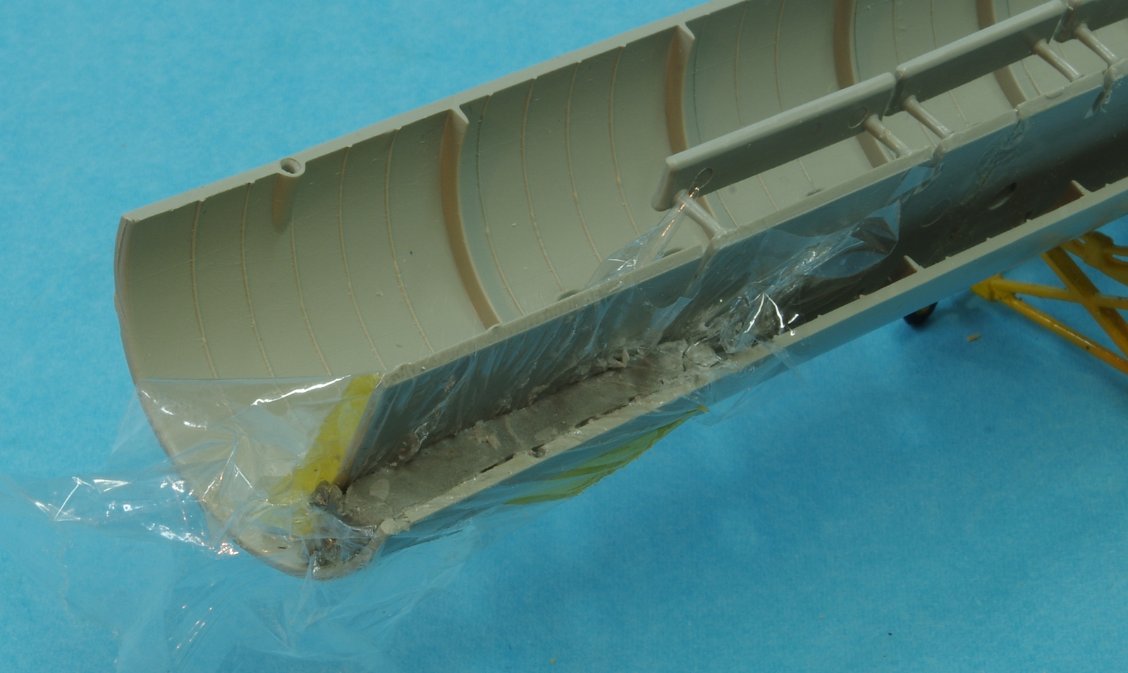
The last photo shows the beginnings of making some weights to fit under the forward section of the floor. Plastic wrap is pressed in to cover the plastic and Epoxy Sculpt has been formed into the cavity. Once it cures the resulting shape will have silicone mold material poured over it and in that mold lead will be melted.


