Hi Guys,
Wel, it's been a busy few weeks here, but I've been plodding along on the ol' DML Pre-Zimmeritted King Tiger, andhere's the ready-for-paint shots, along with a review of my impressions of the kit. My opinion is mixed, to say the least!
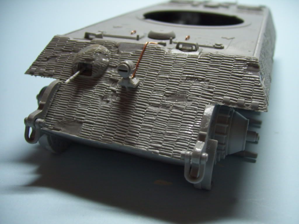
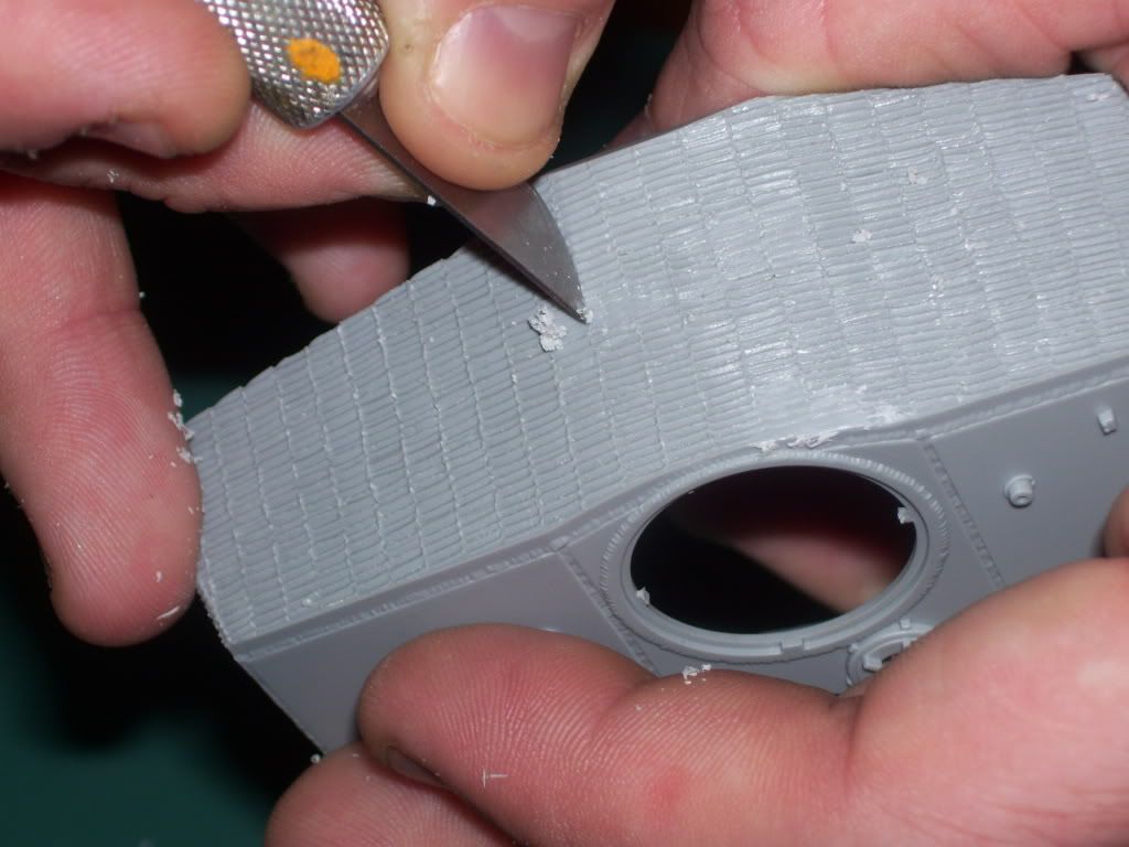
First, picking up from the original post, here's the shot of the front hull, which shows that you can indeed "chip" and damage the zimmerit. I'll show how I did this in a minute.
Here's the mini-chisel set from Micromark. A VERY handy set of tools!
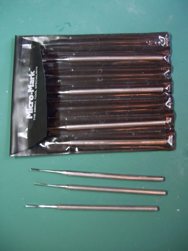
Just a sample of Ye Holy Tools of Zimmerit of Destruction.(sound of angelic choirs in background)
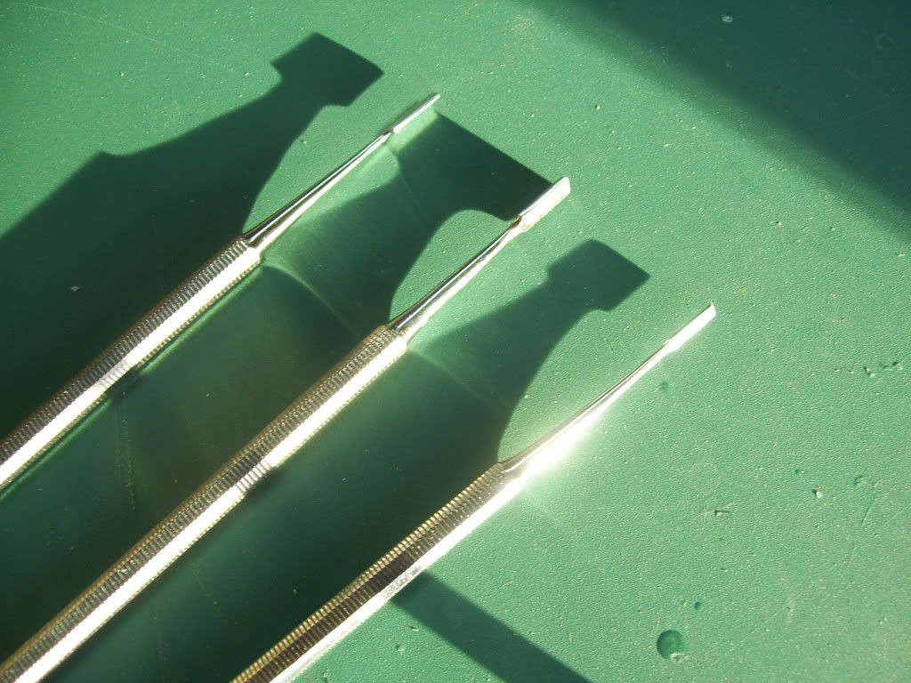
First shalt thou take out the Holy Chisel. Then, shalt thou count to three. No more. No less. Three shalt be the number thou shalt count, and the number of the counting shall be three. Four shalt thou not count, nor either count thou two, excepting that thou then proceed to three. Five is right out. Once the number three, being the third number, be reached, then, wield thou Holy Chisel towards thy hull, which, being naughty in My sight, shalt be chipped.
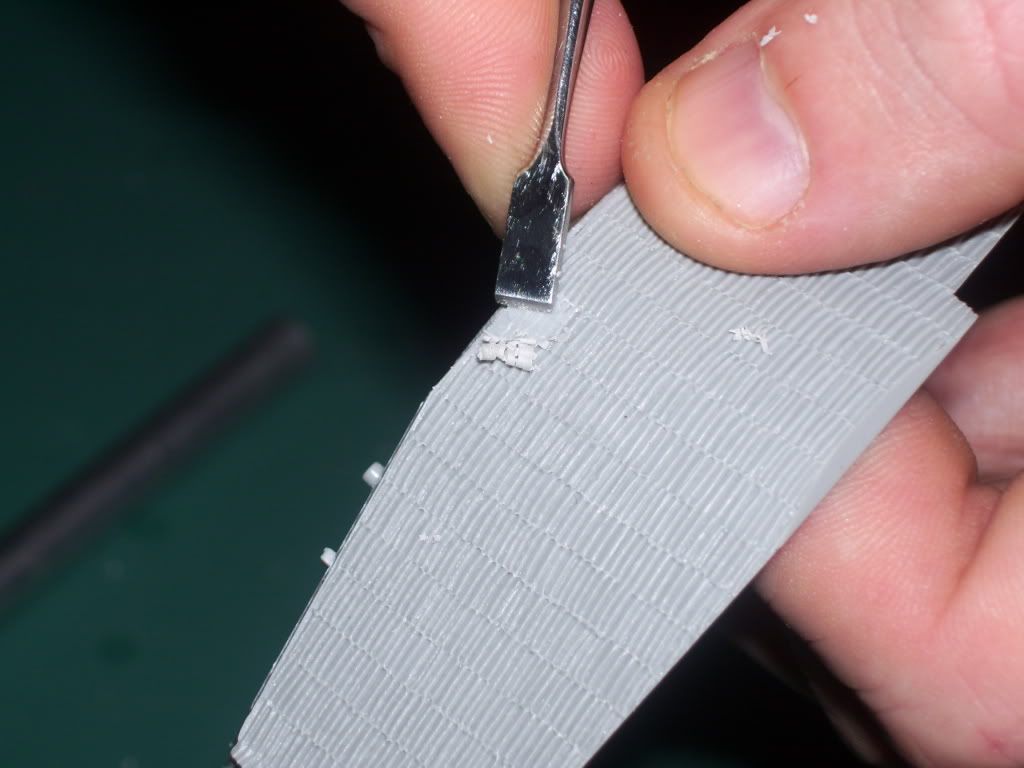
I also used the Less-Holy-but-Still-Venerable Xacto Blade of Laying-Waste to scrape less-square sections, and to smooth the chiseled portions--but only on a Thursday, and never before noon, as required by The Law.
OK; things to add... (Sorry, I'm in this "Monty Python" groove today...![Smile [:)]](/emoticons/icon_smile.gif) )
)
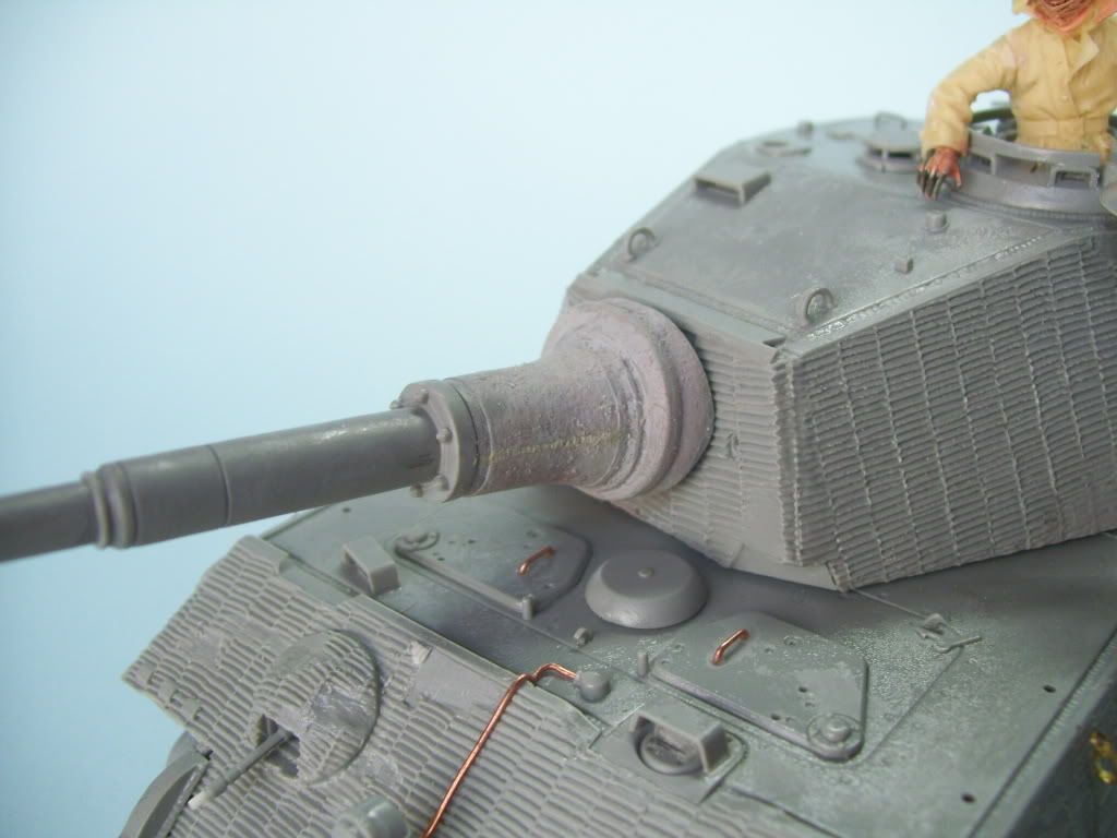
The weld on the mantlet--this is really very subtle. I have seen this added in much excess, looking like a major hull weld; go very subtle here. I added it with a light dabbing of Squadron's White putty. I also roughed-up the mantlet texture with some Mr Surfacer 500.
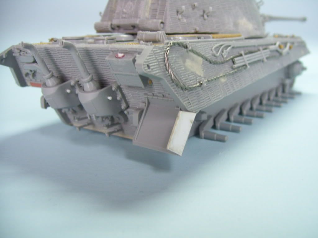
Don't forget the lifting lugs on the rear muffler guards...I also scratched a bent fender; you can't see it in the photo but it has all the requisite bolts detail in it....
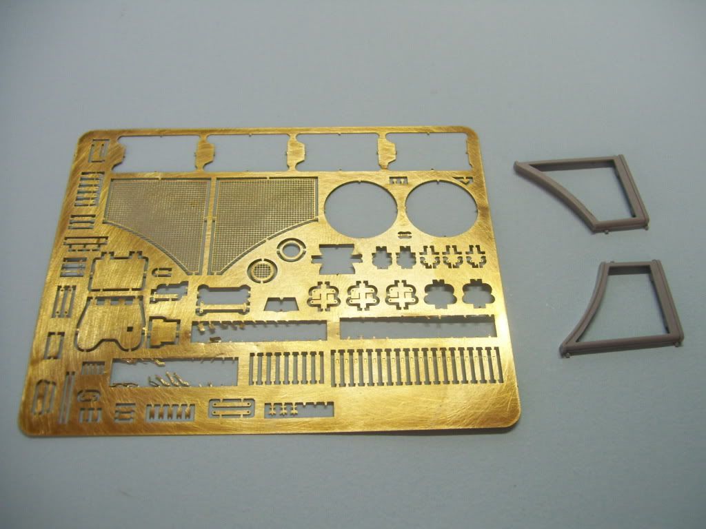
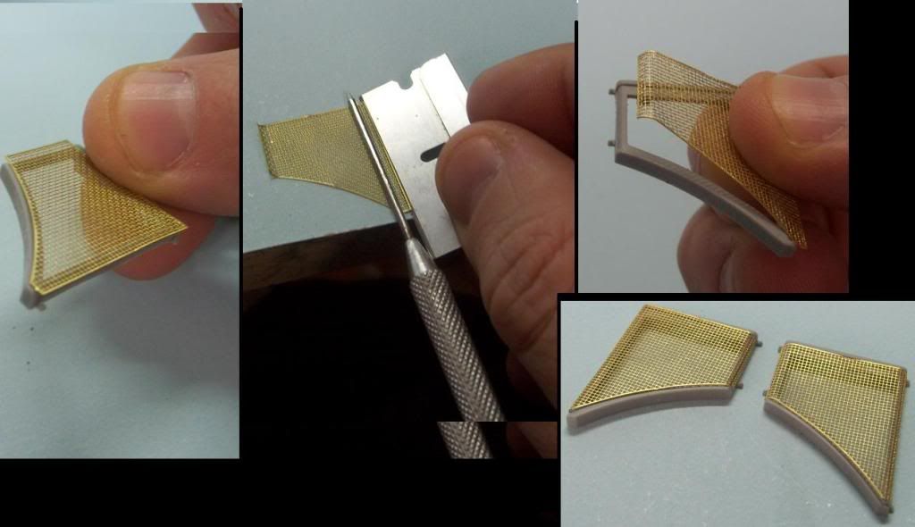
OK--next, for Tony, an illustration of how to do engine screens. Here's the PE and the parts you have to bend the PE around.
And, in composite, how I bent the PE around a pick using a razor blade and knife blade. It;s important to remember that you should look for a diameter slightly smaller than the curve that you actually want. Some strange law of modeling physics says that if you choose the exact same diameter, the PE wiil always be slightly under-bent!
Now here comes the mini-rant. Mostly this has to do with my disapointment (disillusionent?) with the touted "extra's" in this kit.
First, I have read some other notorious rants against DML/Dragon directions, but lemme tell ya--I can empathize with the author! The "photo directions" used in this kit are unforgiveably vague. The lighting of the photos often precludes the possibility of seeing the detail needed to correctly position a part. Secondarily, the added PE parts are for the most part simply illustrated as how-to-assemble, but often are not pointed out as to where they are to be used. And there are a LOT of unused PE parts left over that leaves one scratching one's head where and what might have been possible, or missed! The "working clamps" were, for this experienced modeler, impossible to manage or assemble; I wound up substituting some Royal Model clamps instead.
The debacle of the directions and PE are unquestionably a cost-cutting decision by DML, as they are simply using the "old" directions, modified with some new illustrations, but they are, IMHO, wholly inadequate.
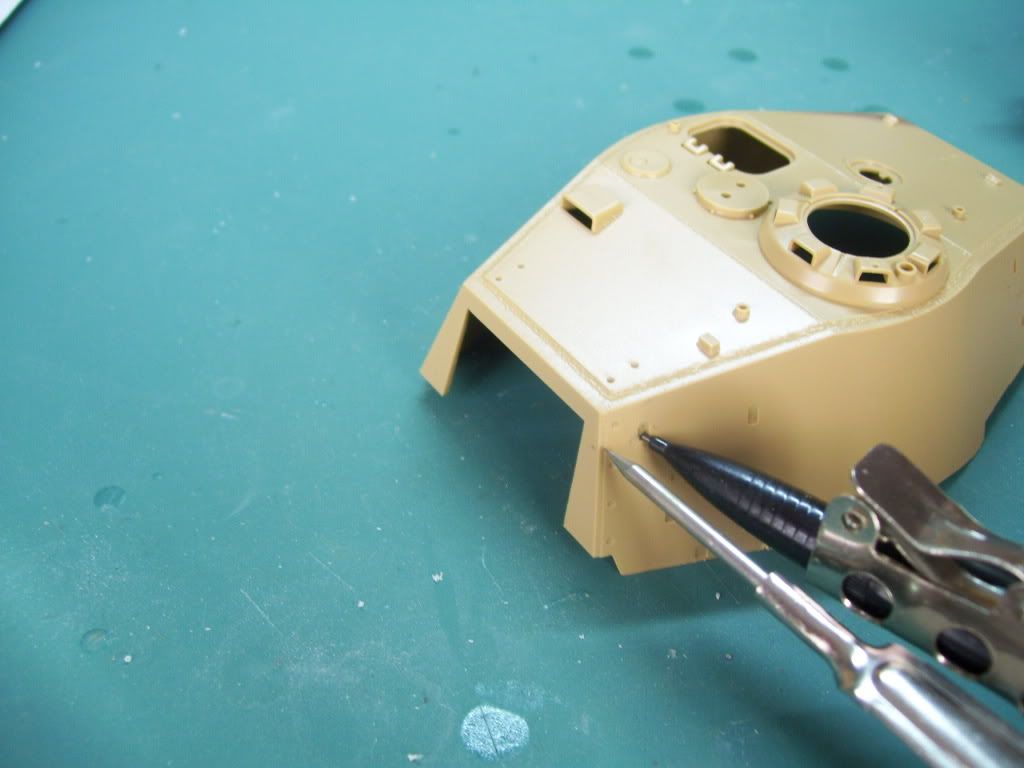
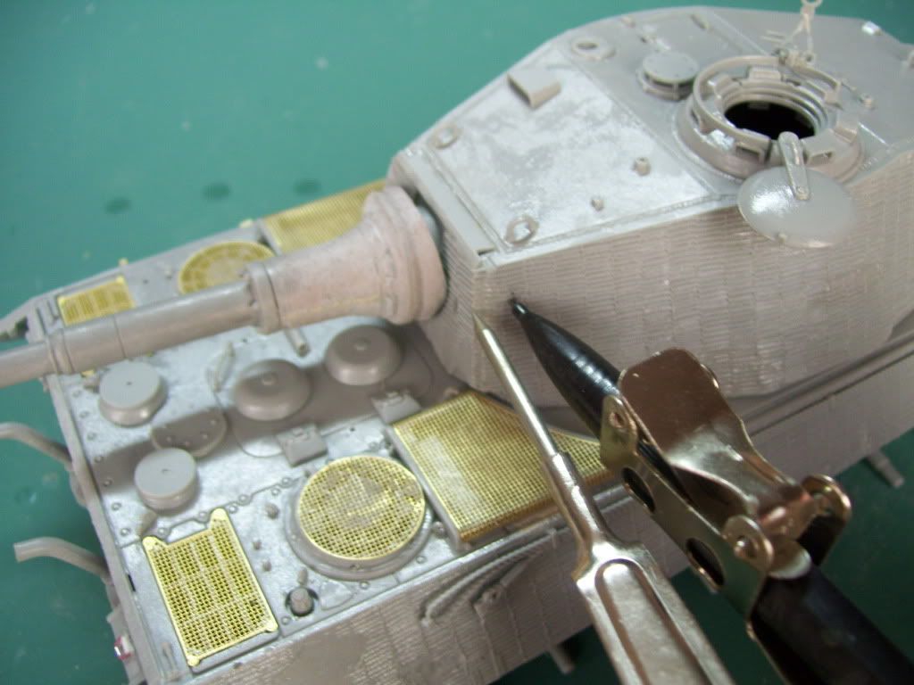
Here's another bummer--the lack of locating points for the track hangers on the turret. Could not DML have put some punch-through marks behind the turret wall (much as they do in their fenders) so as to retain the possibility of those who want to build one of the earliest Tiger II's which came without spare track hangers? True, you can glue the tracks onto the turrret side first, and then add the hangers inside the cut-outs, but I found this to be an untenable option for the finish procedures which I have planned. This is a major PITA of the kit in my opinion--especially if you don't want to portray the kit with a full complementof hanging spare tracks!
In any case, I used a compass and a Tamiya turret to locate the hangers.
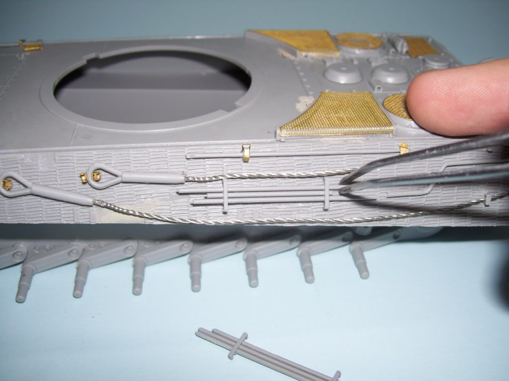
And this really ![Censored [censored]](/emoticons/icon_smile_censored.gif) 'ed me off. It's nice that DML has included extra parts and real cable fo rthe towing cables--but they realy goofed on the dimensions here. Check this out--if you use the stand-alone cable ends, the dimensions are off on them--I could NOT properly fit the cleaning rod parts once they were affixed!
'ed me off. It's nice that DML has included extra parts and real cable fo rthe towing cables--but they realy goofed on the dimensions here. Check this out--if you use the stand-alone cable ends, the dimensions are off on them--I could NOT properly fit the cleaning rod parts once they were affixed!
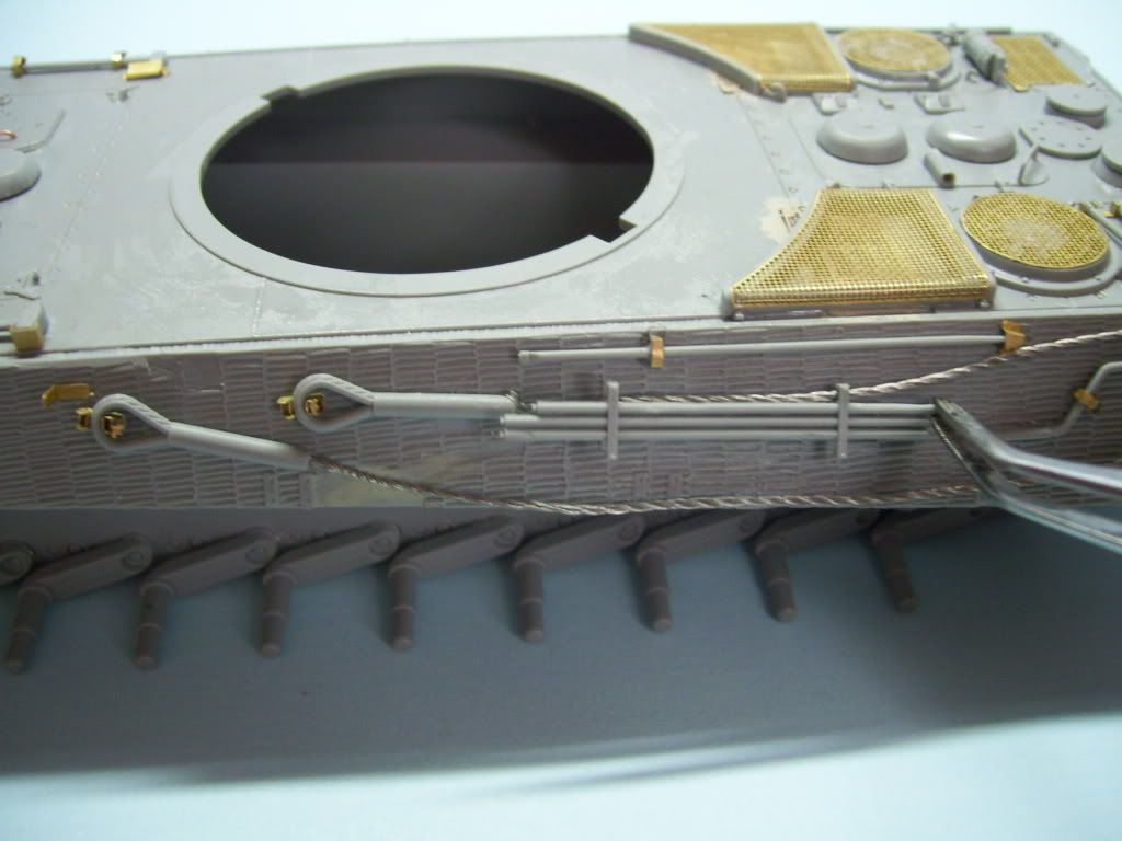
Neither one fits!!
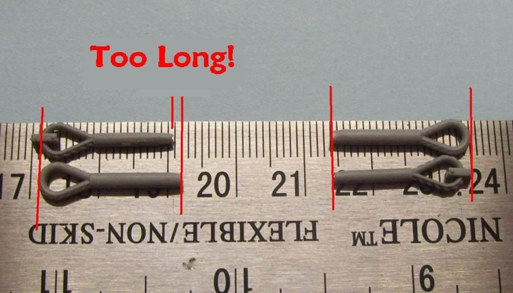
The reason for this is evident in this comparison--if you look at the set of stand alone, and molded cable ends on the left, notice how, if you compare the length of the actual cable ends, the stand-alone ends are actually longer by about 2mm!!! ![Banged Head [banghead]](/emoticons/icon_smile_banghead.gif) You can see in the right-hand parts that when they engineered this part, some bonehead measured the entire part, clamps included and used THAT for the measurement!
You can see in the right-hand parts that when they engineered this part, some bonehead measured the entire part, clamps included and used THAT for the measurement!
I'm sorry; I know I should be grateful for these added "extra's", but this kind of engineering strikes me as just plain sloppy! And--MEA CULPA!!--Yes, I should have "test fitted"--but hey man, this is supposed to be like a state-of-the-art kit! Slide molding and all, you know?! Additionally, when you use the provided wire as I have, the wires themselves are too big for the diameter of the cleaning rod kit parts. When you try to attach them over the wire, thet stand "off" the hull. I wound up having to use a needle file to thin and enlarge them considerably; in fact, down to almost breaking through them. Again, I expected more here.
So, I would up shortening one cleaning rod, and then moving the entire part/assembly bacl a few millimeters to fit the part. So much for dimensional scale accuracy! ![Sigh [sigh]](/emoticons/icon_smile_sigh.gif)
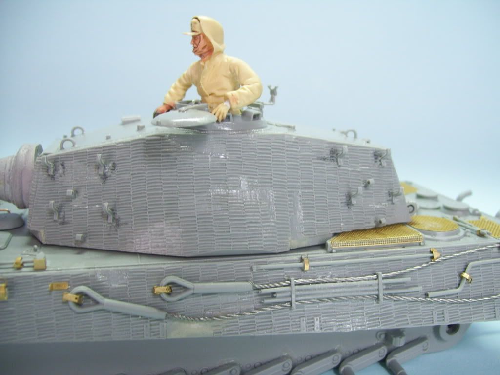
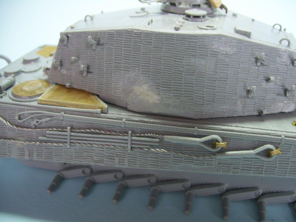
So in the end, as I prepare for painting the base coat, I have mixed feelings about this kit, For my money, if I build another one, I would use nylon thread for the cables, and really pay attention to those darned cable ends, as well as possibly using a whole other Eduard or similar PE set.
Manny, did you encounter any of these problems?
I'll be busy tonight until later, but questions and coments are welcomed--I'll try to answer when I get home! Thanks for looking guys! ![Big Smile [:D]](/emoticons/icon_smile_big.gif)