SEARCH FINESCALE.COM

Enter keywords or a search phrase below:

1/6th scale SDKFZ 222 armored car project

31287 views
59 replies
1 rating 2 rating 3 rating 4 rating 5 rating
  • Member since
    April 2005
Posted by armourguy on Wednesday, August 21, 2013 12:38 PM

Thanks guys, It has been a long time since I had any updates and I didn't forget about this build. I have been working on tooling up the gun carriage and mount. Here are some sneak peak images of the masters.

Once I have some more masters ready the parts will go into molding. Also after all the parts are completed I will add the mount to the parts catalog. More to come!

  • Member since
    October 2010
  • From: Hoodsport, WA
Posted by Dogfish_7 on Thursday, July 11, 2013 4:30 AM

Bow DownBow DownBow DownWow

Bruce

  • Member since
    July 2003
  • From: On my kitchen counter top somewhere in central North Carolina.
Posted by disastermaster on Tuesday, July 9, 2013 5:28 AM

Ok, You can stop now. You've finally killed me.

                                                     http://gfxlovers.com/smilies/imgs/guns/guns012_2.gif

 https://i.imgur.com/LjRRaV1.png


  • Member since
    April 2005
Posted by armourguy on Saturday, July 6, 2013 12:09 PM

I made more progress to the model.

I was able to complete the grill work.

The 222 featured a very complex grill work that was unique to the 222. The grill work was comprised with a honey comb style pattern.

The grill work is all scratch built out of sheet metal that was all cut, shaped, and fitted by hand.

The whole fabrication was very time consuming and tedious, and is one of those parts that once complete is something that I don't want to go through again.

On the corners of the grill are two access hatches. These hatches are non functional on the model, but have all their detailing present.

After the grill work was completed / mounted I then turned my attention to mocking up the turret.

The turret is assembled out of the kit supplied turret panels. The turret was very straight forward, but to help out it is a good idea to label the panels as to prevent from getting confused.

More work will be done to the turret, which will be added as the build progresses.

a quick video update was added to youtube: http://youtu.be/swFzTCuBd1M

Also more pics were added to the youtube page.
http://www.facebook.com/EastCoastArmory

I will now be focusing on the fabrication of the gun and gun mount. More progress to follow!

  • Member since
    April 2005
Posted by armourguy on Wednesday, June 12, 2013 9:59 AM

plastickjunkie

 I can just imagine how the engine compartment will look like.

Thanks, but due to time constraints...and lack of any good references on the Horch engine I will not be going with the engine bay details on this one.

 I made more progress on the model's interior basically completing the hull portion of the interior.

The rear floor boards were added. Along with the floor boards I fabricated the transmission cover, and the rear storage boxes.

On the car's front I added the last of the electrical details. This would include the Battery and the steering column fuse boxes.

For the battery I used a resin battery from armorpax. The battery casting is very nice and saved alot of fabrication time. The only details that I added to the battery was the mounting strap, and the battery terminals.

The model's doors were also completed. For the doors I used the kit supplied versions. The kit doors were the correct size and shape.

To make the hatches functional I used a set of functional resin German AFV hatches from Panzerwerk. The Panzerwerk hinges are pre drilled and are nicely detailed. To fit the doors I needed to drill out the molded in fasteners and replace them with metal fasteners (because of the weight of the doors they needed extra strength)

On the hatch interior I added all of the details. These would include the handles, bread bag mounts, storage canister / mounts, and the locking mechanism.

On the 222 the bread bag mount, storage tube mount and handle were all connected to each other by both welds, and a fastener.

On the model I assembled it the exact way it was on the real vehicle by fabricating all the parts out of metal that was soldered together and bolted.

Because of the hull angles on the 222 gravity would pull the side doors open. To solve the issue I had to make the latch system functional.

To open the hatch from the inside you rotate the handle...

but because of the gun and turret getting access to the hatch from the outside will be very difficult... so Like the real vehicle I had to design the system to be operated from the exterior of the vehicle with a key.

For the model I use an Allen wrench to operate the lock. The system works very well. and looks very similar to the type of lock on the real vehicle.

After the hatches were mounted a DML bread bag was fitted to each door.

A video update was added that shows the functionality of the door mechanisms further. http://youtu.be/Kdu6gNxpKPY

Also more pics were posted on the facebook page: http://www.facebook.com/EastCoastArmory

these details were the last things holding me back on the model before I could start on the gun. With them out of the way I can now focus on mocking up the turret and tooling up the gun mounting system. More to come!

  • Member since
    November 2008
  • From: Central Florida
Posted by plasticjunkie on Friday, May 31, 2013 10:24 AM

armourguy

Your work is just simply AMAZING! The pictures look like a full scale vehicle and not a 1/6 scale model. Attention to detail is just mind blowing. I can just imagine how thwe engine compartment will look like. You sir are a master builder! Toast


 GIFMaker.org_jy_Ayj_O


Too many models to build, not enough time in a lifetime!!

  • Member since
    April 2005
Posted by armourguy on Sunday, May 26, 2013 12:36 PM
More progress was made to the model's interior
I completed the instrument panel, and the radiator. Both of these new components were added to the catalog. 
http://eastcoastarmory.com/222.htm
SDKFZ 222 Instrument panel set. 
The set also comes with the labels and the gauge faces. All of the gauges were recreated and scaled down from the real 222 gauges
After the panel was painted I added the clear epoxy to the gauge lenses and mounted the panel to the model. 
SDKFZ 222 radiator / cooling fan set. 
The set includes both the radiator and the cooling fan. The fan can also be made to spin.
On the 222 the radiator fan was spun by a pulley wheel that connected to the engine's out put shaft. 
 
After the radiator was painted the radiator was mounted into the model 
In the fighting compartment the radiator has a protective grill mounted to the firewall
On the model's front portion I also added a armorpax german tetra fire extinguisher and a spare Notek light. The Notek light is a spare I had on hand from the DML schwimmwagen kit. From what I've seen on the restored 222 in the Littlefield collection, the internal fire extinguisher is painted red.     
A video update was added to youtube, and more images were posted on the facebook page. 
https://www.facebook.com/EastCoastArmory
http://youtu.be/JgtVGxi1AVc
I will now be focusing on the the last of the floor boards and will then be able to turn my attention to the doors and the gun / gun mount. More to come!
 

  • Member since
    April 2005
Posted by armourguy on Wednesday, May 15, 2013 9:32 PM

More progress has been made on the 222.

I tooled up come more interior components and added them to the catalog East Coast Armory -- 1/6th scaleSDKFZ 222 armored car detail upgrades

222 interior hand pump set.

German AFV interior non hinged periscope detail set.

Resin German AFV interior right hand hinged periscope set.

Resin German AFV interior left hand hinged periscope set.

Before I was able to get the body to paint I had to first fabricate the mounts for the rear grill work, and the counter sunk fastener detail. These fasteners had to be added now because of the exposed nut and thread detail that is exposed in the interior.

After the last of the interior mounts and visors were added the clear resin visors were masked up and the body interior went into paint.

Starting with the primer.

For the interior base coat color I used a cream colored off white color as, that is the color that I have seen on many WWII german AFV including the resorted 222 in the littlefield collection.

To best paint the body I tied the rear portion with a wire and suspended the body on a clothes line.

After the base coat was dry I added the weathering. After the weathering was added the body was mounted to the chassis. In addition to the mating of the hulls I began to add some of the crew equipment. More will be added as the build continues.

As I mentioned in an earlier post the body mounts to the chassis via fastener straps like the real vehicle. No glues were used in this procedure.

More images were posted on the facebook page, https://www.facebook.com/EastCoastArmory?fref=ts

I will now be focusing on the remainder of the floor boards, the dash board, and the radiator details. More to come.

  • Member since
    April 2005
Posted by armourguy on Friday, April 26, 2013 2:16 PM
I made some progress on the fighting compartment interior detailing. 
All of the interior details were scratch built, and most of the parts are all fabricated out of sheet steel.
One thing that I noticed on the real vehicle is that the interior detailing is not mounted directly to the body, rather they are mounted to elevated plates. These large plates made it easier to scratch build in that I add the details to the panel and then mount the whole panel to the interior. 
The interior detailing is mainly made up of mounts for crew equipment, weapons and ammo cases for the MG34.
Both the left hand and the right hand have different mount layouts, and are not symmetrical.
Even on the upper panels of the body there are racks for the MG 34 barrel cases and the a wire cutter.
I have stocked up on most of the crew equipment and weapons needed for this build. All of the mounts are functional and will mount the parts when added. Of all of the mounts I fabricated my favorite is the grenade ready rack. 
It holds 6 potato mashers in the rack in a staggered layout. (when they are mounted for real in the model I will tuck in the fuse string...would be bad to have one get snagged Embarrassed)  

All of the equipment will be added to the interior after the interior is painted and weathered.  
  
A youtube update video was also created explaining the mount detailing further.  
http://youtu.be/KGJh8ZxNCDM
As well as more images were posted to the facebook page
https://www.facebook.com/EastCoastArmory
I will now focus on the front portion of the cab detailing. More to come!    

  • Member since
    April 2005
Posted by armourguy on Friday, April 19, 2013 2:11 PM

Thanks guys,

It's been awhile but I have been working on the 222's interior cabin detailing.

The rear firewall was fabricated out of lexan and mounted. The center of the firewall is the grill work for the radiator. This will be fabricated after the body is mounted to the frame.

While on the radiator I fabircated the radiator mount and affixed it to the frame.

All of the interior joints had their weld bead details epoxy sculpted on. This not only gives detail, covers up any seams, but also gives a little strength to the body.

Towards the front of the hull I fabricated the mounts for the dash board / instrument panel. The instrument panel master has been completed and will soon be going into mold. Once complete it will be added to the product line.

The 222's body was unique in that the body was comprised of two halves, the first half comprised of the fighting compartment, while the other comprised of the engine room. The two halves were joined by a flange towards the rear of the fighting compartment.

To replicate this on the model I glued together two plastic angles and added brass micro bolts and nuts to them. Once the flanges were ready they were installed to the hull interior.

Because of the two halves there is a seam line visible on the exterior of the body. To replicate this I scribbed the lines with the Dremel multimax.

Also on the hull of the 222 had an overhang where the upper hull angles meet the lower hull angles, to replicate this on the model I added a styrene square stock to run along the top panel of the body. The square was then blended in to the body via body work.

On the front sides of the body the kit has two cut outs for the armored visors. The cut outs for the visors are too large though, to reduce their size I added 1/8 inch thick styrene bar stock to the cut outs. Because the stock was the same thickness and material as the body plastic it was easy to mount and to blend in. Now with the holes adjusted I can fabricate the interior visor detailing.

In addition to the detailing I have also made the cuts for the grill work and the engine hatch. These cut out required very accurate cuts and were performed with the Multimax and dremel.

The grill work will be fabricated out of sheet metal after the body is mounted to the chassis.

The engine hatch and the engine access hatches have their hatch wells added.

I also made a quick youtube tutorial on how to fabricate the hatch wells,

http://youtu.be/fKVy5KmJkK8

On the lower rear portion of the body I cut out the lower air intakes, in addition to cutting them out I added the armored ductwork to them. The ducts are fabricated out of sheet metal.

I will now be focusing on the interior mounting detail for the grenades, and other accessories.

Once compete I can paint the interior and start with the mounting. More to come!

  • Member since
    January 2007
Posted by the doog on Friday, April 19, 2013 10:12 AM

uhhhhh...excuse me while I pick my jaw up from the floor....!

  • Member since
    January 2010
  • From: St. Louis
Posted by Shawn M. on Tuesday, April 16, 2013 3:18 PM

truly great work

I love the smell of plastic in the morning

  • Member since
    May 2005
  • From: Dublin Rep Of Ireland
Posted by terry35 on Monday, April 15, 2013 4:54 PM

Amazing.

Terry.

  • Member since
    April 2005
Posted by armourguy on Wednesday, April 3, 2013 11:28 AM

Thanks Shawn,

I made some more progress on the build.  Since the last update the floor boards were painted and weathered along with the chassis.
The pedals, control sticks, and steering column were all added.    The seat was also painted and weathered.   Mounted just behind the driver's station is where the gun mount will be mounted. To mount the gun to the chassis this is done via a mounting hard point. The hard point is a strong mounting surface that gets mounted to the chassis. The bottom portion of the mount is reinforced with bulk heads, and the top portion will be covered with diamond plate after the cab get mounted. The component itself is fabricated out of lexan and styrene. After the part was painted / weathered it was mounted to the chassis    On the rear portion of the hull a sid plate was fabricated and mounted to the chassis. The skid plate protects the engine from damage. The plate itself is all fabricated out of sheet metal.    A

youtube update video was made and explains more of the progress. Also more images were added to the facebook page
http://www.facebook.com/EastCoastArmory 

http://youtu.be/4bVIPgqdfSM 

with the driver's station now complete, I have now turned my attention to the interior of the cabin. Once complete the cab will be mounted and I can then start on the gun and gun mount. More to come!

  • Member since
    January 2010
  • From: St. Louis
Posted by Shawn M. on Thursday, March 28, 2013 12:54 PM

awesome details

I love the smell of plastic in the morning

  • Member since
    April 2005
Posted by armourguy on Wednesday, March 27, 2013 10:35 PM

I was able to make more progress to the model.

With the basic body assembled I turned my attention back to the chassis frame. Before I was to progress any further I put the frame through it's painting processes. Because of all of the nooks and cranny's that are present on the frame, painting the frame at this point will ensure that all of the frame is completely covered in paint.

Starting with the primer

The by it's base coat of Panzer Grey

After the frame was painted it was time to add the last of the break lines and lube plumbing lines.

Both sets have also been added to the catalog http://eastcoastarmory.com/222.htm

For the break lines the 222's breaking control lines were facilitated via steel cables that ran exposed on the exterior portion of the frame. These cables would exit from the yolk and would be guided to the four brake drums

where the lines enter their guides they are protected via a rubber boot, on the set I used pre-tinted flexible resin for these parts. Because of this material the parts have their natural "rubber" look to them and don't need to be painted.

After all of the lines were added It was time to fabricate the model's floor boards.

For the floor boards I used sheet stryrene for the base and vacuum formed sheet styrene diamond plate for the surfaces. Clearances were cut into the floor boards for the hull mounting brackets, pedals, control stick levers, rocker arm wells, and the front differential.

On the real 222 the front differential a hump was covered by a sheet metal hump. On the model I also used Sheet metal for the part which was soldered together and mounted to the plastic floor board. In addition to the hump all of the equipment mounts were fabricated out of styrene rod and angle.

For the drivers seat I used the resin German AFV seat from panzerwerk. The seat was assembled and had mounts fitted so that it will fit onto the seat mounting rails on the floor board.

Before I can mount the seat to the floor boards I need to paint the floor boards and the seat. After they are painted and mounted I will be focusing on the gun mount hard point, and the interior detailing of the fighting compartment.

More pics were posted to the face book page, http://www.facebook.com/EastCoastArmory

More progress to follow!

  • Member since
    April 2005
Posted by armourguy on Wednesday, March 20, 2013 10:31 AM

Thanks guys, I made more progress on the model's body panels.

The body itself was assembled out of the panels that come with the kit, to aid in the construction I labeled all of the panels. without the labeling it would be very easy to get disorientated when assembling

To assemble the panels I used glue, wire, tape...and patience.

To help out with the structure I drilled small holes into the corresponding points on the small panels. floral wire was then inserted into these holes. With the floral wire I can bend the panels to shape and act as a jig to hold everything together while the glues set.

After the glues set I sanded off all of the rough and overhanging edges with a palm sander to smooth everything out. After the panels were all squared off I used putty and epoxy to fill any gaps that were left behind in the panel gaps.

The panels for the elevated front portion are also included with the set. Before mounting these panels I marked, and removed the section from the roof where these panels are mounted.

On the lower portion of the armored hull, there are recess wells that allow clearance for the swing arms. These wells are present on all four wheel locations. The wells are fabricated out of lexan and styrene.

Finally to mount the cab to the frame I had to fabricate the mounting system. The 222's body mounts to the frame via several small clamps. The clamps mount to the hull, the strap to the frame via a plate and two nuts.

The mounts are all fabricated out of sheet metal and are all soldered together.

more pics have been added to the facebook page http://www.facebook.com/EastCoastArmory, and a video update was also added to youtube. http://youtu.be/tfUxcyY5G_k

I've currently been working on the floor boards, and I will be adding the base coat to the chassis. Once the chassis is painted the last of the plumbing will be added...More to come!

  • Member since
    July 2012
  • From: Douglas AZ
Posted by littletimmy on Friday, March 8, 2013 2:27 PM

At this point its almost like you'r building a full scale car!  Now all you have to do is add diesel.

If you actually get the guns to fire  I will figure  "now I'v seen it all"  and will promptly throw myself into oncoming traffic!     Can't wait for you'r next update.....  <wiping drool from chin>


 Dont worry about the thumbprint, paint it Rust , and call it "Battle Damage"

  • Member since
    May 2005
  • From: Dublin Rep Of Ireland
Posted by terry35 on Friday, March 8, 2013 12:36 PM
That's some seriously brilliant modelling.
Terry

  • Member since
    April 2005
Posted by armourguy on Friday, March 8, 2013 11:50 AM

I have made more progress on the 222's chassis.
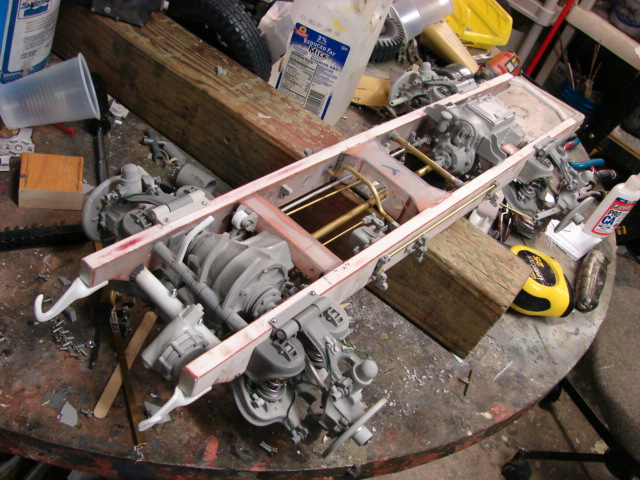
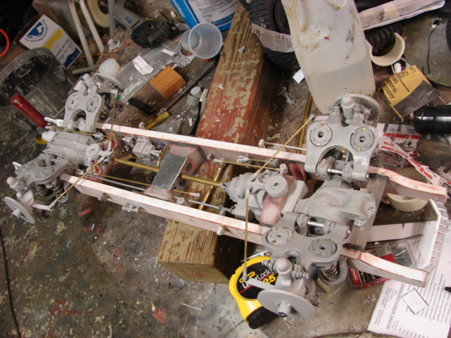
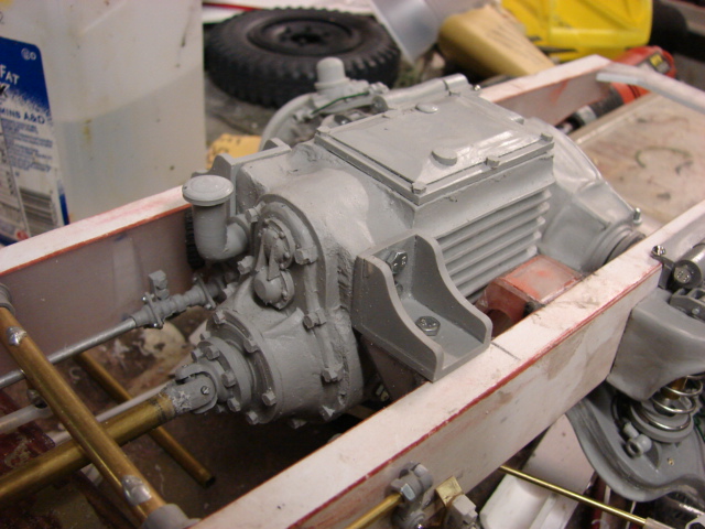
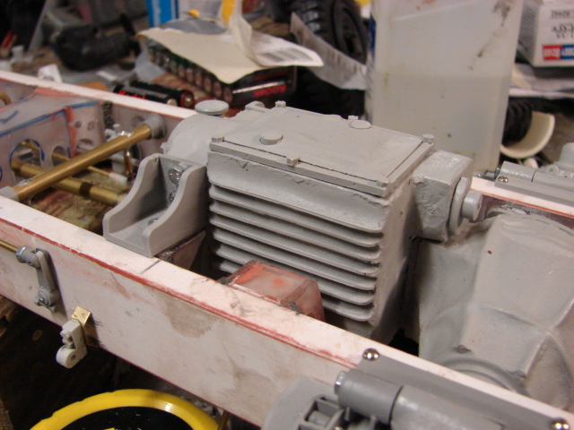
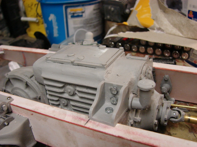
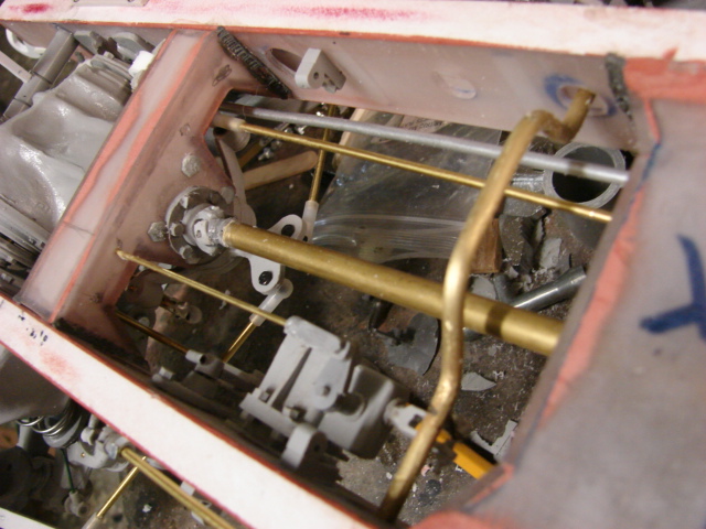
The transmission casing has been installed, and added to the catalog. http://www.eastcoastarmory.com/222.htm
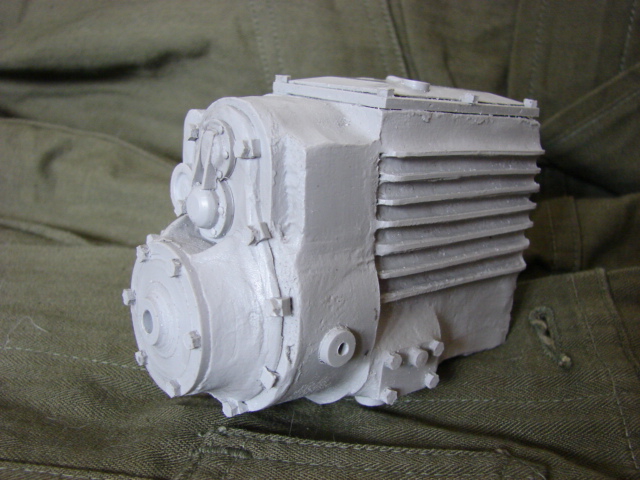
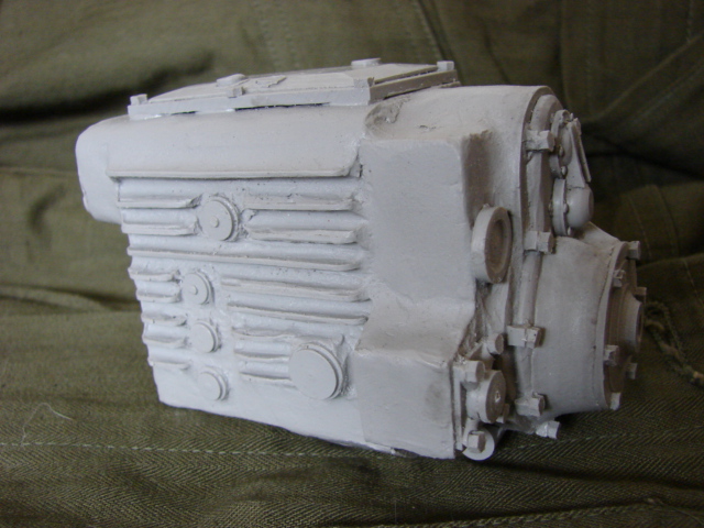
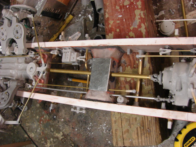
the transmission connects to the front differential via a long drive shaft that runs through the length if the chassis.
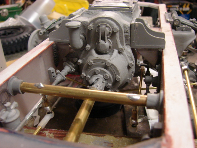
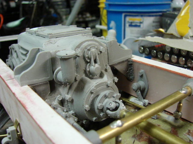
The smaller rod that runs along the the drive shaft is the shifter. This rod connects to the stick shift and is what allows you to change through the gears.
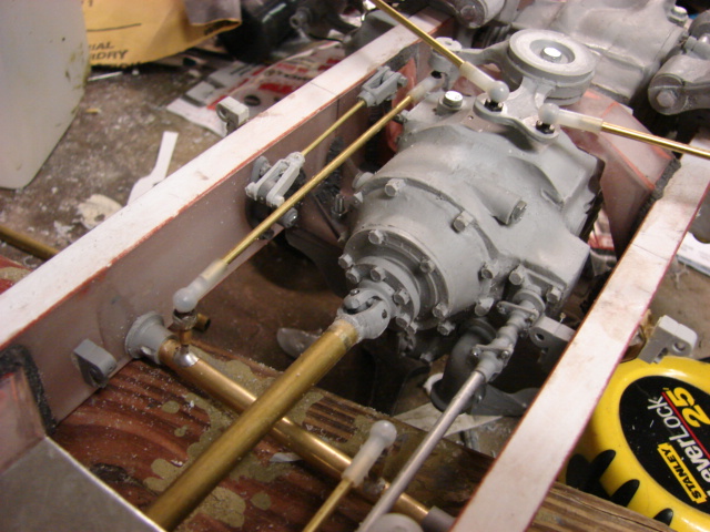
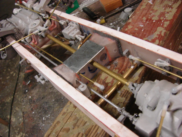
The armored car's breaking system was also partially added. The 222 had both a hand break and regular driving break. Once the chassis get's it's base coat the rest of the cables will be mounted. Because of all of the equipment on the interior of the chassis, the breaking system must run through the exterior of the chassis frame
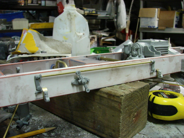
The hand break is located in the transmission housing, and is controlled via a hand lever in the driver's station. The hand break connections are done via a solid connection.
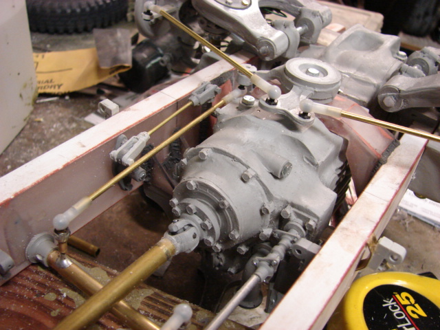
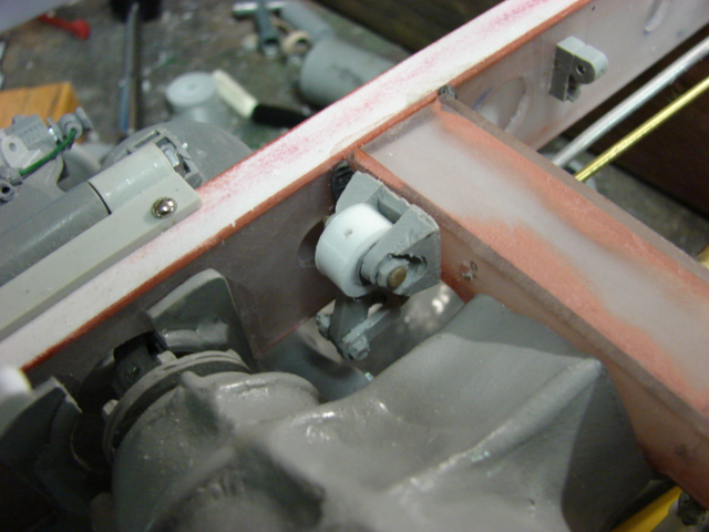
The break pedal, Accelerator, and the clutch are all mounted together on a bar. This bar is located below the floor boards.
All of the pedals, stick shift, and hand break lever will be added after the installation of the floor boards.


For the breaking system the pedal is connected to a hydraulic box which in turn is connected to a horizontal bar. This horizontal bar is connected to the pulley cable system...which is then connects to the wheels.
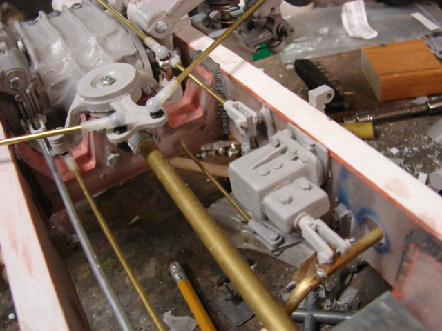
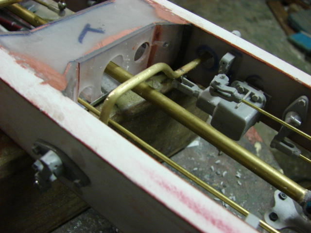
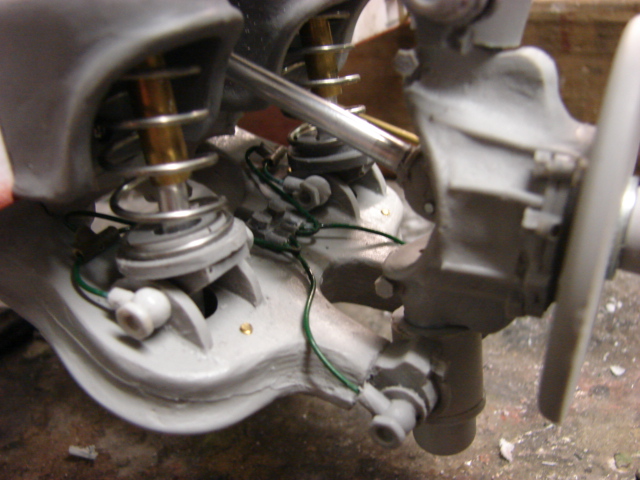
Another hydraulic system that the 222 had and was mounted was the lubrication system. The 222's suspension has many lube points and rather than having a zerk fitting for all of these points the 222 had plumbing lines that connected to all of these locations. This way all of the joints would the needed lubrication.
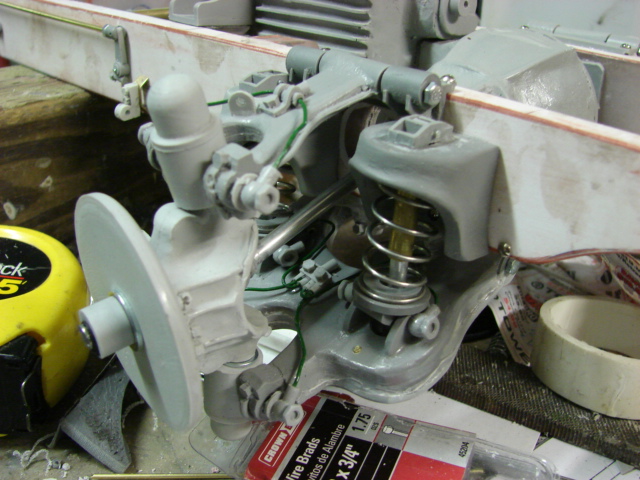
All of these lines would Y off to their needed locations.
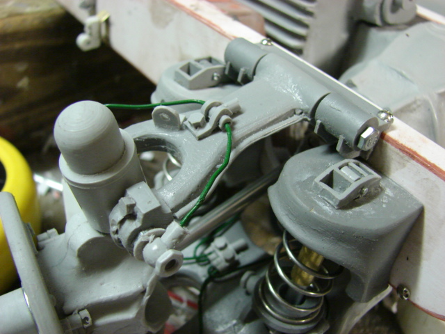
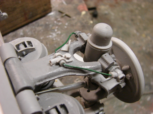
For the bottom set of swing arms the plumbing would diverge into 4 channels. The two would go to the pivot points on the bottom swing arm, while the other two would separate again and would connect to the spring level shelf. Both shelves received these lines.
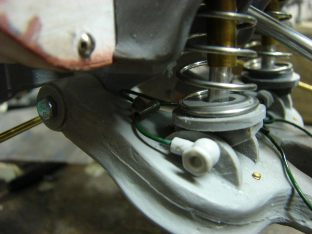
The oil reservoir is found behind the main bulkhead
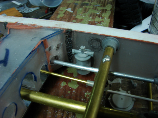
On the lower chassis main bulkhead I added a steel plate which is found on the real vehicle. The plate covers the gap that is cut into the bulkhead for the driveshaft, and other connection rods. This plate prevents foreign objects from entering the space and causing problems.

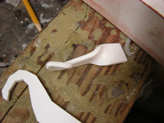
On the front of the vehicle I mounted the front tow shackles
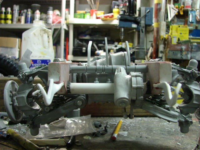
The tow hooks were the stock kits ones, and were reworked. The stock kit hexagonal appearance was smoothed out via a dremel. After the shape was rounded off I heated the hooks with a heat gun, and bent the hooks to shape.

Once the hooks were bent they were bolted to the chassis.
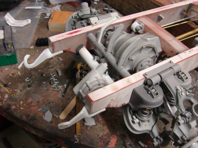
The rear frame bulk head / engine mount was added. The bulkhead is all fabricated out of lexan, and styrene
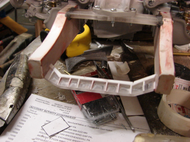
Like the break lines I will be adding the control lines and the rest of the lube plumbing after the chassis is painted.

The break lines and the lube lines set will also be added to the catalog once the lines are completed.

A youtube video was created showing the progress
http://youtu.be/96fZa3cDURY

More pics were posted to the ECA facebook page
http://www.facebook.com/EastCoastArmory

I will now be assembling the upper hull. Once the upper hull is assembled I can then focus on the interior and engine detailing. More to come!

  • Member since
    April 2005
Posted by armourguy on Sunday, February 17, 2013 10:41 AM

Thanks guys, the last of the suspension components have been added and the suspension is now complete.

Like the differentials the steering collars were designed to have their u joints functional. This was key to having both the suspension go up and down, but to also steer.

For the steering connections I used brass rods along with metal and nylon ball linkages. the ball and socket linkages were also used on the real vehicle

The steering on this vehicle is very unique. The 222 featured four wheel steering. Unlike the Puma which had two steering wheels the 222 wheels were all controlled by a singe driver.

One unique feature is the steering distribution bar. This bar connects the front steering with the rear steering.

Basically this bar inverts the throw of the rear wheels, so when the front wheels are turned the rear wheels turn in the opposite direction, which will give you tighter turns.

In addition to the four wheel steering I also tooled up the 222 steering column.

The steering column is designed to be able to pivot along with the suspension/

Both the steering column and the suspension have been added to the part listings East Coast Armory -- 1/6th scaleSDKFZ 222 armored car detail upgrades.

In addition to mounting the suspension I also worked on the fitting of the 222's wheels.

For the wheels I used the resin early 222 wheels from Panzerwerk.

The panzerwerk wheels are simply excellent!

To mount the panzerwerk wheels to the suspension I modified the Panzerwerk brake drum to accept a new machined bushing. The bushing is retained to the suspension via a machined steel rod and a spring washer.

The system allows the wheels to spin freely, but prevents them from falling off

The wheels will be mounted and assembled after both the wheels and the suspension are fully painted.

A youtube video update was created which shows the suspension's function more in detail. 1/6th scale German SDKFZ 222 armored car project video #4 (working suspension complete) - YouTube

more images were also added to the ECA facebook page, http://www.facebook.com/EastCoastArmory

With the suspension out of the way I can now focus on the transmission . I also already have the lubrication, and braking system master complete. Once complete they will be added to the model and the product line. More progress to follow, stay tuned!

  • Member since
    December 2002
  • From: NYC, USA
Posted by waikong on Tuesday, February 5, 2013 1:17 PM

holy cow that looks great!

  • Member since
    May 2005
  • From: Dublin Rep Of Ireland
Posted by terry35 on Sunday, February 3, 2013 3:10 PM
Amazing work, as always a pleasure to look at.

  • Member since
    April 2005
Posted by armourguy on Sunday, February 3, 2013 1:59 PM

Thanks guys, I'm not into RC airplanes but they are cool...especially if you are good at flying.

it's been a while since I had any progress...but I have been working on the model's functional suspension.

I have completed the swing arms and mounted them to the vehicle.

Unlike the Puma which uses leaf springs the 222 suspension was easier to make functional because it uses coil springs. The 222's suspension is also simpler to mount because it uses four suspension clusters as opposed to the eight of the puma.

While tooling up the 222 suspension parts I used lots of tricks and improvements that I learned from tooling up the Pumas suspension that I did a few years ago

The 222's suspension were comprised of four clusters which contained the swing arms, springs and shock absorbers.

All of the swing arm and spring mounts are mounted to the chassis frame via fasteners and glue. This was done for the extra strength needed for load bearing from the springs.

The two coil springs are what keeps the suspension from sagging, and to keep the springs aligned with the chassis spring mounts they themselves are mounted on swivel plates. The swivel plates rotate on the lower swing arm. This way the springs stay at a 90 degree angle no matter how the swing arm dips or rotates. I don't believe that this detail / function was added to any other 222 model.

connecting the whole unit together are two smaller shock absorbers that are mounted to the bottom swing arm. These shocks run through the center of the swivel plate, through the center of the springs and are mounted to the top of the chassis spring mount.

the shocks prevent the bottom swing arm from over swinging and keep it contained to the cluster. To secure the shocks to the bottom of the swing arm they are held in place by a retaining cap which is bolted to the bottom portion of the swing arm. the resin retaining cap uses two brass hex bolts to secure the cap to the arm, and the molded in hex bolts are just for detail.

more pics were added to the facebook page http://www.facebook.com/EastCoastArmory?fref=ts

With the swing arms out of the way I can now focus on the steering and wheel hubs. Once complete I will post an update as well as a youtube video. More to follow!

  • Member since
    March 2003
  • From: Western North Carolina
Posted by Tojo72 on Tuesday, January 22, 2013 5:46 AM

wow that is going to be one impressive project.

  • Member since
    January 2007
Posted by the doog on Monday, January 21, 2013 10:25 PM

Holy crow! Talk about an ambitious project! Looks like you're tackling it with vigor though!

  • Member since
    July 2011
  • From: Pittsfield, IL USA
Posted by novembergray on Monday, January 21, 2013 9:44 PM

Stop teasing us. Let's see the bottle of glue that came with it!  Big Smile

I can't wait to see it finished.

Dunno if you're into aircraft too or not but I was checking out this 1/5 scale stuka today  http://www.rlm.at/cont/gal17_e.htm

Joe

It's not about how fast you get there or even where you're going. It's whether you enjoy the ride.

  • Member since
    April 2005
Posted by armourguy on Monday, January 21, 2013 10:01 AM

Thanks guys, It's been awhile since my last post but I have been working on tooling up the model's suspension. I have completed the model's differentials and  have added them to the newly created SDKFZ 222 product line. www.eastcoastarmory.com/222.htm

I made both the front and rear differentials. I made the spindles spin and the universal joints functional as well. This was done so when the functional suspension is made the drive shafts will pivot all together.

A youtube video was created describing how they mount to the hull, and the way they connect to the transmission and drive train.

I'm now working on tooling up the swing arms. I already ordered some nice wheels from panzerwerk. Once the swing arms are done I will post another update. More to come!

  • Member since
    January 2010
  • From: St. Louis
Posted by Shawn M. on Wednesday, January 9, 2013 12:39 PM

great job on the chassis!

I love the smell of plastic in the morning

  • Member since
    February 2007
  • From: Brunswick, Ohio
Posted by Buckeye on Wednesday, January 9, 2013 11:25 AM

Have never seen any of these before.  Looks like quite a project!

Mike

JOIN OUR COMMUNITY!

Our community is FREE to join. To participate you must either login or register for an account.

SEARCH FORUMS
FREE NEWSLETTER
By signing up you may also receive reader surveys and occasional special offers. We do not sell, rent or trade our email lists. View our Privacy Policy.