SEARCH FINESCALE.COM

Enter keywords or a search phrase below:

Meng FT-17 French Light Tank Riveted Turret

21556 views
137 replies
1 rating 2 rating 3 rating 4 rating 5 rating
  • Member since
    January 2013
Posted by jibber on Monday, October 13, 2014 9:25 AM

Wow nice Bill, I thought those track pieces may have been a bit of a problem, it looks like they lay in there real nice. Unlike others, you surely couldn't go 31 or 33. As usual, nice and clean.

  • Member since
    March 2012
  • From: Corpus Christi, Tx
Posted by mustang1989 on Monday, October 13, 2014 3:24 AM

This is coming together fast Bill. Looks good from here.


 Forum | Modelers Social Club Forum (proboards.com) 

  • Member since
    August 2007
  • From: back country of SO-CAL, at the birth place of Naval Aviation
Posted by DUSTER on Monday, October 13, 2014 12:25 AM

DANG you can just hear the clank-ity, clank, Good work nice to see it coming together Yes.

Steve

Building the perfect model---just not quite yet  Confused

  • Member since
    July 2004
  • From: Texas
Posted by wbill76 on Saturday, October 11, 2014 4:45 PM

Returning to the hull details, I went all the way back to Step 3 and added the details required for the left side of the hull. The kit includes a metal strut and spring for the front part of the suspension and the key to getting this in at the right height is the spring itself and the 'cap' styrene part that sits on top, D11. D11 doesn't sit snugly on top of the strut, so I glued the strut and spring into the housing with CA first and then added D11 to the top after to ensure it lined up correctly with the suspension module and wouldn't cause any fit issues along the way. Tow hooks and large box and rack were also added to round things out.

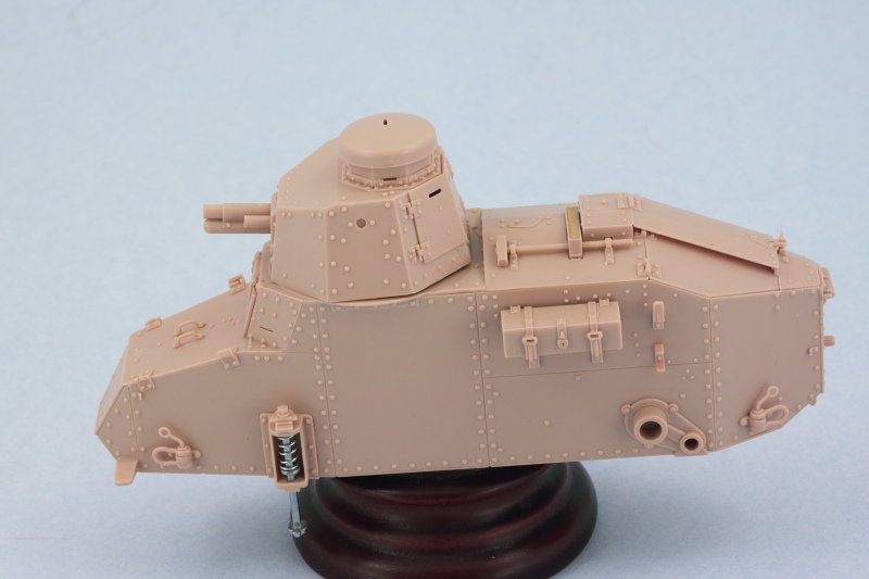
Process was repeated for the right side in Step 5 but I left off the exhaust muffler for the time being as that will be detailed and installed after painting.

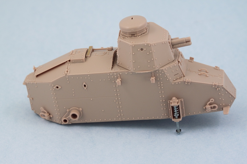
And just to be sure that 'stumpy' here would sit properly with the suspension modules in place, a dry-fit was in order! The test fit shows that when the time comes to glue the modules in place I'm going to have to be a little careful that they sit level as there's a slight tendency for the top to want to bow in slightly since there really isn't anything on the top side to prevent that by way of connection points.

The next item of interest were the tracks which are dealt with in Step 12. The kit provides click-able individual tracks that will produce workable tracks of 32 links per side. I found in the assembly process though that I had to keep a sharp eye out for tiny amounts of flash around the hinge points as if those weren't caught the links would fit together almost rigidly or require too much force that could snap off the small pins. Fortunately the kit provides plenty of extra links so it wasn't a huge deal when a couple got sacrificed in this learning step.

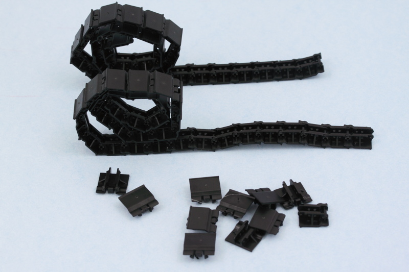
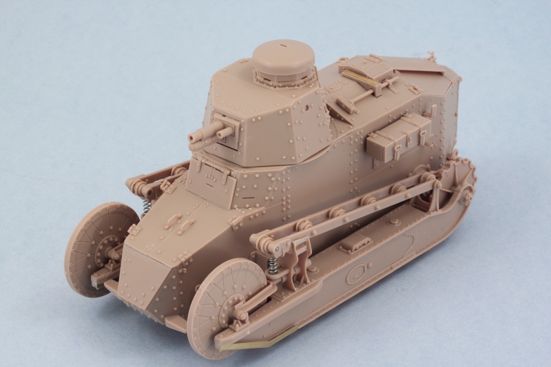
A quick test fit with the suspension modules showed everything playing nice and 32 links working out perfectly. Connecting up the ends of the runs once the tracks have been painted and weathered may be a little challenging...I may just remove one or both of the pins on those final links and just rely on gluing the links together to secure the runs, have to see when the time comes.

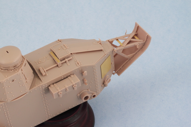
The last remaining area needing attention was the rear hull and the un-ditching tail covered in Step 11. I'm not 100% sure, but I think the PE placards (parts W5) should be placed only if you're doing the American WW1 version of this kit so be mindful of that as the instructions don't make any kind of distinction there.  Since I am doing the American version, these were installed with Gator Grip glue so I could have some work time to get them properly positioned/straight relative to the areas they install into. The folded up tarp that installs over the X brace on the tail is left off for now and will be added after painting.

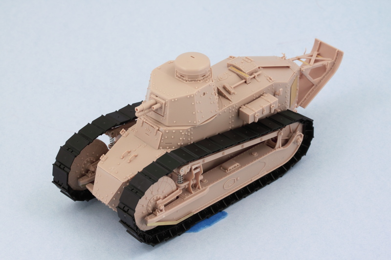
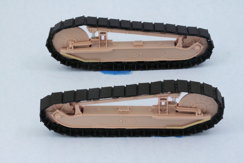
Just to satisfy my curiosity, I did a full mock-up with the suspension elements and tracks and I'm now 100% convinced that painting the suspension separately and installing after is the right way to go on this little guy.

  • Member since
    January 2013
Posted by jibber on Thursday, October 9, 2014 5:06 PM

I agree with you on painting them separate and masking off those connection points is always a good thing. Thats really going to be a nice model, Meng goes way beyond the norm with their detail, I've just found their plastic a little "soft" but I plan on building more of them, maybe their D9R. Thanks Bill.

Terry

  • Member since
    July 2004
  • From: Texas
Posted by wbill76 on Thursday, October 9, 2014 11:59 AM
Sackgasse

Hi Mr. Bill,

Never thought that I would want to build a French AFV until now :)

Interesting trick with the live springs, I think Bronco has done something similar on their SdKfz. 221.

Happy Modelling!

Zack

I hear you there Zack! Something about this early/industrialized approach to the design and all those rivets I imagine creates a special appeal. Smile I'm glad Meng supplied real springs for the suspension, there's really no other way to accurately model that IMHO.
  • Member since
    July 2004
  • From: Texas
Posted by wbill76 on Thursday, October 9, 2014 11:57 AM

Thanks Mustang! There's 45 different parts that go into each side of those suspension elements, so a lot going on with them for sure. Beer

  • Member since
    May 2014
Posted by Sackgasse on Thursday, October 9, 2014 11:56 AM

Hi Mr. Bill,

Never thought that I would want to build a French AFV until now :)

Interesting trick with the live springs, I think Bronco has done something similar on their SdKfz. 221.

Happy Modelling!

Zack

Happy Modeling! Cool

  • Member since
    March 2012
  • From: Corpus Christi, Tx
Posted by mustang1989 on Thursday, October 9, 2014 11:15 AM

Now that's some in depth suspension parts Bill. Cant wait to see em painted up and weathered!


 Forum | Modelers Social Club Forum (proboards.com) 

  • Member since
    July 2004
  • From: Texas
Posted by wbill76 on Thursday, October 9, 2014 10:16 AM

Steve

can't argue with you there! Big Smile

Terry

it's definitely interesting to see how these early tank designs tackled different challenges particularly in the suspension department. This particular arrangement almost has a Rube Goldberg feel to it IMHO! Wink

I am thinking that it will be better to paint the suspension as separate 'modules' from the hull and then attach simply because of all the tight corners and spaces. The suspension attaches to the hull at the rear via some solid connection points but at the front only has the struts for the main suspension spring to hold it in place, so those would probably have to be masked off so they have a clean attachment point since the struts are metal.

  • Member since
    January 2013
Posted by jibber on Thursday, October 9, 2014 8:10 AM

This is great stuff, I'm planning mine for December and this is my "GoTo" tutorial for sure. Again this is a great little vehicle and maybe the coolest suspension ever. I still love those large rivets.

Bill do you think it may be better to paint ahead the suspension parts, at least a primer, or would it make it troublesome for assembly?

Terry

  • Member since
    July 2003
  • From: On my kitchen counter top somewhere in North Carolina.
Posted by disastermaster on Wednesday, October 8, 2014 10:18 PM

Well, this should be interesting....... http://www.animateit.net/data/media/august2009/th_zombie3.gif

Sherman-Jumbo-1945

"I never know what to expect here anymore."


  • Member since
    July 2004
  • From: Texas
Posted by wbill76 on Wednesday, October 8, 2014 7:01 PM

Made some more progress on the little FT-17, this time in the suspension department. I decided to build up the suspension units one side at a time since the elements that you construct in Step 8 are 'handed' between the left and right side and I didn't want to cause any confusion there. I started with the A and B components needed for the left side and also assembled the return roller frame. Lots of care is needed when gluing the frame halves together so that the rollers remain free to rotate. Adding the metal pin and frame supports at the front is also a little challenging but works out in the end with a little patience. When assembling the road wheel elements, I found it easiest to assemble the frame halves and wheels together first, then add the top support arm portion before the glue had set up. This way you could flex the tops open to accept the pins without having the whole thing come apart in the process. The biggest time-consuming element in this step is cleaning up the two sprue connection points per road wheel and return roller as they have very delicate rims that intersect with the connection points.

Step 9 assembles the full suspension unit using the components from the previous step. It's possible to assemble it and leave the suspension fully workable if you use the top part of the unit to help hold the sides together. Again, a very tricky assembly process that will leave you wishing you had another hand to help out but the end result produces a very nicely detailed assembly. Once the top and sides were firmly together, I added the support base for the return roller frame and used the kit-supplied steel spring and some CA glue to ensure it sat at the right height and angle to match up with the large idler.

Once I'd figured out the little tricks and traps by doing the first unit, the second one for the right side took only half as long to pull it together.

Given how complex this all is and how the suspension relates to the hull, I'm seriously considering leaving them separate for painting to make it easier to get everything covered and also make life simpler in terms of applying a camo pattern. Next up are the exterior details for the hull!

  • Member since
    July 2004
  • From: Texas
Posted by wbill76 on Saturday, October 4, 2014 9:54 AM

Thanks Mustang! Wink

Bish

thanks as well! Happy to pass along the idea, there's really only one way all the plates can line up together but when they are sitting on the bench together waiting for assembly this just keeps it simpler especially once you start adding glue to the mix. Beer
  • Member since
    December 2002
  • From: Bury St Edmunds, Suffolk, England
Posted by Bish on Saturday, October 4, 2014 9:12 AM

Looking really nice Bill. And a great idea to mark those turret panels, that would be so easy to get wrong if your not careful. A great tip.

I am a Norfolk man and i glory in being so


On the bench: Airfix 1/72nd Harrier GR.3/Fujimi 1/72nd Ju 87D-3

  • Member since
    March 2012
  • From: Corpus Christi, Tx
Posted by mustang1989 on Saturday, October 4, 2014 7:16 AM

Looks like its coming together nicely Bill.


 Forum | Modelers Social Club Forum (proboards.com) 

  • Member since
    July 2004
  • From: Texas
Posted by wbill76 on Friday, October 3, 2014 4:23 PM

Made some great progress on this little guy in the turret department. Steps 16 and 17 cover the assembly and it's important to note that the base of the turret is an octagonal ring with notches for tabs at the bottoms of each of the plates. You can start wherever you want, but once you commit to the position of the front plate with the gun, you need to place all the other plates as the instructions point out. In anticipation of that, I removed each of the panels from the sprue, cleaned them up, and marked their part number on the inside face so I didn't accidentally place a plate in the wrong spot.

I opted for regular glue on the bases of the plates so they had a good grip, placed the front plate and gun first, then added the plates to either side, and so on until I had all the plates in position. I deliberately did not apply any glue to the areas where the plates met each other though until I was ready to install the turret roof plate. This made it possible for me to use the roof plate to help ensure all the side plates leaned in at the right angle and matched up as needed. I was impressed with the fit/engineering of all these parts...they all lined up nicely and only needed some slight finger pressure in a couple of spots to help the liquid glue grip and seal up the plate joins.

With all the plates in place, I added the rear turret hatches in the closed position. Then the three part cupola came next to round out things for the turret.

The turret base ring fits snugly into the hull roof opening, a nice friction fit that still allows the turret to rotate, so I'll have to be mindful of that when painting to ensure it stays that way.

Next up will be tackling the suspension components, lots of small parts there so will take my time there as well.

  • Member since
    July 2004
  • From: Texas
Posted by wbill76 on Thursday, October 2, 2014 8:04 PM

Thanks Lee! Glad to have you along and good to hear you find the blogs helpful. Always happy to share the good, bad, or ugly when it comes to a build. Beer Wink

  • Member since
    January 2003
  • From: Washington State
Posted by leemitcheltree on Thursday, October 2, 2014 7:28 PM

WBill....I like your logical steps and the way you attack the small problems you've found.

Additionally - one thing that often really lets down a WIP build is the pics.

The use of the that wooden mount, and your care with taking the pics is excellent - possibly running only a close second to ChukW.

Keep up the great work, mate - I'm looking forward (a great deal) to seeing this one progress.

Thanks for your efforts to edumacate us all as you move forward.  Good deal!

This is what this website is all about - people like you sharing.  Awesome.

Cheers, LeeTree
Remember, Safety Fast!!!

  • Member since
    July 2004
  • From: Texas
Posted by wbill76 on Wednesday, October 1, 2014 3:05 PM

That's true CTD! Meng does offer the full interior version in a different FT-17 kit and if I had that one, it would've been worth it. In this one there's so much that's not there that closing it up made life a lot easier.

  • Member since
    January 2010
Posted by CrashTestDummy on Wednesday, October 1, 2014 12:36 PM

wbill76

J-M

glad to have you along for the ride! Wink

Mustang

I can understand why Meng went this route since that's how the actual turret was constructed...a series of octagonal riveted plates on a frame. It also allows them to mold detail on both sides of the plates for greater realism on the interior if you choose to have the rear turret hatch open as well. It does make for a more intricate assembly though, no question about that! Smile

Yeah, but on the actual tank, I'm sure they had templates, and stabilizing brackets to help with assembly. 

Sad to see you're not opening it up, but I understand fully.  It'll speed up the assembly, and cut down on the 'how much additional detail do I add to this one?' decisions.  Wink

G. Beaird,

Pearland, Texas

  • Member since
    January 2013
Posted by jibber on Tuesday, September 30, 2014 7:09 PM

Thanks Bill.

  • Member since
    July 2004
  • From: Texas
Posted by wbill76 on Tuesday, September 30, 2014 11:55 AM

Works for me Terry! No harm in following along to see how this one builds up and avoiding any pitfalls that might pop. Happy to be the guinea pig. Big Smile I haven't yet decided if I'm going to use the base or not...it's kind of a 'dio in a box' arrangement which I think is neat but may not fit inside my available display cabinet space, so that may end up being the ultimate deciding factor on that front.

  • Member since
    January 2013
Posted by jibber on Monday, September 29, 2014 2:05 PM

Bill I was going to start my FT-17 for the next WWI GB but I think I'll ride this one out and pickup some tips along the way, I hope you don't mind. Its a little like watching another golfer putting the same line and you sneak a peek to see what its going to do, anyway are you going to use the provided base? I looked at it, and just by itself it should make a very nice presentation. Terry

  • Member since
    July 2004
  • From: Texas
Posted by wbill76 on Monday, September 29, 2014 1:20 PM

Bish

Glad to have you along! This one will serve to scratch my WWI itch just about right I think! Wink

  • Member since
    December 2002
  • From: Bury St Edmunds, Suffolk, England
Posted by Bish on Monday, September 29, 2014 12:31 PM

Damn, missed the start of this one. But then its hard to keep up with your builds. Nice subject, its good to see something different, even if it is French Zip it!

I am a Norfolk man and i glory in being so


On the bench: Airfix 1/72nd Harrier GR.3/Fujimi 1/72nd Ju 87D-3

  • Member since
    July 2004
  • From: Texas
Posted by wbill76 on Monday, September 29, 2014 11:58 AM

J-M

glad to have you along for the ride! Wink

Mustang

I can understand why Meng went this route since that's how the actual turret was constructed...a series of octagonal riveted plates on a frame. It also allows them to mold detail on both sides of the plates for greater realism on the interior if you choose to have the rear turret hatch open as well. It does make for a more intricate assembly though, no question about that! Smile
  • Member since
    March 2012
  • From: Corpus Christi, Tx
Posted by mustang1989 on Monday, September 29, 2014 5:13 AM

wbill76
Since the turret assembles as a series of plates onto an octagonal base, that's going to require some careful attention to get all the plates together and lined up between the roof and base

That sounds like a PIA! ..............and intense!


 Forum | Modelers Social Club Forum (proboards.com) 

  • Member since
    August 2006
  • From: Oromocto, Canada
Posted by Gun Tech on Sunday, September 28, 2014 9:54 PM

Nice!  

I wanted to see one built up for a little while now.

I'll gladly follow!

Jean-Michel    "Arte et Marte"

  • Member since
    July 2004
  • From: Texas
Posted by wbill76 on Sunday, September 28, 2014 2:49 PM

After some back and forth I decided ultimately to go ahead and button up this little guy and not display the driver's hatches open. So with that decided, I set about assembling the hull. Since it's all separate panels, I used regular glue on the hull sides so they could have some stability and then followed that up with careful applications of liquid glue where needed along the bottom edges.

Then I added the roof plate next so I could use it to get the hull sides lined up square and the small driver's area side plates lined up with the view port hatch hinge and the top edges of the roof plate. This all requires some careful use of finger pressure and glue as the areas involved are tiny and rubber bands or clamps can't do the job. Then I added the angled top plate for the nose and the driver's access hatches since all three need to line up just so with each other to avoid issues or gaps. Last but not least, I added the driver's visor in the closed position.

That got a chance to set up nice and solid overnight and attention turned to the engine deck area under Step 6. It's important to note (as the instructions do) that the sledgehammer is trapped in place by the little vent cover, B9, so that means it will have to be detailed in place later on. To help make that easier, I didn't glue the sledgehammer down, just placed it and am allowing B9 to hold it in place for now. In Step 7, the instructions would have you place part B11 and then add the engine bay hatches in Step 14. I found it easier to add them all together at the same time as B11 needs to be lined up very precisely in relation to the hatches for everything to play nice with each other here. This isn't a kit flaw or an engineering issue, quite the contrary...the engineering is very well done for these parts but since the vehicle itself is so small, fractions of a mm do matter in getting everything lined up correctly with all the plates/parts involved.

In preparation for working on the turret, I opted for the 37mm cannon version in Step 15. I assembled the gun as directed and used a drill bit to open up the cannon muzzle a bit more. The molding on the end of my barrel wasn't perfect, so some careful sanding and trimming was needed to get it into shape. I also installed it into the turret faceplate so that its all one module now and ready to go into the turret.

Since the turret assembles as a series of plates onto an octagonal base, that's going to require some careful attention to get all the plates together and lined up between the roof and base, so that will be what's on deck for the next round of effort

JOIN OUR COMMUNITY!

Our community is FREE to join. To participate you must either login or register for an account.

SEARCH FORUMS
FREE NEWSLETTER
By signing up you may also receive reader surveys and occasional special offers. We do not sell, rent or trade our email lists. View our Privacy Policy.