SEARCH FINESCALE.COM

Enter keywords or a search phrase below:

Tamiya 1/35 SU-76M--Complete 04/10/16

8769 views
101 replies
1 rating 2 rating 3 rating 4 rating 5 rating
  • Member since
    December 2002
  • From: Bury St Edmunds, Suffolk, England
Posted by Bish on Wednesday, March 30, 2016 1:25 PM

Great work build and really nicley done WiP. I agree about how this is engineered, looks really well done. Is that barrel one piece.

I am a Norfolk man and i glory in being so


On the bench: Airfix 1/72nd Harrier GR.3/Fujimi 1/72nd Ju 87D-3

  • Member since
    November 2009
  • From: SW Virginia
Posted by Gamera on Wednesday, March 30, 2016 2:41 PM

Nice work there on the gun and mount. I have a feeling it probably didn't fit anywhere near as well on the older non-Tamiya versions. 

"I dream in fire but work in clay." -Arthur Machen


  • Member since
    July 2004
  • From: Texas
Posted by wbill76 on Wednesday, March 30, 2016 4:39 PM

Bish

, yes, the main gun barrel is provided as one piece. Wink 

Gamera

, thanks as well! You may be right, I haven't built any of the other models out there of this particular vehicle so can't say one way or the other. Beer 
  • Member since
    July 2004
  • From: Texas
Posted by wbill76 on Thursday, March 31, 2016 7:05 PM

I spent the day working mostly on the gun's details so I could get it installed permanently into the compartment. That involved working on several different areas including the gunner's sight. The kit part has solid faces all around, so I used a micro-drill to open up both the eyepiece portion and the top sight opening itself. I also used the same approach as with the fighting compartment to weather the rear parts of the gun and mount to get them to match up. 


Detail work also included getting the breech block painted and installed and the bare metal surfaces on the recoil sled picked out. 


With the gun now detailed, I installed it permanently into position. I made sure to firmly press the gun all the way down into the polycap's mount since it needs to be down far enough not to cause any interference with the top mantlet piece that locks it all in place. A little bit of liquid glue around the triangle portions of the mantlet piece and some careful gentle finger pressure got it all joined together. 


Once I had that done, I also worked on detailing the 3 periscopes that go into the fighting compartment. The kit parts are molded in one piece in the green styrene, not clear, and had an ejector mark on one side that had to be dealt with. To simulate the clear faces, I applied some enamel Steel followed by a dose of Tamiya Clear Smoke. Tamiya does include a clear sprue in the kit (oddly enough, only 1 of the 8 parts on that sprue actually gets used, the headlight lens) but I don't think it's really designed for this kit per se. The clue is that the sprue includes 4 sets of goggles that have no possible use on this vehicle or its figures, so perhaps they just repurposed it from another kit or set? Either way, it wouldn't have been hard to have clear periscopes for a little more detail potential since they are so prominent in the fighting compartment. 


I also started on the hull details by working on the side air intake. This is molded solid with a grill pattern so I used a thinned wash of MM enamel Gunmetal to darken up the spaces in the mesh pattern. A careful drybrushing of the 50/50 OD/Russian Armor Green with a small square tip blender brush brought the mesh pattern back out so it would have some depth (or the best possible simulation of it at any rate) to its look. 


Tools and the exhausts are next! 

  • Member since
    October 2015
Posted by Modelrob on Friday, April 1, 2016 5:08 AM

The mesh came out looking good. The build is coming along nicely.

Robert

  • Member since
    July 2004
  • From: Texas
Posted by wbill76 on Friday, April 1, 2016 11:50 AM

Thanks Rob! Sometimes the old trick book has to be hauled out even on new releases like this one. Wink Beer 

  • Member since
    September 2006
  • From: Central Texas
Posted by NucMedTech on Friday, April 1, 2016 3:47 PM

Bill this is coming out great. Kind of caught me by surprise as it is not german, lol. Am I correct in assuming this is out the box without any am parts? If so, it shows the quality of the molds, everything looks sharp and crisp.

-StephenCowboy 

Most barriers to your successes are man made. And most often you are the man who made them. -Frank Tyger

  • Member since
    July 2004
  • From: Texas
Posted by wbill76 on Friday, April 1, 2016 3:57 PM

NucMedTech

Bill this is coming out great. Kind of caught me by surprise as it is not german, lol. Am I correct in assuming this is out the box without any am parts? If so, it shows the quality of the molds, everything looks sharp and crisp.

-StephenCowboy 


Thanks Stephen! You are correct, I'm building this one OOB with no AM added. I have been following the 'IPMS Rules' for a true OOB (it's ok to remove stuff like drilling out or thinning stuff down) effort so people can see how the kit comes together. I agree with you on the quality of the molding, Tamiya doesn't disappoint in that regard. Beer You're right about it being something 'a little different' but then variety is important to prevent burnout and broaden your horizons from time to time. Big Smile 

  • Member since
    July 2003
  • From: On my kitchen counter top somewhere in North Carolina.
Posted by disastermaster on Friday, April 1, 2016 4:21 PM

the doog

Cool beans, Bill! It's all looking great, as usual!

Playing on the radio right now.... "HEY LA, HEY LA, MY BOYFRIEND'S BACK..."! Big Smile

(hey man, it's the 21st century, don't freak out, lol)

           Yay........ http://www.wineonthekeyboard.com/wp-includes/images/smilies/AngelSmilie.gif http://www.clicksmilies.com/s1106/engel/angel-smiley-023.gifhttp://www.4smileys.com/smileys/angel-smileys/angel_smiley007.gif  "The Angels"

                             Good stuff!

Sherman-Jumbo-1945

"I was so much older then, I'm younger than that now"


  • Member since
    July 2003
  • From: On my kitchen counter top somewhere in North Carolina.
Posted by disastermaster on Friday, April 1, 2016 4:21 PM

Good to see the "Podium" back in action.

                          http://www.melaniewiscount.com/mwiscount_cpopyright_fairuse_WQ/graphics/gavel_front_md_clr.gif

Sherman-Jumbo-1945

"I was so much older then, I'm younger than that now"


  • Member since
    July 2004
  • From: Texas
Posted by wbill76 on Friday, April 1, 2016 5:59 PM

Thanks Steve! The podium certainly gets its share of a workout. Wink 

  • Member since
    July 2004
  • From: Texas
Posted by wbill76 on Friday, April 1, 2016 6:19 PM

The details were the featured item on the menu today with the bulk of the focus on getting the tools detailed and ready for installation. Most of these install on the flat deck in front of the fighting compartment while the gun cleaning rods go under the left side overhang and behind the fender storage boxes. That's why those rods are called out in Step 15 before the fender installation, there's no real easy way to get them in place unless you leave the fenders removable like I've done. The rest of the tools are scattered around in the instructions in Steps 23-25. They were removed from the sprue, cleaned up, and detailed by hand. The only minor annoyance was Tamiya's decision to integrate the two spare links and the jack block into a single piece. It definitely made detailing those two very different elements an exercise in patience! 


I used MM Non-Buffing Metalizer Gunmetal as the base for all the metal parts, lightly dry brushed some enamel Steel, then dusted them with some black artist pastels to blend it all together. For the wood areas, I applied a base coat of 50/50 Afrika Grunbraun/Light Gray since it has a nice 'wood' tone, then applied a light wash of enamel Leather followed by some burnt umber artist pastels to get the look I wanted. With all that done, the tools were installed in place. 


I did make some minor modifications to the shovel by sanding down its edges to get them more in-scale and also drilled out the exposed end of the gun cleaning rod for a little more detail. 


Next up were the exhausts. The two halves were assembled as directed in Step 21 and their join seam sanded down after the glue had set. I applied a base coat of MM non-buffing Metalizer Gunmetal to the bare plastic and then followed that up with multiple applications of a thinned Leather wash to build up some tonal variations. Some burnt orange artist pastels helped here as well and black artist pastels were added to the exhaust tips for some soot accumulation. The exhaust tips themselves were molded solid, so some quick work with a micro drill opened them up. I had to sacrifice one of the t-shaped retaining clamps for the exhausts to the carpet monster, but a quick bit of scratch building using strip styrene and rod gave me an adequate replacement. 


I had kept the two different exhaust pipes separate throughout the painting process and only joined them up once I was ready to install them in place. The key is to place the pipes in position first, then feed their long d-shaped tabs into the exhaust cylinders so that everything lines up correctly. Only then did I apply some liquid glue inside the small armored housing on the side of the hull, the connection points to the cylinders, and the small cutout support on the front of the fighting compartment. It sounds complicated but the Tamiya engineering allows you to pull it off with just a little patience. 


Always a fun step to get out of the way! 

  • Member since
    January 2007
Posted by the doog on Friday, April 1, 2016 6:55 PM

Nice work so far, Bill. I would have told you to throw down some lighter panel shading with the AB on those dark green hull tops if I had gotten to you earlier before you put the tools down. It would add some life to it; dark green is always so....dark. Tongue Tied

  • Member since
    July 2004
  • From: Texas
Posted by wbill76 on Friday, April 1, 2016 8:24 PM

the doog

Nice work so far, Bill. I would have told you to throw down some lighter panel shading with the AB on those dark green hull tops if I had gotten to you earlier before you put the tools down. It would add some life to it; dark green is always so....dark. Tongue Tied


I had thought about that approach but have a different road in mind. Stay tuned. Beer  I already did some tonal variation with the green using the airbrush to set the foundation for the weathering. 

  • Member since
    October 2015
Posted by Modelrob on Saturday, April 2, 2016 4:33 AM

The tools came out very nice. I can't wait to see the weathering your planing.


Robert

  • Member since
    July 2004
  • From: Texas
Posted by wbill76 on Saturday, April 2, 2016 11:20 AM

Thanks Rob! Beer

  • Member since
    July 2004
  • From: Texas
Posted by wbill76 on Saturday, April 2, 2016 5:23 PM

The latest effort was aimed at the lower hull and getting ready for the track installation. First order of business was beating up the lower hull a little bit. I added some wear by stippling and dry brushing a combination of Deep Yellow, Burnt Umber, and some of the OD/Russian Armor Green mix. I also weathered up the sprockets and added some bare metal wear to the drive teeth. 


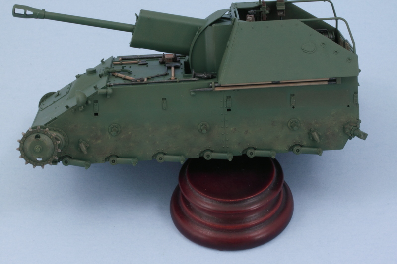
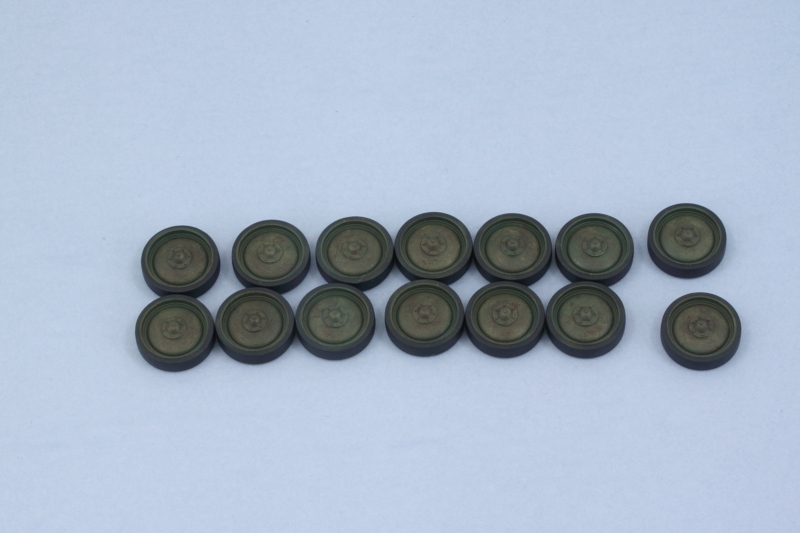
Road wheels also got some wear and attention. 


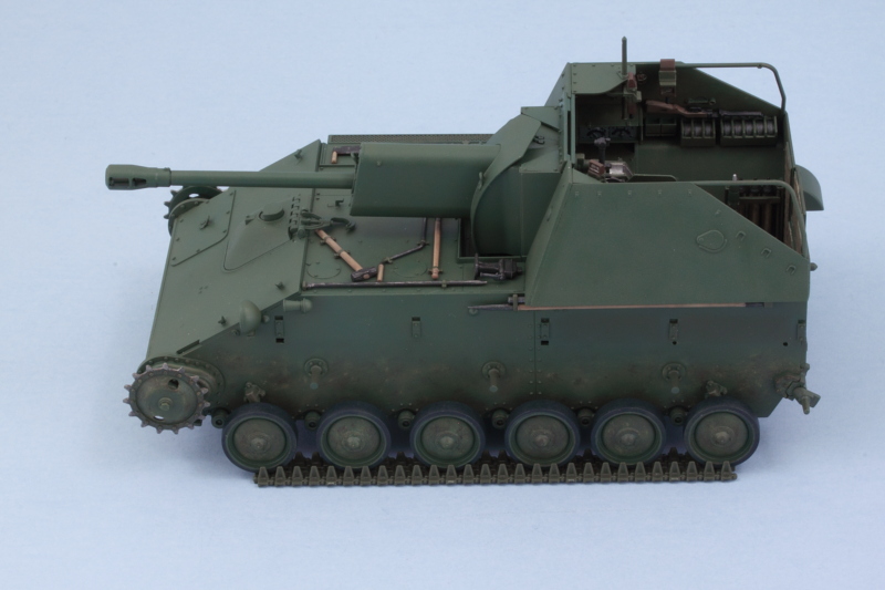
I installed the 6 road wheels per side but left off the idlers for now. I used liquid glue on the arms and cleaned up the long bottom run of the tracks so it could help serve as a guide to ensure all the wheels lined up together while the glue set. 


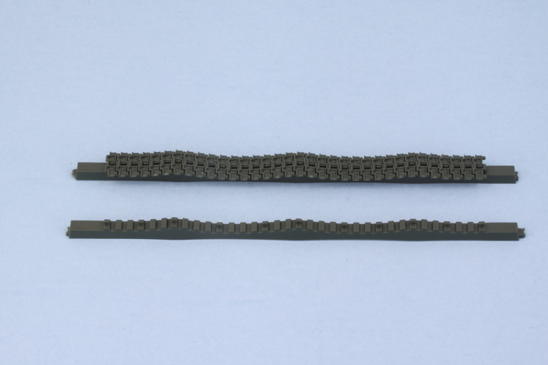
While the road wheels were setting up, I turned my attention to the individual track links. At the start of the instructions they indicate that 6 of the A33 links are 'not for use', so I removed all but 6 links from the sprue and cleaned them up. They have 2 small attachment points that have to be cleaned up but that's not a big deal. I used a small ziplock baggie to hold the links until needed. The links aren't very big and I used the Optivisor during the clean-up as they don't have a large contact surface with each other and I wanted to be sure I kept as much of that intact as possible. 


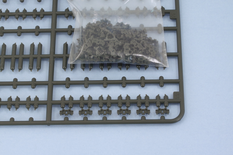
I counted out 34 links as directed in Step 19 and glued them together one at a time into a single straight run using regular glue and tweezers to fit them together. Once the run was together, I used the kit-supplied sag jig to shape the run into the necessary shape. The jig is also plastic, so care is needed in the gluing process so that the run can be safely removed after the glue has set. 


The jigs also have an 'F' mark that is supposed to be the front of the run. I noticed after I took the pic that I had the run ends reversed relative to the F, so I swapped it around before the glue had set. I'm not sure that it really matters all that much but better to be safe than sorry! I also double checked the 'hump' in the sag with three of the return rollers on the left side and everything lined up perfectly there too. 


I'll let the two sagged top runs set up overnight before addressing the curved runs that connect the top and bottom runs together. All told, the instructions call for a combined 63 individual links to create the tracks runs  so that's a total of 126 links between the two sides not including the straight length run already provided.  

  • Member since
    September 2013
  • From: San Antonio, Texas
Posted by Marcus McBean on Saturday, April 2, 2016 5:27 PM

She is really shaping up nicely.  Looking forward to the next set of pictures.

  • Member since
    July 2004
  • From: Texas
Posted by wbill76 on Saturday, April 2, 2016 6:41 PM

Thanks Markus! Appreciate the comments. Beer 

  • Member since
    December 2002
  • From: Bury St Edmunds, Suffolk, England
Posted by Bish on Sunday, April 3, 2016 2:41 AM

Great work Bill, i do like the look of the tools.

I am a Norfolk man and i glory in being so


On the bench: Airfix 1/72nd Harrier GR.3/Fujimi 1/72nd Ju 87D-3

  • Member since
    July 2004
  • From: Texas
Posted by wbill76 on Sunday, April 3, 2016 10:18 AM
Thanks Bish! Beer
  • Member since
    November 2009
  • From: SW Virginia
Posted by Gamera on Sunday, April 3, 2016 11:10 AM

Lookin' sharp Bill, I too love how the tools came out.

"I dream in fire but work in clay." -Arthur Machen


  • Member since
    July 2004
  • From: Texas
Posted by wbill76 on Sunday, April 3, 2016 6:38 PM

Thanks Gamera


The moment of destiny arrived today with the rest of the tracks getting assembled and installed. It also reminded me why I prefer workable tracks vs. statics...but since this is an OOB build, I had to stick with the kit-supplied links. They aren't difficult to work with necessarily, they are just tiny, have to be shaped in a specific way, and then need to hold that shape permanently for painting and detailing. That's a tall order and there was more than one occasion where I had to reattach links together at different moments. 


First up, the remaining connecting runs were assembled as directed in Step 20. 16 links for the front run around the sprocket, 13 links for the rear around the idler. The fact that the sprocket is able to move in the polycap mount was something that I found made life a little harder...the join spots with the upper and lower runs are in places that the weight and position of the links results in the sprocket wanting to turn...not a good thing. I resorted to small narrow strips of tape to hold it all in place while the glue set.


I also made the mistake of trying to 'multi-task' and assembled the runs for both sides at the same time before I realized just how delicate the whole thing is when trying to line up all the different runs.  I was forced into taping and shaping both sides at the same time before the glue set as a result. Now that's a guaranteed exercise in frustration as I quickly discovered, so I'd strongly recommend to anyone else that you work only one side at a time to avoid that. 


After the glue had set, the tape came off, and I had the tracks in 4 pieces per side. I made sure to keep the pieces for each side together from here on out as there's no guarantee that one side would fit the other or vice versa. The return rollers were also finished with their bare metal contact surfaces detailed and all 6 were installed. I found in the fitting process that it's just possible to feed the pre-sagged run over the 3rd roller on the right side but definitely necessary to keep the idler separate since I had added the little mudflap extension under the cooling vent. 


The tracks were hand painted with a base coat of MM Metalizer Non-Buffing Gunmetal then dry brushed with enamel Steel. The last step was an overall wash of MM enamel Raw Umber. Then the tracks were puzzle-pieced together one more time and glued in place. 


Once that's all set, I'll add the fenders to top it all off. 

  • Member since
    May 2015
Posted by Griffin25 on Sunday, April 3, 2016 7:16 PM

Holy cow that's a nice build. The optics and breach details on the gun are awesome. Pro style! 


Griffin

  • Member since
    July 2004
  • From: Texas
Posted by wbill76 on Sunday, April 3, 2016 8:09 PM

Thanks Griffin! Beer Appreciate the comments. 

  • Member since
    July 2004
  • From: Texas
Posted by wbill76 on Sunday, April 3, 2016 10:39 PM

The Hobbyist

Wow, looks like Tamiya is replicating Dragon to a certain extant with the individual track links.  However, Dragon seems to have them pre-cut in their newer kits. 


Sort of. These aren't Magic tracks for sure and is closer to a link-and-length approach. The bottom run for the road wheels was a straight single section piece for example. 

Dragon actually seems to be moving away from Indy links and towards their one piece gluable DS tracks. I personally don't think that's an improvement myself. Beer

  • Member since
    December 2002
  • From: Bury St Edmunds, Suffolk, England
Posted by Bish on Monday, April 4, 2016 12:55 AM

Looking really good Bill.

And your not the only one dissapointed in Dragosn move to DS tracks.

I am a Norfolk man and i glory in being so


On the bench: Airfix 1/72nd Harrier GR.3/Fujimi 1/72nd Ju 87D-3

  • Member since
    October 2015
Posted by Modelrob on Monday, April 4, 2016 6:16 AM

Bill the tracks came out very nicely. I can understand the frustration. I did like the link and length approach Tamyia has been taking.  Again outstanding work on the tracks.


Robert

  • Member since
    November 2009
  • From: SW Virginia
Posted by Gamera on Monday, April 4, 2016 7:46 AM

Whoa, you're almost there now Bill, lookin' good and making great progress. 

Guess I may the only one that likes the DS tracks, then again I mostly build American stuff with tight tracks. I know what you mean about trying to get a decent sag out of the things. 

"I dream in fire but work in clay." -Arthur Machen


  • Member since
    July 2004
  • From: Texas
Posted by wbill76 on Monday, April 4, 2016 12:09 PM

Thanks Bish and Robert


Gamera

Whoa, you're almost there now Bill, lookin' good and making great progress. 

Guess I may the only one that likes the DS tracks, then again I mostly build American stuff with tight tracks. I know what you mean about trying to get a decent sag out of the things.  

Tracks are often a complicated topic when it comes to armor...depending on the subject, the builder's preferences, etc. I agree that for 'live' track system the DS approach is often the better one...but Dragon has started using them for all their kits. Sometimes that works, sometimes not, depending on the kit (and scale!) in question. Over time, I've come to prefer workable tracks even though they add to the cost of a build, take more time, etc. because the tradeoff benefits of flexibility when it comes to weathering and overall build sequence is (generally speaking) worth it. That's just my 2c though! Wink  


JOIN OUR COMMUNITY!

Our community is FREE to join. To participate you must either login or register for an account.

SEARCH FORUMS
FREE NEWSLETTER
By signing up you may also receive reader surveys and occasional special offers. We do not sell, rent or trade our email lists. View our Privacy Policy.