SEARCH FINESCALE.COM

Enter keywords or a search phrase below:

Ships of the American Flag GB 2019 -2021

88081 views
2198 replies
1 rating 2 rating 3 rating 4 rating 5 rating
  • Member since
    July 2014
Posted by modelcrazy on Wednesday, October 7, 2020 3:34 PM

Ben, yes, the lines you have to the box (flag locker) should be lanyards. They are typicaly white or tan but not always. If you look close at the yards you'll see one line attached to the yard and the other end attached to a pully. The ones on the Arizona picture appear to be black. You can also see the white insulators for the wire antennas.

As far as making flags, I'll usually print mine on paper. I use an HP ink (not an advertisement even though I work at HP) because their ink is somewhat water resistent. I will make both sides of the flag or pennant and using white glue I'll attach it to a thin piece of aluminum foil. Then just cut it out fold it over around the lanyard and glue it together. The beauty of doing it yourself is you can vary the size as you wish. Plus you can bend them like they are furled


Steve

Building a kit from your stash is like cutting a head off a Hydra, two more take it's place.


http://www.spamodeler.com/forum/

  • Member since
    June 2018
  • From: Ohio (USA)
Posted by DRUMS01 on Wednesday, October 7, 2020 2:56 PM

Thak you very much GMorrison, Gamera and Modelcrazy, it has been both frustrating and rewarding. I have learned a lot regarding ship building and terminology during this build. 

Modelcrazy.. so are you telling me that those lines going from the box on the flag bridge deck to the antenna array are actually flag lanyards and not antenna lines? if so, perhaps I made them black in error? 

Thanks again GMorrison for your idea of making the open chocks, I learned something new there as well. 

I am gong to have to purchase a USN Flag Set as the kit only has a 48 star flag that is kind of out of register. I want to have the 48 star standard on the bow, the 48 star National Ensign on the stern, and a signal flags to signify "my ship is stopped making no way" (mike).

The only kit decal I am using will be for the "Arizona" name and the numbers above the foul line.

Have any of you used the Eduard pre-painted metal flags? I wonder if they are able to be shaped easily? If not I may try adding the decal to think cooking foil to shape for the wind.

If anyone has a super nice instruction for folding the flags I would greatly appreciate it!

"Everyones the normal until you get to know them" (Unknown)

LAST COMPLETED:

1/35 Churchill Mk IV AVRE with bridge - DONE

NEXT PROJECT:

1/35 CH-54A Tarhe Helicopter


  • Member since
    November 2009
  • From: SW Virginia
Posted by Gamera on Wednesday, October 7, 2020 11:13 AM

That looks simply amazing Ben, love how she's coming.

"I dream in fire but work in clay." -Arthur Machen


  • Member since
    September 2012
Posted by GMorrison on Wednesday, October 7, 2020 10:46 AM

Masterful work Ben.

Yes I'm a full believer that a man has to know his limitations. You took this model pretty far.

Flag halyards are something I usually skip because they can have a way of looking better if I don't.

Low frequency antenna really are a major part of ships of that era.

Your observation about interruptions in the gun deck lifelines is right on. Chocks, bollards, guns, davits, boarding ladders all break the lines.

That is in fact another rigging item, the lifelines. I haven't figured out the best way to differentiate the stanchions and life lines from the bar railings elsewhere.

Bill

 Modeling is an excuse to buy books.


  • Member since
    September 2012
Posted by GMorrison on Wednesday, October 7, 2020 10:12 AM

Masterful work Ben.

Yes I'm a full believer that a man has to know his limitations. You took this model pretty far.

Flag halyards are something I usually skip because they can have a way of looking better if I don't.

Low frequency antenna really are a major part of ships of that era.

Your observation about interruptions in the gun deck lifelines is right on. Chocks, bollards, guns, davits, boarding ladders all break the lines.

That is in fact another rigging item, the lifelines. I haven't figured out the best way to differentiate the stanchions and life lines from the bar railings elsewhere.

Bill

 Modeling is an excuse to buy books.


  • Member since
    July 2014
Posted by modelcrazy on Wednesday, October 7, 2020 9:06 AM

Good work Ben,

Yes, Ships are constantly changing rigging.

Basicly there are three types.

1. Mast stays. These are far more prevelent in the early years of shipping from square riggers to to much less to non existant today. These are cables that hold the mast streight and keep it from moving, hence the name.
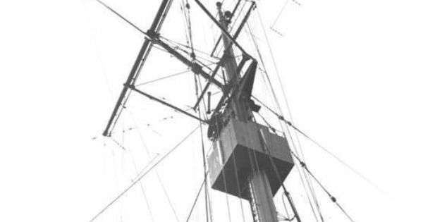
2. Radio antennas. These are typiclly long wire low frequency (LF) antennas. The length of the wire is the same lenth, or a particular fraction of it, to match the length of the frequency transmitted/received to better match the output/input of the transmitter/receiver. These will have a feed, usually somewhere in the center (half or quarter wavelength) to the radio shack.
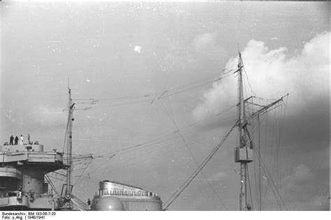
3 The flag lanyards. these are typically rope, sometimes white, that raise/lower and hold the flags as you are aware, including the national insigina while underway. They will typically terminate next the the flag locker. I wasn't a signalman or quartermaster so I have no idea what each flag ment.

Those are the main riggins on a ship. The mid to later war ships will have a white pole, usually on either side somewhare on the ship which is the high frequency (HF) antenna. and of course there are direction finders, short range radios and other such. Messages and other long distance communications were received and transmitted on the LF transmitters since low frequency can travel the curvature of the earth. Their downfall is they are highy susceptible to interferance (AM radio during a thunderstorm for example)

As far as flags. if you are showing her in port, the national ensign flys from the stern pole and the Union Jack (all blue with stars) flys from the bow pole, at least since the late 1770's. Once the lines are cast over and the ship sd detached from the pier, the Union Jack is lowered and the ensign is lowered form the stern and raised on the mast, usually the main mast but not always. This is the USN tradiditon at least, I can't speak for other navys.

Someone correct me if I'm wrong please. Again, I was an ET not a SM or Qm.


Steve

Building a kit from your stash is like cutting a head off a Hydra, two more take it's place.


http://www.spamodeler.com/forum/

  • Member since
    June 2018
  • From: Ohio (USA)
Posted by DRUMS01 on Wednesday, October 7, 2020 12:16 AM

Thanks Steve... that is exactly what I was going for.

Lets talk about rigging, in this case WW2 battleship rigging. The USS Arizona went through several updates from its birth until its demise. Between the major updates from 31 through 41, all of them impacted the rigging in some way. Careful research ensuring the correct images are used is critical to make this model appear as it did sometime between February and June of 1941. 

Image

Image

I am going to only partially rig my model for two major reasons: a) 1/350 I think that is enough said, and b) the level of detail even with the PE is not good or accurate enough to add the full rigging. What I will add will be as close to accurate and complete as I can make it. For example, the rigging going from the signal boxes on the flag bridge platform to the updated antenna array require close inspection. Some modelers add anywhere from 4 to 10 lines on each side. From what I can see on source photos, there appears to be 6 on each side. My problem is trying to figure out how to add those 6 lines on each side when the kit did not have the boxes, and the PE does not have sufficient detail or openings in the signal boxes to add the individual lines. So, how do I add the 6 lines into a 1mm PE box top? Here is how I chose to do it....

First the rigging line I am using on this scale is an item from Europe called Sew-ology. It is 100% nylon, smaller in diameter than a human hair, is very strong, and clear (so it can be colored easily with a permanent marker). The spool is around 2mm in diameter. and contains 400 yards (365 meters). It costs me $2.99 at my nearby large chain Hobby* store. It will last me my life time.....

Image

I figured the best way was to make a rigging jig. The method is very similar to one you would create for making the rat lines for old sailing ships, but simpler. Using stiff matt board (used for photo framing) I measured out the following jig:

Image

The length could've been shorter but it allowed easy movement when worming its way through the antenna array. After weaving the nylon cord through the cuts on the ends of the jig, I had automatically achieved my spacing for the signal boxes. Next was to cut a small, extra thin, guitar E string in the length of the top of the box and then glue it over the hole in the narrow section thus creating the desired spacing for the signal box:

Image

Once cured, I colored the lines with a black permanent marker and removed them from the jig:

Image

This should've been the hard part, but it was not. After 5 attempts I found that the fragile antenna array did not like being stressed to make tight rigging one bit. Then there was another attempt with other rigging that pulled the front of the tower off the tripod mast and almost caused a complete disaster, but I saved it. Six hours later, I am ready to call my simple rigging finished. What is done I believe is accurate, what was omitted could not be done without removing, rebuilding parts, or damaging others (IMHO). 

Here is another sneak peek on the results. If you look close you can see where the signal boxes are and the lines to the antenna array. I hope to have the flags, decals, and water done in the next couple days until then:

Image

Ben

"Everyones the normal until you get to know them" (Unknown)

LAST COMPLETED:

1/35 Churchill Mk IV AVRE with bridge - DONE

NEXT PROJECT:

1/35 CH-54A Tarhe Helicopter


  • Member since
    July 2014
Posted by modelcrazy on Monday, October 5, 2020 5:13 PM

Ben that's just awesome! She looks like she's moured and the water looks like the harbor shallowsYes

I love it!

Steve

Building a kit from your stash is like cutting a head off a Hydra, two more take it's place.


http://www.spamodeler.com/forum/

  • Member since
    June 2018
  • From: Ohio (USA)
Posted by DRUMS01 on Monday, October 5, 2020 4:05 PM

Thanks Steve and Gamera....

I can tell you all that many of these modifications or additions did not come without plenty of trial and error. If it wasn't for me having two of the Eduard PE sets and one set from Toms Modelworks, this ship most likely would never have gotten this far.  

I think I had to make nearly 100 of the open chocks to get enough that looked alike. And if you remember the control towers, I had to make two sets to get one right. I cannot tell you how many times the small parts on the captains barges or aircraft came up missing and I had to use spares or remake them more than once.

Well, I got the rest of the little people painted and added to the ship. All three little birds are also attached. I cannot believe how fragile this thing is! Because of that, I have decided to mount the ship in the display and then begin work on the rigging. 

Once the rigging is done I will finish the water, wear on the hull, and decals and call it done. More photos soon I hope.... here is a little teaser photo of more to come.....

Image

Ben

"Everyones the normal until you get to know them" (Unknown)

LAST COMPLETED:

1/35 Churchill Mk IV AVRE with bridge - DONE

NEXT PROJECT:

1/35 CH-54A Tarhe Helicopter


  • Member since
    November 2009
  • From: SW Virginia
Posted by Gamera on Monday, October 5, 2020 11:19 AM

Oh wow, I think I'd have just left all those parts off. Kudos for putting them in there!!! 

BTW I had to go look up the word 'bollard'... Stick out tongue

"I dream in fire but work in clay." -Arthur Machen


  • Member since
    July 2014
Posted by modelcrazy on Monday, October 5, 2020 7:50 AM

That's one of the things I like about the forums, the ideas. I had that option embedded in my head long ago and it took this post to find it in the attic  dig it out and blow off the dust. Wow, what a difference. 

Steve

Building a kit from your stash is like cutting a head off a Hydra, two more take it's place.


http://www.spamodeler.com/forum/

  • Member since
    June 2018
  • From: Ohio (USA)
Posted by DRUMS01 on Sunday, October 4, 2020 8:05 PM

Thanks Steve, there is just too much going on with this build to just have a final update.

First of all, neither the model kit or the Eduard or Tom's Modelworks PE have any chocks. The ships drawings for the USS Arizona show them in very specific locations (28 total). With the shear amount of them I find it strange that they are not an important part of the model kit or after market detail items (?). Here is a picture of another battleship with the "chocks" identified in the red circles. 


Image

One thing is immediately clear, they are actually integrated in with the hand rails. Unfortunately, the Eduard hand rails, which are already installed, do not have the openings for the chocks. At this point in the build, I am not about to destroy all of the hand railing, and quite possibly the model, just to cut it up for chock openings. After an extensive search throughout the web I am unable to locate 1/350 "open chocks" available to purchase, so I am going to follow GMorrison's suggestion and make them. 

I chose to use SN60 alloy, 0.031" dia. solder. To get the shape I wanted I cut a strip of plastic from a sheet with the specific thickness and width for the chock in 1/350 (eyeball method). Next I coiled the solder around the plastic and cut the solder on one of the flat sides with a hobby knife.

Image

Once the pieces are pulled from the plastic they had to be flattened for the ends to be even with one another. The last step was to use the hobby knifes razor blade to cut the openings consistently on all of them (this was a hit or miss process where only 50% of the chocks were usable), and here is the result.

Image

Next was to identify the locations on the Arizona where the chocks are to be placed. One good thing was once you identified one side, the other was the exact same. Using a precision applicator for the CA cement and tweezers to apply them to the ship, they were applied and painted, here is the results.

Image

Image

My next update will either show final work on the little people, the start of the rigging, or adding the ship to the water. Until next time take care and have fun modeling.

Ben

"Everyones the normal until you get to know them" (Unknown)

LAST COMPLETED:

1/35 Churchill Mk IV AVRE with bridge - DONE

NEXT PROJECT:

1/35 CH-54A Tarhe Helicopter


  • Member since
    July 2014
Posted by modelcrazy on Tuesday, September 29, 2020 7:52 AM

Oh my gosh Ben that's really coming along sir!

Steve

Building a kit from your stash is like cutting a head off a Hydra, two more take it's place.


http://www.spamodeler.com/forum/

  • Member since
    June 2018
  • From: Ohio (USA)
Posted by DRUMS01 on Monday, September 28, 2020 11:52 PM

Thanks Gamera.....

Time for another update... Today I finished adding the remaining hand rails to the decks. When removing the hand rails, start with a new blade in the hobby knife and change it often (P.E. tends to do that to hobby knives). After cutting it from the P.E. fret, I check it again under a good light and remove any remaining nibs. I shaped and attached one segment of the hand rail at a time. This whole process is very time consuming, and that is OK. I chose to take several breaks during the process. When done I still had a couple locations where the ends of two P.E. did not join together tight resulting in a gap. My method of fixing that was to cut and add a very small partial piece from my spares that matched those on the Arizona. I fit it between and carefully align them to look as one piece. 

I'm sure many of you paint your hand rails on the P.E. fret or prior to attaching them, normally I would too. On this build the bare metal P.E. attached to the painted model better so I stuck with that. My next update will show the hand rails painted. During this process I added the rear crane too.

Image

Next was adding the bollards to both decks. The model had bollards molded into the decks, but they were formless blobs of plastic. I purchased replacement (brass) bollards knowing that I would remove the kit ones when removing the other molded in deck details (like stairs). I needed to drill a little hole to fit each bollard on. So after 32 drilled holes and bollards later here it is. I will paint them when painting the hand rails. 

Image

Image

I painted the main antenna array on the fore mast control tower (black). I chose black as that is how it appears in the January 1941 #5 standard gray paint scheme. From July 41 until her demise, they would've been painted haze gray matching the top currents lighter color. Next update I will go over the last P.E.; adding chocks to the decks; adding the fore mast control tower; and final paint prior to rigging.

Till then....

Ben

"Everyones the normal until you get to know them" (Unknown)

LAST COMPLETED:

1/35 Churchill Mk IV AVRE with bridge - DONE

NEXT PROJECT:

1/35 CH-54A Tarhe Helicopter


  • Member since
    November 2009
  • From: SW Virginia
Posted by Gamera on Wednesday, September 23, 2020 9:44 AM

Again, that looks amazing to me Ben. 

"I dream in fire but work in clay." -Arthur Machen


  • Member since
    July 2014
Posted by modelcrazy on Wednesday, September 23, 2020 9:15 AM

Yep, I'd go with the pics. If they show black, go with black. There isn't anyone on this earth that could argue with you except for Lou Conter and Ken Potts, the last of the Arizona survivors. Both are 98 and probably wouldn't remember.

Looks excelent Ben. You have a steadier hand than mine.

Steve

Building a kit from your stash is like cutting a head off a Hydra, two more take it's place.


http://www.spamodeler.com/forum/

  • Member since
    August 2019
  • From: Central Oregon
Posted by HooYah Deep Sea on Tuesday, September 22, 2020 8:50 PM

Well Drums .  .  . If you really want to know .  .  . Beats me !!! Actually, it is one area that I haven't researched (there are so many 'other' areas to fix first). So, go for what you know, it's looking pretty dang good so far. You've done yourself proud. Carry on.

"Why do I do this? Because the money's good, the scenery changes and they let me use explosives, okay?"

  • Member since
    January 2015
Posted by TheMongoose on Tuesday, September 22, 2020 8:32 PM

relocated

In the pattern: Scale Shipyard's 1/48 Balao Class Sub! leaning out the list...NOT! Ha, added to it again - Viper MkVii, 1/32 THUD & F-15J plus a weekend madness build!

  • Member since
    June 2018
  • From: Ohio (USA)
Posted by DRUMS01 on Tuesday, September 22, 2020 8:31 PM

Time to make the main control tower antenna array. The last two updates tell you why I chose to make them. It all starts with a similar diameter steel rod to match the thickness of the PE; in this case I am using a thin guitar "E" string. 

NOTE: If any of you used guitar string before you know that regular plastic sprue cutters will not work, in fact it will damage the sprue cutters softer metal. I cut mine with needle nose pliers, but any cutting plier will do.  

To get the correct lengths I used the ships drawings in the George Stillwell book which are 1/600. If you want to enlarge or reduce the specs or drawings there’s a simple formula; Divide the scale that appears on the drawing by the scale you want, then use the result to reduce or enlarge to scale. For example, if you want to build a 1/350 scale ship but only have a 1/600 scale drawing, divide the scale you have by the scale that you want. So, 350 ÷ 600 = 0.58333. Now round to the nearest whole number, leaving you with 0.58 . So I enlarged the drawings 58% to make them 1/350, measured the antenna sections, and cut accordingly. When all cut, there are 25 pieces at various lengths.

Image

There is no single method when assembling the individual pieces. Some people might assemble them first and then attach them while others may add each piece to the ship. I chose to build the antenna directly on the control tower. The sequence of assembly is a personal choice, but I decided to assemble the antenna under the MG platform first as it has the least risk of being damaged when building the other antennas. Here it is partially done (three legs). 

Image

Next was the rear four leg pyramid antenna as it has the 12' rear range finder platform beneath it to protect it after assembly.

Image

Then I added the shorter side (rear) antennas to both sides, next the longer front antennas. Last was the scratchbuilt 3 piece flag pole above the MG platform and mast beneath it. More WIP photos:

Image

Image

After final tweaking and painting I then added the main mast back to the ship.

Image

Image

These photos show the fore mast control tower sitting on the tripod. I am researching to find the color of the main antenna array, until then they are still brass.

Image

Not sure if you caught it, but I also tossed in a little teaser of the third aircraft on a scratch built dummy car sitting between the #3 and #4 turrets; did you see it?

Still much more to do. To me, it is those little things that bring any model to the next level. I still have plenty of "little things" to do. More updates soon....

Ben

"Everyones the normal until you get to know them" (Unknown)

LAST COMPLETED:

1/35 Churchill Mk IV AVRE with bridge - DONE

NEXT PROJECT:

1/35 CH-54A Tarhe Helicopter


  • Member since
    January 2015
Posted by TheMongoose on Tuesday, September 22, 2020 8:08 PM

Ahh Ben I so enjoy your updates. This thread is going to be the penultimate Arizona resource.

In the pattern: Scale Shipyard's 1/48 Balao Class Sub! leaning out the list...NOT! Ha, added to it again - Viper MkVii, 1/32 THUD & F-15J plus a weekend madness build!

  • Member since
    June 2018
  • From: Ohio (USA)
Posted by DRUMS01 on Tuesday, September 22, 2020 7:24 PM

I agree Steve.... The photo above is  around 1936 from what I can tell. It matches with the drawings in the George Stillwell book. In January 1941 the upper turret and mast area were modified when they added the sky top MG platform. 

I noticed several things when comparing the kit and Eduard PE to the photos. For instance, the front and rear four legged pyramid antennas are not in the kit at all. Instead, when using the kit parts, they have what looks like a large arrow point mounted to the front and rear (?). Looking through the photos, going back to the 1931, I have never seen these arrow/pointers. 

The Eduard PE does provide the forward and aft antennas but they are three legged and not four (?). So I guess I'm fortunate they got bent and destroyed; that way I could make them correctly (smile).

I also noticed that the Eduard side antenna locations are incorrectly referenced as going straight out from the tower. Actually, the rear side antennas are canted to the aft section of the ship by aprozimately 25-30 degrees or so. Even on the 1/250 kit they show the main tower side/rear antennas to be straight out which do not match the drawings.

While I'm bringing things up, I found that most people paint the antenna the ships color (5H, etc.), when they are actually black (perhaps insulation?). If you look at the photos below, the top portion of the front and rear pyramid antennas are the ships color, but all else is black.

Unless HooYah or GMorrison correct me on this, mine are going to be black.

I will post the scratch build of the antennas on the next update.

Ben 

"Everyones the normal until you get to know them" (Unknown)

LAST COMPLETED:

1/35 Churchill Mk IV AVRE with bridge - DONE

NEXT PROJECT:

1/35 CH-54A Tarhe Helicopter


  • Member since
    July 2014
Posted by modelcrazy on Tuesday, September 22, 2020 7:52 AM

Ben, it looks like the one on the lower tower is an ADF antenna. The ones on the superstructure on the mast top appear to be flag lanyard poles. They are tough little buggers to make.

Steve

Building a kit from your stash is like cutting a head off a Hydra, two more take it's place.


http://www.spamodeler.com/forum/

  • Member since
    November 2009
  • From: SW Virginia
Posted by Gamera on Tuesday, September 22, 2020 7:31 AM

Ben: I wouldn't worry too much, she looks amazing to me. If I did that kit she'd probably look like she did after the Japanese bombed her. 

"I dream in fire but work in clay." -Arthur Machen


  • Member since
    June 2018
  • From: Ohio (USA)
Posted by DRUMS01 on Monday, September 21, 2020 11:30 PM

My apologies for no recent updates. My duties have been regulated to finishing all of the fall cleaning outside our home by my Commander Wife and Chief. What little time I got on the Arizona has been both good and not so good. The model does not provide any of the correct details for either masts antenna arrays. I was fortunate that Eduard did provide the updated triangular antenna structure for the fore mast control tower and I was able to fold and added them without much issue.

Image

Image

Image

My problem has been with the antennas on the main mast control tower. Specifically, the very small three legged antenna that are on the sides of the main tower (there are 4). 

Image

So far, I have tried four and destroyed them all. Now consider that these antenna are the width of a human hair and you can see my problem. 

Image

Perhaps I should've added them prior to attaching the main mast to the ship. You see, the mast is vertical and laying the ship on its side might make it easier to attach these little boogers, but that also has many risks for breaking something already attached to the ship. Actually, when looking at the ships photo and that of the antenna, I see where they did not make the all PE antenna accurately anyway (?). Why would you make something in PE to add to the model if it is not completely accurate? I am resorting to making my own antennas for the side of the main tower with the very, very small (thin gauge) guitar "E" string. It is my belief that they will be much stronger and more accurate than the PE after they are assembled. I will post some "work in progress" photos soon.

Here are some of the other main mast antenna already attached as well as evidence of removal of the CA residue (brass showing). Disregard the larger antenna I placed on the lower front of the main tower as they are too large but were used as proof of concept. I think as soon as I have the scratch antenna made and the tower painted, it will be satisfactory.

Image

Till then....

Ben

"Everyones the normal until you get to know them" (Unknown)

LAST COMPLETED:

1/35 Churchill Mk IV AVRE with bridge - DONE

NEXT PROJECT:

1/35 CH-54A Tarhe Helicopter


  • Member since
    November 2009
  • From: SW Virginia
Posted by Gamera on Tuesday, September 15, 2020 7:27 AM

Hehehe, I've never even seen the show even though I was around back then. The most I remember is an old Bob Hope special where in one of the skits he was the captain of a U-boat called the 'Hate Boat' and was stalking the 'Love Boat'. 

"I dream in fire but work in clay." -Arthur Machen


  • Member since
    January 2015
Posted by TheMongoose on Monday, September 14, 2020 7:56 PM

Gamera

Still she looks incredible to me Ben even with more work to do on her. 


Hey Steve would this fit the GB???

Just kidding, I'm not buying it. I thought it was pretty crazy someone actually made a kit of the 'Love Boat' though. Figured everyone could use a smile on an overcast (at least here) Monday. Wonder what scale she is? A diorama with a Japanese destroyer or U-Boat would be pretty cool... Stick out tongue

https://www.ebay.com/itm/124242030686?fbclid=IwAR3mL-dxeZ5ct41wTiK65NzqfSaoaB8BgyNEviX4Y2pIOlOdR0T4fOPEmi0


im disappointed you aren't building this :-(

you really brought back a piece of my youth with this post! I may go look at it!

In the pattern: Scale Shipyard's 1/48 Balao Class Sub! leaning out the list...NOT! Ha, added to it again - Viper MkVii, 1/32 THUD & F-15J plus a weekend madness build!

  • Member since
    July 2014
Posted by modelcrazy on Monday, September 14, 2020 3:01 PM

Ben absolutly fantastic work! I love the little plane garage you made up.

Cliff, well, it's a real ship. I don't know which one she was/is or which line, but that would be a nice addition, assuming someone bought it.

Steve

Building a kit from your stash is like cutting a head off a Hydra, two more take it's place.


http://www.spamodeler.com/forum/

  • Member since
    November 2009
  • From: SW Virginia
Posted by Gamera on Monday, September 14, 2020 11:31 AM

Still she looks incredible to me Ben even with more work to do on her. 


Hey Steve would this fit the GB???

Just kidding, I'm not buying it. I thought it was pretty crazy someone actually made a kit of the 'Love Boat' though. Figured everyone could use a smile on an overcast (at least here) Monday. Wonder what scale she is? A diorama with a Japanese destroyer or U-Boat would be pretty cool... Stick out tongue

https://www.ebay.com/itm/124242030686?fbclid=IwAR3mL-dxeZ5ct41wTiK65NzqfSaoaB8BgyNEviX4Y2pIOlOdR0T4fOPEmi0


"I dream in fire but work in clay." -Arthur Machen


  • Member since
    June 2018
  • From: Ohio (USA)
Posted by DRUMS01 on Monday, September 14, 2020 7:47 AM

Thanks Gamera, still much more to do...

Joe, its nice to see you back in the GB. That looks like it will be a nice kit (with your great skills). Good work so far!

Items accomplished since my last update:

- added the boat cradles and boats on the rear edge of the superstructure deck, beneath the cranes. The model had two unrealistic fat solid ridges to set them on and they were removed prior to adding the wood deck. Eduard provided some very small PE brackets that were only partially correct. The instructions have you bend two small squares on the already small brackets prior to attaching them to the boats and then to the deck. I chose to add the brackets to the deck first to ensure they were parallel to each other and perpendicular to the deck edge. Even with the brackets firmly attached I found that the two small squares on each bracket did not want to cooperate so I too some liberty in making my own nesting planks to lay each boat upon. Here is one of the nesting cradles attached to the deck.

Image

And here is a photo of the boat nested in the cradle.

Image

- I folded the Eduard PE ladders for the main mast and attempted to add them. In my last post I commented that they should be easy to add even though the main mast was already attached to the ship, .... I was wrong. After several attempts and messing up one set of ladders I ended up removing the rear mast assembly from the model. Once I finished cleaning up the CA glue residue I had to repaint the front legs of the mast. When looking at the ladders I noticed that I actually had two other sets; one from my second Eduard PE set, and another from the Tom's Modelworks PE set. I chose to use the Tom's set this time because I noticed that they had a handrail that tied into the platform handrail while the Eduard set did not. Once added I re-attached the main mast back to the deck.

- When looking at the kits Paravanes you could not miss the large raised ejector pin mark on the exposed side of the part. What is a Paravane you ask? The paravane is a form of towed underwater "glider". Initially developed to destroy naval mines, the paravane would be strung out and streamed alongside the towing ship, normally from the bow. The wings of the paravane would tend to force the body away from the towing ship, placing a lateral tension on the towing wire. If the tow cable snagged the cable anchoring a mine then the anchoring cable would be cut, allowing the mine to float to the surface where it could be destroyed by gunfire. If the anchor cable would not part, the mine and the paravane would be brought together and the mine would explode harmlessly against the paravane. The cable could then be retrieved and a replacement paravane fitted. The USS Arizona had four Paravanes attached to the #2 main gun turret. After careful trimming and filing I painted and attached them to the turret. I still may add more detail to them, but they are on the model as well as the hose reels.

Image

How many of you already knew that the USS Arizona had two catapults but actually three aircraft? So the next question would be, where would the third aircraft be stored if there was only two catapults? There is some documentation which shows one catapult storing two of the float planes, but there was another option. The USS Arizona, like many WW2 ships, also had a "dummy car" (cart) on the lower deck that was designed to store one of the aircraft. Feeling like doing something extra special I decided to attempt to create a "dummy car" from scratch to hold my third USU2 Kingfisher aircraft. While there are not many photos of these stowing devices, I have seen a limited amount of pictures of several styles. I chose to make my first attempt using spares from my PE stock. Looking closely at the photos, here is my first attempt (8 pieces shown in brass PE):

Image

I may make another that is lower to the deck with simulated rubber wheels. My goal is to store one of the three aircraft on the deck. More on this as I finalize the "dummy car".

Till next time.....

Ben

"Everyones the normal until you get to know them" (Unknown)

LAST COMPLETED:

1/35 Churchill Mk IV AVRE with bridge - DONE

NEXT PROJECT:

1/35 CH-54A Tarhe Helicopter


  • Member since
    July 2014
Posted by modelcrazy on Sunday, September 13, 2020 8:34 PM

Joe glad to see you back on the Oakland. Yeah, the NC has bee languishing on the ways for a while as well.

Steve

Building a kit from your stash is like cutting a head off a Hydra, two more take it's place.


http://www.spamodeler.com/forum/

JOIN OUR COMMUNITY!

Our community is FREE to join. To participate you must either login or register for an account.

SEARCH FORUMS
FREE NEWSLETTER
By signing up you may also receive reader surveys and occasional special offers. We do not sell, rent or trade our email lists. View our Privacy Policy.