I tried to make the most out of today's efforts since I know I won't be able to do any work on this next weekend due to a business trip to Fiji that requires me to leave on a Saturday in order to arrive on a Tuesday...got to love the International Date Line!
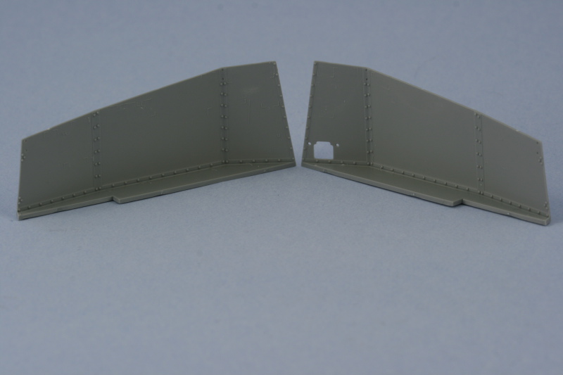
My goal was to get the interior of the fighting compartment completed and I met it but it took a lot longer than I had anticipated. I started in on Step 16 which is a monster of a step with lots of sub diagrams and parts to deal with for the left hand side. The first order of business was to remove several unnecessary molded on locator marks as directed in the instructions. The little box that highlights them in blue misses a couple though, so you have to check carefully to be sure you're getting them all. I did this for both sides and used a micro-chisel on some of the harder to reach ares while the rest were removed with a #11 blade. I should also note that you have to be very careful removing the sides from the sprues as the tops in particular are very thin and it's easy to gouge them if you aren't paying attention.
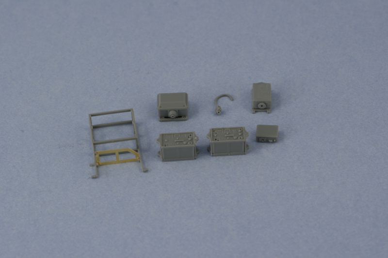
The first item of importance was dealing with all the various and sundry radio gear and power/transformer equipment. Since I intend to wire these up using 0.5mm solder, the appropriate holes were drilled out using a pin vise while the actual wiring will be added later after things are painted and installed. The instructions contain an error in the call-out for the intercom box, it's labelled RA48 when it really is just RA8. I was originally going to use part F85 (it's hidden on the F sprue but there if you look closely) but it tweezerpulted into oblivion, so I had to use the not-for-use part F1 which is designed for the Grille M. The wire has to be re-bent in the opposite direction but otherwise is the same. The radio rack is an exercise in patience to assemble...it's a two-part styrene assembly with a 3rd PE insert to hold the smaller transformer, but each of the styrene parts has 7-8 nodules or sprue attachment points that have to be cleaned up...and since they are very fragile, a new sharp blade will serve you best here. The frames were assembled and the PE insert added alone instead of attached to the transformer as the instructions would have you do it.
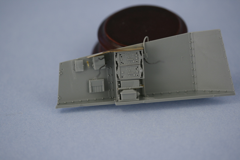
The rack was then installed into position and all of the various gear dry fit to insure it would all play nice together. The smaller transformer that sits on the PE insert had to be sanded down in order to fit into its allotted space. This is a direct result of these parts being reused parts (the RA and RB sprues are generic radio parts) instead of parts specifically designed for the rack they go into. Otherwise everything else fit tight but manageable. I added the solder wiring to the antenna junction box and the intercom box before installing them into the side and left plenty of wire to work with which will be cut down later after painting and the radios are installed. I opted for the PE rain guard for the radios but the instructions are a little vague on how exactly it's supposed to install. The PE part doesn't have a bend line etched into it, so I used pliers and carefully introduced the slight angle that it needs in order to sit properly and flush with the top edge of the side.
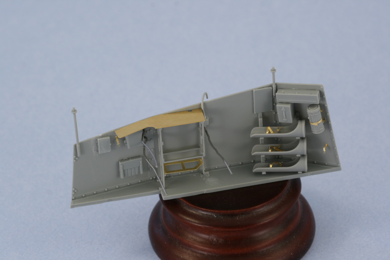
Next I installed all the various boxes and the gas mask container to the front areas as called for with their locator marks. The gas mask PE mount is more complex than it needs to be...it's 3 parts, one for the base, one for the curved holders, and a 3rd for the strap itself. You end up stacking the three parts together and then strapping the container in place and all the detail is hidden as a result...the only benefit from this approach is if you want to show the holder empty. The three shell holders and rack were assembled and I opted to show these empty since it would be extremely tough to paint the rounds once installed and in place. The kit only includes enough parts to show one side or the other empty, but not both, so the right side will have the full racks. Construction of the racks is a tricky exercise, the instructions just show the holders already attached to the racks and then the rack installed into place. I got around this by first gluing F24, the front rack bar, in position without attaching the round holders. The holders were then glued into F25, the rear rack bar, and then glued into place. I used liquid glue to position the "free" ends of the holders into the slots on F24...getting a level and properly angled rack in the process.
I deliberately left of the small seat cushion and the MP40 holder since they would get in the way of adding the radio equipment and completing the wiring, but they were cleaned up and set off to the side for later.
That finished up Step 16, so it was on to 17! This dealt with the right side and the first order of business was to assemble the 12 charge boxes. 10 required the molded on top and bottom ridges to be removed while 2 only required the bottom removed.
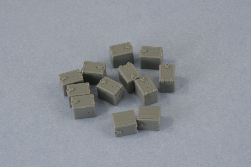
The boxes were then assembled into 2 stacks of 6 each and installed into position. The right stack ends up being taller than it's supposed to be judging by reference photos but by removing 2 rivets on the bracing panel I was able to get it to sit virtually flush with the top of the superstructure side. The left stack sits at the proper height, so not sure what the cause is other than the dimensions on the boxes are incorrect. They don't have to be off by much...just a fraction of a mm each to produce this kind of compound error...but it's there.
The 4 shell racks were added as well...and aside from the instruction diagram, no guidance is provided on their location. I added the first and then the fourth to set the distance and then spaced the second and third as evenly as possible to get them into position. Each shell has a prominent seam that runs top to bottom, so this had to be carefully sanded down with a sanding twig to remove it.
The PE glass block holder was bent to shape and installed in position along with the retaining strap but I decided not to add the block itself as I think it looks better empty. The gas mask container was also added with the MP40 and seat cushion also left off on this side for now.
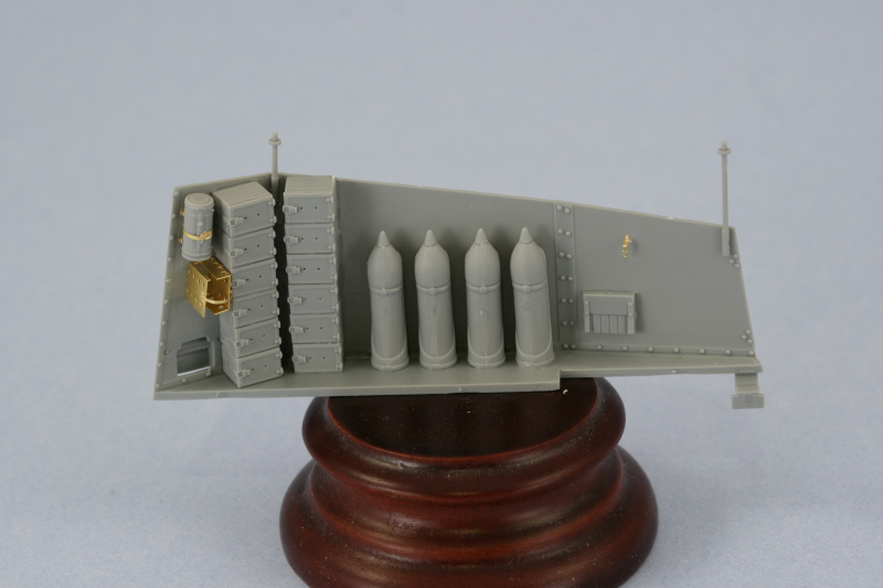
While looking around on the floor for another part I found the missing F85...but since I'd already wired up F1 and glued it into place, I just snipped off the wire portion and swapped it out with the wire portion on F1...that way it had the right height and spacing and wouldn't require any further modification like F85 would've. I also added the rearmost braces, F34, to both sides and test fit them to the hull to be sure they were in the proper position and angle. So, the results of today's efforts...
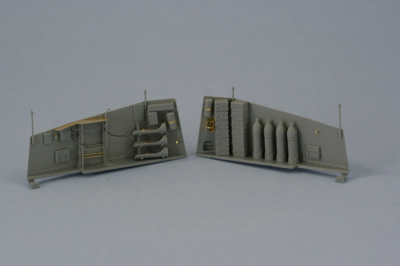
Total Session Time: 7 hours
Total Time to Date: 26.5 hours