Hi Everybody!
My name is Russ, one of the R’s of R&R Modelers, a friendship and collaboration between two modelers to make realistic small scale aircraft model displays. We are not a business, just modelholics who have fun making models. I’ve gotten into making models using AutoCad, and Ron (the other R) is a master of making mini-model displays in 1/350 and 1/144 scales.
Ron and I “met” through this very FineScale Modeler Forum, when he responded to my “A Career in Flight” post featuring a 1/350 scale display of the aircraft my dad flew during his career in the USAF (http://cs.finescale.com/fsm/modeling_subjects/f/2/t/157366.aspx). The planes in the display were designed by me in AutoCad and “printed” by Click2Detail (C2D), who shortly thereafter started a service in which designers can upload their CAD models and they print them, sell them and ship them, and the designer gets a percentage of the sale. I have made several models since then and they are available at:
https://click2detail.com/browse_products.php?total=146&incrementBy=9&id=&pagename_session=browse_products.php&id=&startIndex=27
Ron has acquired several of the models and started working his magic on them. You can see the magic he worked on the 1/144 scale Luscombe 8A Silvaire that I designed on his suggestion at:
http://cs.finescale.com/fsm/modeling_subjects/f/48/t/158982.aspx
And the work of art he is creating for the 1/350 and 1/144 scale Cessna U-3A (310B) at:
http://cs.finescale.com/fsm/modeling_subjects/f/48/t/159017.aspx
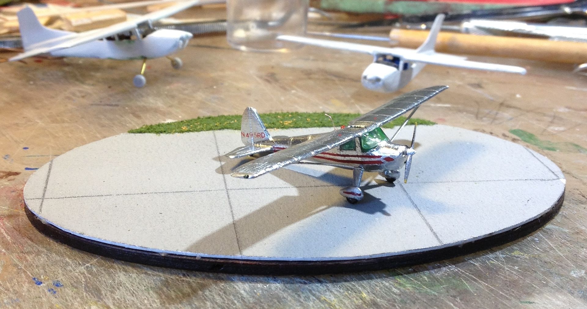
Here’s a peek at what Ron did with the Luscombe.
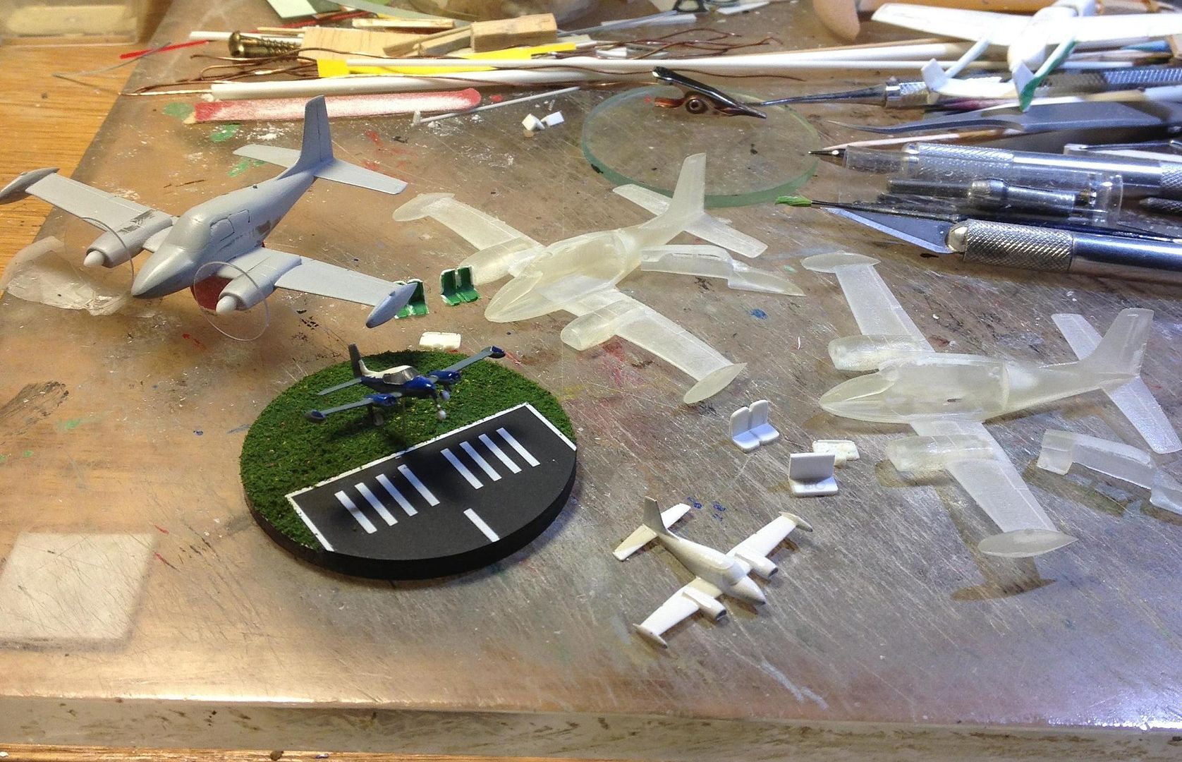
And here’s a peek at what he’s doing with the Cessnas.
Ron is a pilot and flies a Gulfstream IV-SP, so I decided I needed to make one to add to my 1/350 scale fleet. It will be a good addition to the diorama I am planning to do with my models. In this thread I will show the step-by-step process I use to design the models.
So, it all starts with getting plans, which thanks to the internet is fairly easy to do. I don’t need detailed plans, just 3-views, ideally with some cross-sections. Depending on the aircraft however, the sections may not be necessary, provided I can find good pictures of the subject, which is also made easier by the internet. For the GIV, Ron e-mailed me what I needed so I copied the drawings he sent into AutoCAD.

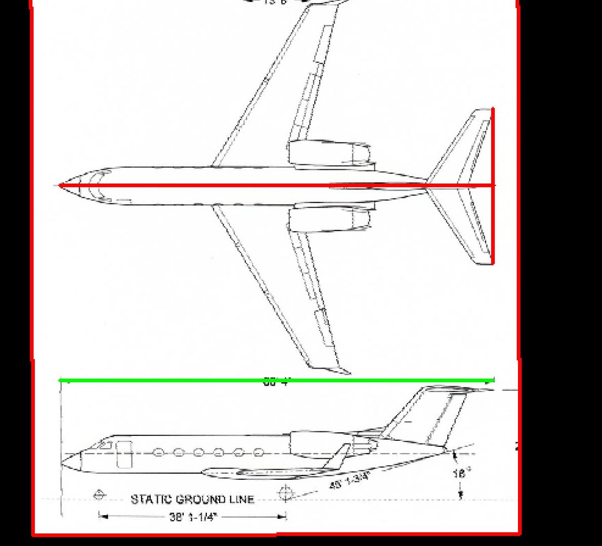
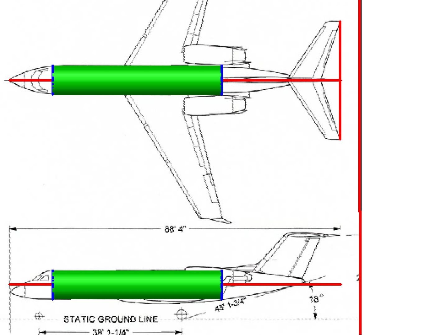
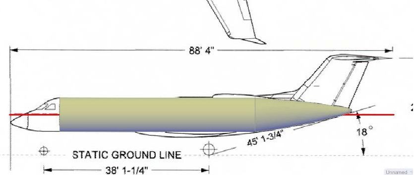
With the plans imported into AutoCAD, the next step was to scale then properly. This isn’t strictly necessary at this point, as I could make the model at any size and scale it later, but I prefer to scale it first so that I know what size things will be as I draw them, without having to convert them. The plans show the length of the plane to be 88’4”, with a wing span of 77’10”. At 1/350 scale, the model will be 3.03” long, with a wingspan of 2.67”. The green line is 3.03” long so I scaled the plans up to match.

I typically start with the fuselage. In this case, I don’t have sections, so I started by drawing a circle matching the outline of the central part of the fuselage.
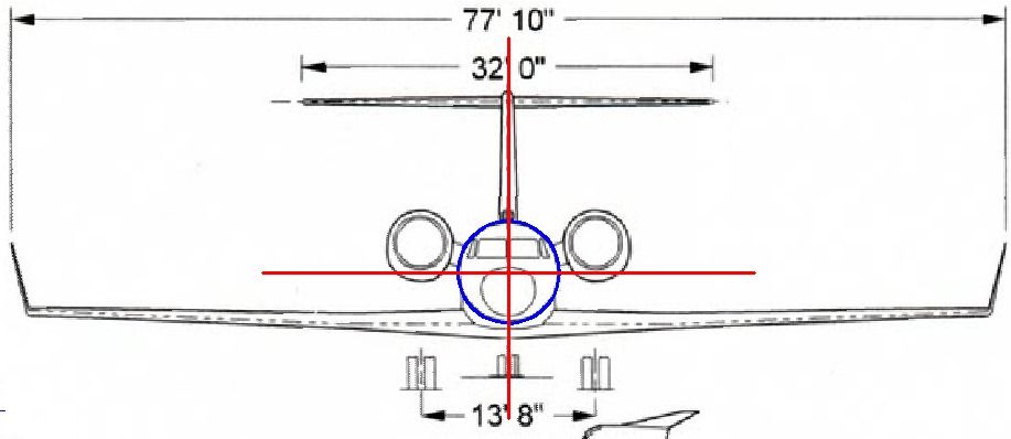
I copied this circle to the top and side views of the aircraft.
At this point, I rotate the circles so that they are perpendicular to the centerline of the fuselage and use the Loft Command to create a solid between the circles.
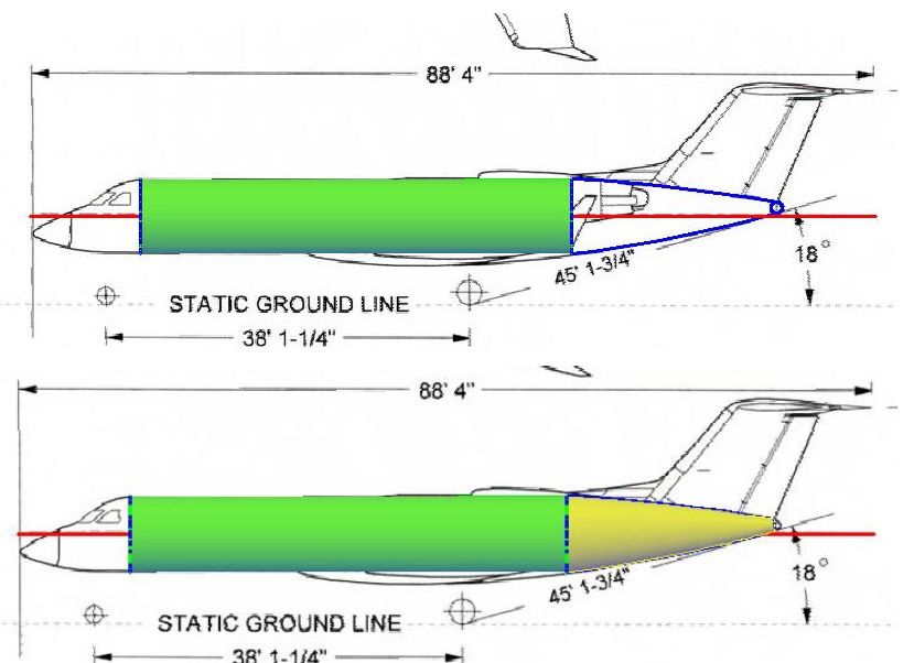
To do the aft end, I started by drawing arcs on the side view, defining the top and bottom of the fuselage to a point just below where the vertical stabilizer attaches where I drew another, much smaller circle. The arc end points are located at the tops and bottoms of the two circles. After rotating the small circle 90 degrees, I again used the Loft Command, but this time I used the arcs as guides for the loft creating a curved surface. The image below shows it before and after lofting.
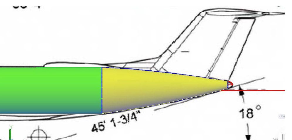
For the very end I created a polyline using an ellipse arc for the top surface, as shown in red in the image below.
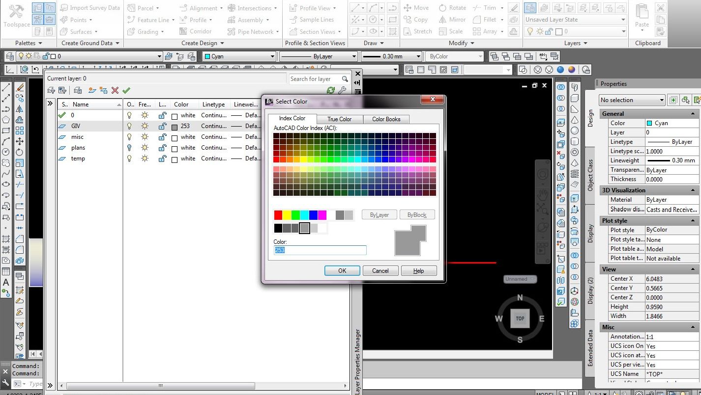
At this point, I should probably point out a couple of features about AutoCAD, the first being that it uses drawing layers that can be turned on and off. You draw on the active layer, which can be changed as desired. The second is that you can change the properties of objects, either individually, or as a layer, and you can easily change what layer an object is on. I typically draw everything on the default “0” layer, with the line thickness set to 0.03mm so that the lines I am working with stand out. I usually work in red for the same reason. When I am finished using construction lines, like the circles and arcs I have drawn, I put them on the Misc layer and turn the layer off. If I delete them they are gone forever. By doing it this way if I later need them, say because I screw something up, I can simply tirn the Misc layer back on and retrieve them.
Now, the images below shows the polyline I previously drew with the model rotated and the Plans layer turned off. The image on the left shows it before Executing the Revolve Command about the central axis of the small circle.

The next thing I did was use the Union Command to join the various solids. I then put it on the GIV layer and changed the color to a shade of gray.
This is a good stopping point for this post. In the next post we will make the front part of the fuselage.
CHEERS!!!