SEARCH FINESCALE.COM

Enter keywords or a search phrase below:

Old Ironsides - Revisiting the classic Revell 1/96 kit

208960 views
510 replies
1 rating 2 rating 3 rating 4 rating 5 rating
  • Member since
    June 2010
  • From: Irvine, CA
Posted by Force9 on Sunday, March 10, 2013 1:12 AM

Marcus

I think the curved hatch coamings are often seen in contemporary models and I rely on more experienced modelers for further justification.

Regarding the "great chase"... I believe James Fenimore Cooper in his "Old Ironsides" book mentions that the main deck stern chasers had to discontinue firing because the angle of the stern gallery was so sharp that the gun muzzles could not extend far enough to be outboard of the windows.  The guns were literally exploding inside the ship directly under the spar deck on each discharge.  Cooper was a personal friend of several of the ship's officers so his account should be reliable.

Cheers

Evan

  • Member since
    May 2012
Posted by Stonemin on Sunday, March 10, 2013 10:56 AM

Question re Revell Kit instructions.

This running thread motivated me to dig out the Constitution kit that's been in my basement and in my plans for too long.  As much as I admire the details discussed, at my age, I'm going to limit myself mostly to OOB with a few improvements.

In assembling the gun deck, the instructions repeatedly say to snap the deck in and DO NOT CEMENT.  my question is WHY?  it seems to me that I have a better chance of minimizing the #$^*@ gap between the pieces if I can firmly fit them agains the hull and each other instead of having them bouncing along.  As it is, it will require some clamping to pull the sides in for a snug fit, but that's manageable.  I could wait until the spar deck is also attached and do it all together, but any guidance is welcome.  I just am hesitant to follow my instincts, not knowing what shoe would drop if I go ahead.  

thanks for the entertaining and enjoyable postings.

STONEMIN

  • Member since
    September 2005
  • From: Groton, CT
Posted by warshipguy on Wednesday, March 13, 2013 10:34 AM

Force9,

It has been a long while since I last checked in. Needless to say that I am still very impressed! In fact, I just sold an old Bluejacket Constitution on EBay and have decided to go with the Revell kit based on the excellence you are showing.

Bill

  • Member since
    June 2010
  • From: Irvine, CA
Posted by Force9 on Wednesday, March 13, 2013 9:51 PM

Hello Stonemin...

I think it makes most sense to go ahead and glue the deck pieces together to eliminate the seams prior to inserting into final position.  It may also make sense to have the gun deck "float" within the hull to prevent unnecessary expansion/contraction issues.  I don't think it would be a big issue, however, to glue it down.  I think that is what I had done on my first build all those decades ago and I don't see any ill effects.  I'm glad you've got your kit out of mothballs and are giving it a go... Even an OOB effort will yield a great result.

Feel free to ask more questions along the way and those of us who've gone before will try to lend sage advice where possible!

Thx

Evan

  • Member since
    June 2010
  • From: Irvine, CA
Posted by Force9 on Wednesday, March 13, 2013 9:54 PM

Bill -

I think the Bluejacket kit is wonderful, but I do hope to demonstrate that the Revell kit can produce a terrific result in its own right... Especially if you incorporate a few of the niceties offered by Bluejacket!  I've been laid low by the wicked virus that has been making the rounds, but I hope to post more progress this weekend.

Please keep checking in!

  • Member since
    June 2010
  • From: Irvine, CA
Posted by Force9 on Saturday, March 23, 2013 1:40 PM

Here is my latest progress on the spar deck:

All of the basic deck modifications complete - includes hatch coamings and shot racks:

I dismembered the Bluejacket PE gratings to suit the Revell hatches:

I've begun to work on the fife rails. The molded belaying pins are mostly bent or broken on these and could use replacements. There is also a lot of flash/seams that need to be cleaned up...

Here is a splurge purchase - scale brass belaying pins (Bluejacket part # 119). I just couldn't resist. I'm sure something suitable could be put in place with small styrene rod with some blobs of glue on top. I think a complete set for this kit would cost about $40 US:

Some test fitted railings and gratings:

Thanks for following along

Evan

  • Member since
    December 2012
Posted by rwiederrich on Saturday, March 23, 2013 2:19 PM

Excellent job.....where did you come about the brass belay pins....I used to find them.....but not any more.

Rob

  • Member since
    March 2009
  • From: brisbane australia
Posted by surfsup on Saturday, March 23, 2013 5:45 PM

Love the work you are doing with her. Just beautiful......Cheers mark

If i was your wife, i'd poison your tea! If Iwas your husband, I would drink it! WINSTON CHURCHILL

  • Member since
    May 2003
  • From: Greenville, NC
Posted by jtilley on Sunday, March 24, 2013 8:58 AM

I'm familiar with two sources for brass belaying pins:  the aforementioned Bluejacket ( www.bluejacketinc.com/.../fittings29.htm ), and Model Expo ( http://www.modelexpo-online.com/search.asp?SKW=cat1_MR%20cat2_S@ ).  [Later edit:  when I click on that link I get a message saying "This category, belaying pins, is empty.]  On the left side of the page, click on "Model ship fittings", then on "rigging Fittings,," then on "Belaying pins."] 

Over the past few months I've had occasion to order the smallest size from each.  I have to say that - slightly to my surprise - I like the Model Expo ones a little better,  Both brands are nicely turned, but a few (not many) in the Bluejacket package are slightly shorter than the others.  (The Model Expo ones, incidentally, look better to my eye than the photos on the website.  Model Expo gets fittings from several manufacturers; I think the ones in the pictures may have come from a different souce than the ones I got.)  Anyway, I can recommend both.

I can't recommend Model Expo's wood belaying pins; they're way out of proportion.  A wood belaying pin on that scale almost has to be, unless the manufacturer uses some super-hard wood, like boxwood.  The only manufacturer I know of that offers boxwood fittings is Calder/Jotika, and all of its stuff is on larger scales.

I strongly recommend replacing the kit-supplied belaying pins in any plastic kit.  Styrene is a wonderful material, but it's too brittle and breakable for stuff like belaying pins.

Youth, talent, hard work, and enthusiasm are no match for old age and treachery.

  • Member since
    June 2010
  • From: Irvine, CA
Posted by Force9 on Thursday, April 18, 2013 9:11 PM

Folks...

Work continues on the spar deck details.

The fore fife rail has been cleaned up a bit along with the topsail sheet bits and connecting pin rails. The kit provided railing includes a nice curve to reflect the camber of the deck so I thought it'd be best to utilize it instead of making a complete replacement.

The main fife rail is unique to Old Ironsides and is nicely executed in the Revell kit. I just cleaned it up and added the brass pins. I think I used a #72 drill bit for the pin holes:

(Those folks building sister ships take note - you'll need to replace the main rail with something more conventional. And for that matter the Trysail mast has to go and the double dolphin striker will need replacement with a single. All are unique to the Constitution).

The kit provided Monkey rail was also utilized after getting cleaned up. This rail is a bit shorter than the others on this deck... Sometimes modelers will think this is odd and replace it with a taller railing. It is intentionally shorter to allow for the "sharks mouth" that wraps around the main mast and supports the end of the mizzen stay:

Thanks for looking

  • Member since
    June 2010
  • From: Irvine, CA
Posted by Force9 on Thursday, April 18, 2013 9:12 PM

The Binnacles were also replaced with scratch built versions. I figured that the effort needed to clean up the kit versions would be similar to what it would take to build new ones. I raised the height slightly - I thought the kit originals were a bit low for the helmsman. I also thought it would help scale down the double wheels - which seem slightly big for this scale. (The smaller binnacles make the wheel seem even bigger)

These will eventually be painted green to match the bulwarks (as shown on the Hull model)

Thx

  • Member since
    June 2010
  • From: Irvine, CA
Posted by Force9 on Saturday, April 20, 2013 7:10 PM

Next up is the double wheel. Early ship records show only two helmsmen assigned to steer, so it has been inferred that she originally only had one wheel. Records from 1804 clearly show four helmsmen to steer so the double wheel has been fitted.

The restored ship in Boston has a beautiful double wheel with elegant stanchions and curved supports.

The Bluejacket version replicates these details nicely, but I think it is a bit under scale. This is an instance where I prefer the Revell version. I did, however, take the trouble to add the curved supports to bring the detail up a notch.

Getting a styrene piece to bend and keep a shape is no fun - especially when this detail will require two bends. The easiest solution is to laminate together two strips and hold them in a mold/pattern until the glue sets. I used .30x.30 Evergreen strip glued to a .10x.30 Evergreen strip. Here was my quick method:


I made the laminated strips long enough to easily bend against the mold and then trimmed them to fit. After a count of 30 or 40 seconds they would hold their shape nicely. I had to make 5 or 6 (okay - maybe 7 or 9) to get four that were worthy. The final product (less painting of course):

Thanks for following along

  • Member since
    June 2010
  • From: Irvine, CA
Posted by Force9 on Wednesday, April 24, 2013 11:22 PM

Here is a bit more progress...

I'm not thrilled with the kit provided galley funnel (later called the "Charlie Noble"). It's not bad, but not good either. It is easily dismissed or overlooked on the foredeck.

The Hull model shows us a short and stocky version:

This is the way to go if I want to be strict with my sources and true to the most historical representation of her August 19, 1812 configuration. But here is where I may exercise some artistic license. If I lay out the boats in the OOB configuration, then this funnel points directly into the butt end of the stored cutter that spans the skids and foredeck. And I've seen several models of ships in this period that display a taller funnel. Even the restored ship today has a much taller Charlie Noble. This, I think, may be an opportunity to utilize something from the AOTS book that adds a bit more interest to this part of the deck. Perhaps not entirely accurate, but what the heck (and maybe I abuse Marquardt too much and should at least acknowledge his version of the ship in this small way).

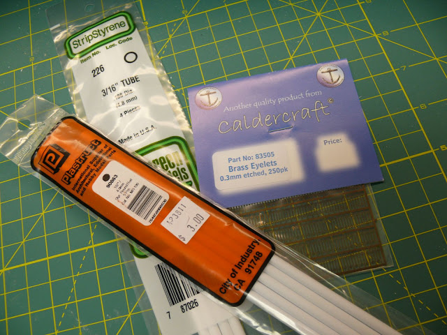
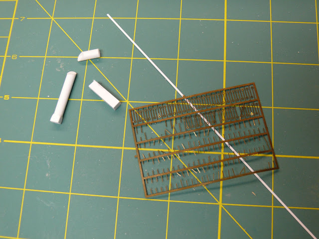
Here are the raw materials; .188 dia. solid rod styrene (Plastruct 90863), .188 dia.tube styrene (Evergreen 196), .188 x .188 styrene (Evergreen 196), some very narrow/thin styrene strip, and the wonderful Jotika .3mm PE brass eyelets.

I glued a hunk of the Evergreen 196 to the base of the solid rod and then shaped the corners with a small file to blend the pieces. Then I cut the 45 degree angle in both the solid rod and the tube and glued them together.

Finally I wrapped the funnel with some narrow styrene and added some eyelet "tie downs" around the perimeter.
The end result:

The baffle plate was easily made - I added a common paper hole punch to my tool box and snipped out a few discs from some thin and wide styrene strips.

Certainly a more interesting element than the alternative. Later I'll add the baffle plate and some small tackle to hold the funnel stable in a heavy breeze.

EG

  • Member since
    June 2011
  • From: New Bern, NC
Posted by Blue Jay on Thursday, April 25, 2013 9:27 AM

Can't believe that after all the research I have done on this site, it took me a year to find your marvelous article (book) on the Constitution.  I have built several in my life, of differing scales, and all OOB.  But this time wanted to build one that was more accurate.  Your article is a wealth of information.  Thank you.

I do have a question concerning the windows on the galleries.  Those on the Revell kit appear to be off scale and look nothing like those shown in the original plans or paintings of that period.  There are usually showing 6 to 9 panes of glass per window.  The Revell kit's window panes seem far to big, thus would be prone to easy breakage.  Or, could the problem be that Revell made the galleries too big, making it necessary to stretch the glass panes?  The galleries on the original plans seem to shorter.  Your thoughts please.

  • Member since
    June 2010
  • From: Irvine, CA
Posted by Force9 on Thursday, April 25, 2013 10:32 PM

Hello Blue Jay...

I'm glad you found my build - hope it inspires you to give the kit another try.

Look back a few pages in this log and you'll find a lively discussion about the stern galleries.  The Revell kit follows the historic Hull model in the Peabody Essex Museum rather than any original plans of the ship.  The stern likely changed many times thru the years so it is hard to pinpoint any window configuration with exactitude.

Now for another deviation:

The Revell kit makes no provision for a ship's bell. This is likely because the historic Hull model does not show a bell - one of many elements that were omitted as the crew scrambled to complete the model in time to present it to Capt Hull before he quit the ship. I would think that a ship's bell would be an integral part of maintaining the shipboard routine in 1812 and needs to be included.

The restored ship in Boston has the bell mounted to the forward face of the mainmast amidships via a small tripod bracket - this is the same solution offered by Larry Arnot in the Bluejacket kit instructions.:

The restored ship had a belfry on the foredeck at one time. It seems like it was removed within the last decade or so and replaced with this version. There may be something official in the historical record to support this, but I can't find any references. Perhaps the c1820 Charles Ware drawing of the United States spar deck is the source:

With the boats positioned in this manner, there is no room for a belfry in the traditional location. Perhaps the mainmast solution made the most sense. (BTW - this would seem to be the reference for the boat layout in the Revell kit).

I don't like the main mast solution. I am thinking of adding a belfry and historical proof be d - m'd! This would also require me to reposition the storage of the boats, but that is easily managed.

Have a look:


Here also is a view down to the gun deck capstan:

Thoughts from other modelers?

  • Member since
    June 2012
Posted by arnie60 on Wednesday, May 1, 2013 1:01 PM

I just bought this a couple weeks ago. Wasn't planning on doing this one quite yet, but It was on sale on Amazon for almost $30 off.  I have been avidly following your exceptional build, checking daily for new installments.

I had originally planned on an OOB build with the exception of planking the decks w/ wood to hide the seams, but now, inspired by your build, I think I just might have to go just a bit beyond that. I went ahead and got the Bluejacket parts list (thanks for the tip on that) and am considering what to replace / augment some of the items in the Revell kit w/ theirs.  Speaking of...have you decided to replace the spar deck guns w/ Bluejackets?(spendy little buggers) Also...did  you get the PE eyelets from them as well?

I am particularly impressed w/ your knowledge and desire to make your build as accurate as possible, but especially that you aren't so fanatical about it that you can't say, "F it" this works for me.

Looking forward to your next installment.

  • Member since
    June 2010
  • From: Irvine, CA
Posted by Force9 on Thursday, May 2, 2013 11:20 PM

Hello Arnie!

Thank you very much for taking such an interest in my build!  I think this kit is great OOB, but can be brought to a much higher level with a little more creativity.  I'd recommend anyone building this beast to at least consider thickening the gun ports and ordering the Bluejacket PE for the hammock cranes.  Replacing the clunky capstan is another good move.

I have not yet decided on my approach for the guns.  The kit provided barrels are very nice and don't beg for replacement, but I do like the more robust look of the BJ versions.  

The PE eyelets are an indispensable addition to any build in this scale - the Heller Victory and 1/96 Cutty Sark can also utilize these.  They are great for the rings on gun port lids among other good uses.  You'll see me add this in many places going forward.

Get 'em from the folks at Jotika in England:

http://www.jotika-ltd.com/Pages/1024768/Fittings/83505.htm

Thanks again for the kind note

EG

  • Member since
    June 2012
Posted by arnie60 on Friday, May 3, 2013 9:23 PM

Thanks for your reply to my reply;

I would like to take advantage of you considerable knowledge here in asking about the hammock cranes. I tried to do some research on them but all I found was info on the use of hammocks on ships to keep crew from being thrown from bunks in high seas, and were often hung on the gun decks. But I could not find anything on the cranes themselves. Any chance you could enlighten me on how they were used. [for all I know here, I may be totally wrong to assume that was what they were used for]

Also... for any and all following this thread. I found a company called "ScaleDecks" that makes laser cut wood decking for ship models. Mostly for 20th century war ships in really, really, small scale (1/700, 1/350 etc.), but I wrote to them and they said they were planning on doing a set for the 1/96 Connie kit at some time. If we all shoot them a shout about it, they might be encouraged to come out w/ it sooner. They sent me a sample and I was quite impressed with the quality. I may just order some uncut sheets to use for this build for now. Here's the link.

http://scaledecks.com/

  • Member since
    June 2012
Posted by arnie60 on Tuesday, May 7, 2013 12:39 PM

Well, forget my question about the hammock cranes. Funny how when you are looking for specific info you can't seem to find it, then run across it while looking for something else. For those of you equally as unschooled as myself, they are used to store the hammocks [huge DOH! from me on this one] and had an added benefit of the stored hammocks acting as a buffer from shrapnel and the like.

I managed to learn this while looking for some images to use later for reference in my build , particularly the rigging for the carronade side tackle, and stumbled across this amazing (to me) site that has a virtual tour of the Constitution. The photos are all high resolution and you can "walk" through the ship all the way down to the hold and up to the main and mizzen mast fighting stations. As you 'navigate' the ship, items are highlighted and a side bar gives you extra photos, drawings, and technical manuals for the highlighted items (which is where I learned about the hammock cranes) as well as historical tidbits.

Here's the link. Just click on the virtual tour on the home page. Took me a while to learn how to get around, but once I figured it out... very cool.

www.history.navy.mil/.../index.html

  • Member since
    June 2010
  • From: Irvine, CA
Posted by Force9 on Saturday, May 11, 2013 11:37 AM

Hello Arnie...

Glad you were able to makes sense of the hammock cranes.  It is an odd term - it seems to imply something related to hanging the hammocks below decks instead of storage above decks along the bulwarks.  It is always said that having the hammocks stored in this way helped protect the crew during battle, but probably not much.  I suppose some protection is better than none.

Having a company finally interested in producing a veneer deck for this kit is a wonderful thing.  I followed the link and like the look of their product.

I'm also glad you discovered the online virtual tour.  You'll see a reference to it in one of my earlier entries.  The photos, drawings, and manuals referenced are also available on a CD that can be purchased in the Constitution museum store or online at the Navy museum store.  The CD seems to have a few extras that might not yet be posted online.  It looks like you are making a serious effort to research the great ship for your own build - bravo!

I am currently struggling with the boat chocks.  Tricky devils they are!  Hope to post something coming out of this weekend.

  • Member since
    June 2010
  • From: Irvine, CA
Posted by Force9 on Sunday, June 2, 2013 11:12 PM

I've dabbled a bit with woodworking over the years and I once had a neighbor who was terrific with wood.  He said that every good woodworker needs to first learn how to recover from his/her mistakes (or learn to hide them) before they can progress to the next level.  I suppose that must also hold true for model ship builders...

I've had to backtrack a bit to correct a big oops.  My original solution for "exposing" the frames of the ship involved glueing strips of .080 x .156" styrene to the inside curvature of the hull.  It seems that over time the inherent tension has caused these to distort the shape of the hull and create a potential headache down the line.  It might be solvable when I install the decks, but I didn't like the idea of all that tension in place over the years.  I decided to do what I should've done to begin with - use thinner .040 x .156" (Evergreen no. 147) built up in two laminated layers.  This is similar to what I had done on my Heller Victory with reasonable success.  There will be much less tension/stress on the shape of the hull when this is done.

After first prying off the original strips (they zinged and zanged all across the workshop as I popped them off individually), I took a few evenings to redo everything:

L1100932.JPG

L1100933.JPG

Much better now.  The remaining distortion will be easily corrected when I install the gun deck.

Whew.

  • Member since
    June 2010
  • From: Irvine, CA
Posted by Force9 on Sunday, June 2, 2013 11:13 PM

On to the quarter galleries... 

I used some very thin strips to approximate the dimensions of the PE brass on the transom windows.  I first cut away the existing gallery window frames and then laid down some horizontal "tracks" of .010 x .030" (Evergreen no. 101) strips along the inner surface.  I then used a slightly thinner .010 x .020" (Evergreen no. 100) strip for the vertical frames - resting them on the even tracks as I glued them in place.  I didn't want too much dimension by using the thicker strips everywhere:

L1100935.JPG

L1100937.JPG

L1100936.JPG

I think this will suffice nicely - gives a more scaled look to the windows while also matching the stern transom window frames.

Thanks again for looking in.

Evan

  • Member since
    August 2011
  • From: France
Posted by phoscar on Wednesday, June 5, 2013 3:36 AM

Bonjour,

Un travail d'artiste, impressionnant, muséographique, historique.

Merci pour cette leçon de modélisme.

  • Member since
    June 2010
  • From: Irvine, CA
Posted by Force9 on Wednesday, June 5, 2013 10:58 PM

phoscar

vous êtes les bienvenus

Cheers

Evan

  • Member since
    August 2011
  • From: France
Posted by phoscar on Thursday, June 6, 2013 2:54 AM

Hello Evan

Thank you for your wonderful job.

marc

  • Member since
    June 2010
  • From: Irvine, CA
Posted by Force9 on Sunday, June 9, 2013 6:49 PM

The Rudder...

The kit provided version was noticeably lacking any copper plating so, just for yucks, I thought I'd build my own version of the rudder...

It has always struck me as odd that the Revell Constitution has a cylindrical rudder head instead of a squared one similar to other period ships. My first thought was to replace that... But then I did some research. It turns out that the good folks at Revell probably got that right! When Constitution was first launched she had a typical "rule joint" type rudder with the square rudder head. This rudder type required a larger opening in the lower transom to allow for the arc of the rudder head as it swung back and forth during turns. Howard Chappelle notes in his American Sailing Navy book that the US Navy had replaced all of their rudders with the newer "plug" type by 1801 or thereabouts. This new innovation utilized the cylindrical shape and moved the rudder head forward so that the center aligned along the same axis as the pintles. This eliminated the arc pattern of the rudder head - instead it spun exactly in line with the pivot point of the pintles. This allowed for a much smaller opening under the transom - and perhaps a tighter feel for the helm. Learn something every day.

Here was my approach:

I glued together four strips of .100 x .156" styrene (Evergreen 177) and did the basic shaping on a small vice using a heavy file. Next I carved a groove into some appropriate rod styrene (same as what I used on the Galley Stove pipe) and affixed that to the top - centered, of course, over the leading edge. Once done, I came back along and notched in the locations for the rudder pintles:

Now I needed to copper plate the thing. I used .010 x .125" (Evergreen 106) for the plates. I whipped up a quick jig (using some available scraps) to help align the "copper" strips while I rolled in the rivet pattern on one edge. I used the smallest roller in my collection to approximate the pattern existing on the kit plating. The rest of the bolt heads I did by hand using my trusty scribe tool.

Took me about an hour to plate each side:

Lastly I came along and added the various straps, spectacle plate, etc.

Here is the result:


BTW - It turns out, the kit provided rudder is actually pretty good. As noted it properly represents the "plug" type version. This is not surprising since it is based on the Campbell plan and he consulted extensively with Chappelle. The rudder edges also taper nicely from forward edge to after edge, and from top to bottom. Ultimately, a very nice upgrade could probably be had by simply adding the copper plates.

Thanks again folks for wading thru my entries!
EG

  • Member since
    December 2012
Posted by rwiederrich on Sunday, June 9, 2013 9:50 PM

Nice work........really nice.

You work in plastic..like I like to work in wood.

Rob

  • Member since
    June 2010
  • From: Irvine, CA
Posted by Force9 on Wednesday, June 12, 2013 10:37 AM

Thank you Rob - I popped in on your build and I'm VERY impressed!  Wonderful stuff!

Folks

Here is another quick exercise I undertook... The Stern Bumpkins.

Many representations of the great ship show the presence of Stern Bumpkins (or Main Brace Spreaders, or Main Brace Bumpkins, etc.). We see an example on the "Loring" model that is currently undergoing restoration at the USS Constitution Museum:

Marquardt includes them in his reconstruction and Olof Eriksen shows them as well in his 1815 version. I went ahead and dabbled a bit with a quick mockup just to get a sense of what might be involved if I go down the same path:


It may be that my version is slightly undersized - hard to tell. I used some spare .080 x .080" strip and some scraps of PE brass. If I do include these I might try .100 x .100" and drill through the bulwark to extend into the hull for more rigidity.

I am hesitant to go this route. I think it is very likely that these were present through most of the War of 1812, but I can't see any evidence that they were fitted during her battle with Guerriere.

The Hull model clearly does not show these and neither do the Michele Felice Cornè, Thomas Birch, or George Ropes Jr. paintings. For now, I think I'll hold off.

EG

  • Member since
    December 2012
Posted by rwiederrich on Wednesday, June 12, 2013 1:26 PM

Indeed...you have something to think about.  During the Connies history she did indeed undergo slight changes to her rigging and her rigging control..not to mention internal issues.

I have encountered similar issues with my Glory of the Seas build.  Unlike the Connie, which is a military ship which typically does not get personal alterations unlike civil ships..which can be altered by their captains at a whim.  The Glory saw many changes during her life.

I would assume so did the Connie to a slighter degree.

I suggest you do what *feels* best to you...since that is what maters anyway.

Rob

  • Member since
    June 2010
  • From: Irvine, CA
Posted by Force9 on Monday, June 17, 2013 8:12 PM

Thanks Rob...

I still have not decided to include the stern bumpkins... Each day I change my mind!

A bit of work on the bow...

It will come as no surprise to folks that I don't like the kit representation of the bow details. The molding for the head timbers and railings is pretty lousy:

There is no consistent guidance across all of the various sources to know exactly how these should look - or even how many head timbers there were in 1812.

Here are some representations:

Modern version:

Corne Paintings:

Hull Model:

In the end I just elected to replace what was on the kit with something a bit more crisp. I wanted, however, to have the head timbers bow outwards in a graceful curve instead of the inward version as molded. I went ahead and laminated together two strips of .060 x .125" styrene (Evergreen 156) using a convenient paint spray can to get the appropriate radius. I taped the strips to the can and came back next day:


I replaced the head timbers one at a time - starting with the most forward (and smallest) one. I left the middle rail intact for support and guidance for the new elements(!):


Some careful filing and test fitting iterations are needed to get everything aligned to the final shape. I'll still have some tuning to do before final glueing. Lastly, I came along with some .030 x .030" strips to add some detail:

I'll likely come along later and give some attention to the weather cloth and upper rails.

Thanks for looking
EG

JOIN OUR COMMUNITY!

Our community is FREE to join. To participate you must either login or register for an account.

SEARCH FORUMS
FREE NEWSLETTER
By signing up you may also receive reader surveys and occasional special offers. We do not sell, rent or trade our email lists. View our Privacy Policy.