SEARCH FINESCALE.COM

Enter keywords or a search phrase below:

Another 1/96 USS Constitution - third time's a charm (I hope)

21617 views
175 replies
1 rating 2 rating 3 rating 4 rating 5 rating
  • Member since
    March 2018
  • From: Chicago suburbs
Posted by Luvspinball on Tuesday, December 20, 2022 9:42 AM

Boat looks great.

As for the dolphin striker, I also rebuilt the whole thing out of wood since the angle on the Revell is wrong.  It is also missing a few tie points as well.  I used hardwood strips for the stikers, as I was very worried about snapping them.  I also beefed them up a bit by adding an additional tapered piece on the back side above the holes for rigging, as well as a small stretcher bar between the strikers about 1/4 of the way down as it is shown in the AOTS book.  When finished and painted, it looks so much better then the plastic one.  BTW mine also had a deep molding depression in the upper portion, which would have stood out, even if I filled it.  Wood is very forgiving.  I probably won't build another plastic sailing ship again.  Maybe just use the hull and fabricate everything else out of wood.

Bob

Bob Frysztak

Luvspinball

Current builds:  Revell 1/96 USS Constitution with extensive scratch building

  • Member since
    March 2019
  • From: San Diego, CA
Posted by Jose Gonzales on Monday, December 19, 2022 5:49 PM

Here is the finished boat:

 20221218_214115 by Jose Gonzales, on Flickr

I had glued the bowsprit cap/double dolphinback striker assembly to the end of the bowsprit, when, guess what? I hit one of the strikers and broke it. It has happened to every model of Constitution I've built, multiple times each. Luckily I had ordered an extra one for my previous builds, but I thought to myself, wouldn't a wooden assembly be less likely to break? Besides, that wishbone-shaped pair of strikers always looked wierd to me.

 20221218_214029 by Jose Gonzales, on Flickr


I cut and filed off the remnants of the broken striker and fashioned a pair from basswood dowels out of the BlueJacket kit, then drilled holes and CA'ed them onto the plastic CAP. Based on how easy it was to drill through the wood I'm worried that basswood will be too soft, so I may look in the LHS for more robust wood dowels.


  • Member since
    September 2012
Posted by GMorrison on Friday, November 11, 2022 2:16 PM

Welcome back, Jose.


I'm very sorry to hear about your parents. That's one of those life milestones.


Bill

 Modeling is an excuse to buy books.


  • Member since
    March 2019
  • From: San Diego, CA
Posted by Jose Gonzales on Friday, November 11, 2022 12:26 PM

Hello all,

Shortly after my last post, I lost both my parents in a span of 6 days. They had both lived long lives, and I am grateful for all they gave me. After a 2 year hiatus, I have resumed  my build. I'm starting small with the ship's boats, using Marquardt as the main source.

 20221011_001556 by Jose Gonzales, on Flickr

  • Member since
    September 2012
Posted by GMorrison on Sunday, May 24, 2020 11:41 AM

Jose, that's hard to answer without more info.

What paint are you using?

What thinner?

What ratio?

What's the weather?


Bill

 Modeling is an excuse to buy books.


  • Member since
    March 2019
  • From: San Diego, CA
Posted by Jose Gonzales on Sunday, May 24, 2020 10:47 AM

 this is a pic of the barque Star of India in drydock for a hull cleaning. I suppose a technically accurate diorama of a ship would at least hint at the type of marine growth seen here.

  • Member since
    March 2019
  • From: San Diego, CA
Posted by Jose Gonzales on Wednesday, May 20, 2020 1:00 PM

This is probably a question for the painting discussion, but I am not an expert on airbrushing. I just started using my new airbrush which I received from my son for Christmas. It's a neo by Iwata, and it's the nicest airbrush I've ever worked with.

I finished priming and painting the ships tops and boats. In both, I found that after a full day of drying, the painted items still seemed tacky to the touch. I was wondering if I overdiluted or underdiluted the paints with paint thinner. Do I just need to let them dry longer?

Thanks,

Jose

  • Member since
    March 2019
  • From: San Diego, CA
Posted by Jose Gonzales on Monday, May 18, 2020 11:08 PM

Hello all,

Time for a quick update. I finished rigging the bobstays (the three lines running from the stem to the underside of the bowsprit) and the bowsprit shrouds (pair of lines running from the bowsprit to either side of the bow near the rear of the trailboards).

 wx_camera_1589682087754 by Jose Gonzales, on Flickr

I served the shrouds along their entire length using the contraption I made. Next on the agenda-the fore-tack boomkins (or bumkins, or even bumpkins, depending on who you ask). Revell provids some very strange slightly s-shaped beams that are rectangular in cross-section. I read somewhere that boomkins did not become rectangular until the 1830's or 1840's, and that the Constitution's boomkins were round spars during the War of 1812, so I determined to fashion my own. I took a small-diameter dowel from the BlueJacket kit, cut two pieces to the same length as the revell pieces, chucked them into my power drill, and used 600 grit sandpaper and needle files to grind down one side of the dowels to a slight taper. I used 0.010x0.040 styrene strip and wrapped it around near the tapered end of the dowels to simulate an iron ring, secured with CA, and drilled 3 holes through the ring to accept 3 eyebolts.

 20200517_164110 by Jose Gonzales, on Flickr

 20200517_164246 by Jose Gonzales, on Flickr

I've painted them black and will mount and rig them shortly.

I've also primed the ships boats, along with the three fighting tops. I'm debating whether or not to mount the swivel guns that come with the BlueJacket kit.

 wx_camera_1589685971812 by Jose Gonzales, on Flickr


Finally, the red tide here in San Diego is waning now, but I got a chance to take a couple of pictures with my less than ideal cellphone camera:

 _DSD7468_edited-1 by Jose Gonzales, on Flickr

 _DSD7465_edited-1 by Jose Gonzales, on Flickr

  • Member since
    March 2019
  • From: San Diego, CA
Posted by Jose Gonzales on Tuesday, April 21, 2020 3:19 AM

Here's a link to the USS Constitution Museum webpage describing recent restoration work on the bobstays: https://ussconstitutionmuseum.org/2017/04/20/springtime-for-uss-constitution/

Cheers!

  • Member since
    March 2019
  • From: San Diego, CA
Posted by Jose Gonzales on Tuesday, April 21, 2020 3:05 AM

I created a serving machine from scrap pieces of wood and a set of gears ordered from an online toy store

 20200418_212832 by Jose Gonzales, on Flickr

 20200419_175156 by Jose Gonzales, on Flickr

I patterned it after the pictures on the Syren website of their serving machine, though mine is quite a bit simpler. The wood joints were reinforced by drilling through the wood joints with a pin vise drill and inserting brass rod.

I have installed 2 of 3 of the bowsprit bobstays.

 20200421_000428 by Jose Gonzales, on Flickr

 20200421_000633 by Jose Gonzales, on Flickr

Interesting differences in the depiction of the bobstays between Revell, BlueJacket, and my other resources. Revell would have you install 6 separate bobstays, 3 per side (3 pairs of separate lines with separate bullseye assemblies for each) while BlueJacket would have you install only 3 bullseyes attached to 3 single lines. The current ship and the previously cited Erik Olafson book say that the bobstays are actually 3 big loops of rope, rope lengths whose ends have been spliced together to form a loop. Th rope passes through holes in the stem/knee at the head of the ship, and have a deadeye siezed at the other end of the loop. The bowsprit has deadeye lashed to it , and the bobstay's deadeye is lashed to the bowsprit deadeye by a lanyard running between them. It is this version that I have chosen to model. I drilled 3 holes through the stem/knee, passed a length of line through each hole, then spliced the ends to form a closed loop. I siezed the deadeyes to the ends of the bobstays and lashed them to deadeyes on the bowsprit with a lanyard. The deadeyes were 3/32' dia from BlueJacket Shipcrafters, and came with the BlueJacket Constitution kit that I'm bashing with the Revell kit. Next up - the bowsprit shrouds. 

  • Member since
    October 2019
  • From: Cape Cod, Mass
Posted by Rick Sr on Thursday, April 9, 2020 8:22 AM

You'll be ok as long as you don't start licking people or barking all night. Smile

  • Member since
    March 2019
  • From: San Diego, CA
Posted by Jose Gonzales on Thursday, April 9, 2020 1:21 AM

Hi all!

Some small updates:

 20200408_073005 by Jose Gonzales, on Flickr

I've mounted the bowsprit, installed the gammoning (my first real rigging on the model), and stropped the spritsail yard. I defaulted to the revell yard instead of trying to make one from the wood dowels that came with the BlueJacket kit. After painting the yard Modelmalster Aircraft Interior Black, I figured it looked plenty good enough. I have, however, carved a jib boom from the dowels becase the revell plastic version looks a little ragged due to the molds being so old. Pics to come.

 20200408_073019 by Jose Gonzales, on Flickr

I've installed ringbolts on the spar deck to retract the slides carrying the carronades. I will not mount the training tackles for all guns, but perhaps I may install one and crew the gun - perhaps firing the morning salute. I've also carved and mounted a couple of larger cleates for the main braces. I am now facing a dilemma - whether or not to install bumpkins on either side of the stern for the main braces. From my previous builds, I know the braces have a tendency to rub against the boats mounted in the stern davits; bumpkins might spread the braces out far enough so that they won't run into the boats. If I recall correctly, Evan (Force9) tried outfitting bumpkins (aka boomkins) - I'll review his build for ideas. The Hull model does not have them, and I believe the Corne paintings of Constitution vs Guerriere don't show theim, but the Ware plans of the USS United States (Constitution's sister ship and one of the original 6 US frigates) do show them:

 45-Ware-15-DeckPlans by Jose Gonzales, on Flickr

 Note - the Ware plans are available from the USS Constitutution Museum website under modeler's references. Revell clearly consulted these plans, especially in regard to the spar deck boat posiions over the main hatch.


  • Member since
    October 2019
  • From: Cape Cod, Mass
Posted by Rick Sr on Tuesday, April 7, 2020 3:41 PM

Strawberry shortcake?_

  • Member since
    September 2012
Posted by GMorrison on Tuesday, April 7, 2020 3:33 PM

I've become my dog. I spend all day sleeping, yearning for car rides, or wandering around the house looking for something to eat...

 Modeling is an excuse to buy books.


  • Member since
    October 2019
  • From: Cape Cod, Mass
Posted by Rick Sr on Tuesday, April 7, 2020 3:33 PM

I can't have mine at the bench. He's nosy and keeps sticking his head in the way. When you tell him to get out of the way, he licks you!

I talk to the ghosts of models gone by.

  • Member since
    October 2019
  • From: Cape Cod, Mass
Posted by Rick Sr on Tuesday, April 7, 2020 3:29 PM

Big Smile  


  • Member since
    May 2006
  • From: Chapin, South Carolina
Posted by Shipwreck on Tuesday, April 7, 2020 9:07 AM

Luvspinball

I 'm talking to the dogs a lot more.


If you are like most people. you will learn a lot if you listen to them!

On the Bench:

Revell 1/96 USS Constitution - rigging

Revell 1/48 B-1B Lancer Prep and research

Trumpeter 1/350 USS Hornet CV-8 Prep and research


  • Member since
    March 2018
  • From: Chicago suburbs
Posted by Luvspinball on Tuesday, April 7, 2020 7:54 AM

I 'm talking to the dogs a lot more.  Not sure why, since they are asleep half the time. 

Bob Frysztak

Luvspinball

Current builds:  Revell 1/96 USS Constitution with extensive scratch building

  • Member since
    October 2019
  • From: Cape Cod, Mass
Posted by Rick Sr on Tuesday, April 7, 2020 6:34 AM

Guns are fastened in to the gun deck. Thanks for that picture, putting in the messenger cables now and that picture has been a great help. BM posted a picture of HMS Victory. Those pictures are a great help. After the messenger cable is finished, it will be time to tie in the guns.

Have you guys had a propensity to talk to yourselves during these builds?

  • Member since
    September 2012
Posted by GMorrison on Saturday, March 14, 2020 6:41 PM

That is a wonderful drawing. It suggests how the messenger was rigged when the anchors were raised, with the eyes and lashing.


 Modeling is an excuse to buy books.


  • Member since
    March 2019
  • From: San Diego, CA
Posted by Jose Gonzales on Saturday, March 14, 2020 6:21 PM

 918xfJIVWcL by Jose Gonzales, on Flickr

This is one of the drawings on which I based my gun deck design and my rigging of the capstan, anchor cables and messenger cables. It describes the HMS Victory's system, but I believe the Constitution's system cannot have been much different. Note the heavy vertical beams just next to the rearmost pumps, designed to keep the messenger cable away from the pumps. I placed similar structures next to my pumps:

 _DSD2146 by Jose Gonzales, on Flickr

  • Member since
    October 2019
  • From: Cape Cod, Mass
Posted by Rick Sr on Saturday, March 7, 2020 7:25 PM

Thanks Jose. The plans I have show the cables dropping through the gun deck through spurling holes just forward of the main hatch. But they also show chain cable instead of hemp for the anchor cables. I think these plans are for the refit done sometime in the late 1830s.

I've started painting the hull on my third Constitution and will be using a lot of what I have seen here on that build.

Your build and Bob's are excellent and very good tutorials, as is Bill"s with his HMS Victory. I hope my third will be just as well.


  • Member since
    March 2019
  • From: San Diego, CA
Posted by Jose Gonzales on Saturday, March 7, 2020 1:33 PM

 _DSD7448 by Jose Gonzales, on Flickr

I finished the head. I added a couple of seats of comfort to each side. Revell's placement of the single seat on each side is illogical, as several rigging lines pass directly over the seat, and there would be no room to sit on it without having to duck them. I had to take into account where the bumpkins or boomkins would pass through the head rails.

  • Member since
    March 2019
  • From: San Diego, CA
Posted by Jose Gonzales on Saturday, March 7, 2020 1:19 PM

Yes I agree with your decision.  If any bulwark cutting were to be done, it probably would have been best done before even assembling the hull. 

Im going to take a good look at how the deadeyes actually line up with the carronade ports. I may end up completely  rebuilding the channels, modifying the deadeye locations.

  • Member since
    October 2019
  • From: Cape Cod, Mass
Posted by Rick Sr on Thursday, March 5, 2020 10:14 AM

Not going to do any fixing as it seems not practible. Would it be easier for you to adjust chains a little to improve carronade interference? The chains molded into the hull aren't very prominent.

  • Member since
    October 2019
  • From: Cape Cod, Mass
Posted by Rick Sr on Tuesday, March 3, 2020 6:44 AM

I am working on my gun deck and think I can cut my spar deck bulwarks level with the gun deck and rebuild them, using the spar bulwarks I would have off my parts kit. Maybe.

Any suggestions on where to place them regarding carronade ports? 

  • Member since
    March 2019
  • From: San Diego, CA
Posted by Jose Gonzales on Tuesday, March 3, 2020 12:42 AM

Hi again,

With regard to the Hull model at the Peabody Essex Museum, here are my 2 cents worth. 

The model was built by a sailor/group of sailors on the ship, who, while intimately familiar with the details of the ship, did not have a draftsman's or nautical engineer's eye for scale or proportion, hence the oversized guns on the spar deck, the distorted proportions in the shape of the hull and perhaps, the spacing of the gun ports, in particular the forward ports.

In his review, Mr Eriksen points out how early portions of the build were more carefully executed than later portions; for example, the gun deck was fully planked, but the spar deck was completed using larger pieces of wood. 

All of this points to the larger truth, that while the model is a historical treasure with a wealth of useful information, including the rigging detail and color scheme, it should not be considered an accurate scale representation.

Cheers,

Jose

  • Member since
    March 2019
  • From: San Diego, CA
Posted by Jose Gonzales on Tuesday, March 3, 2020 12:03 AM

 forecastle guns by Jose Gonzales, on Flickr

Here is a picture of the front third of the Constitution as she appears today. The carronade ports are not directly between the gun deck ports, but are logically spaced to allow the deadeyes and shrouds to run between both gun deck and spar deck ports.


Unfortunately the Revell spar deck ports are very poorly spaced, as are the deadeyes.

 _DSC8071 by Jose Gonzales, on Flickr

Four deadeyes/lanyards between the second and third gun deck ports, and the placement of the spar deck ports for the carronades are nowhere near where they should be to optimally fit between the deadeyes/lanyards. I'm too far along to fix either the deadeyes or the carronade ports.

  • Member since
    March 2018
  • From: Chicago suburbs
Posted by Luvspinball on Monday, March 2, 2020 11:23 PM

GMorrison

Looking at the draft drawing vs. model; the quarter deck and forecastle deck carronade locations seem way off on the model.

I suppose the easier thing a modeler could do to revise stuff would be to rebuild the bulwarks.

Bill


Bill,

While that may be something someone just starting on the model could accomplish, mine is way to far into the build to go that route.  I have multiple sources for my build (7 by my count), and the only thing consistent is the inconsistency of the plans.   At some point, you just have to make your best guess based on the evidence at hand and just be happy with your decision down the road.  Based on all the comments I have received over the last 1 1/2 years, I am and will continue to be proud of my build.  And to be brutally honest, only those of us who have taken the time to do this research will actually know the difference.  Most folks will just look at her and marvel at the finished product, without any mind to the numerous agonies we have endured along the way.  Kind of like raising kids: you do your best and hope that you can be proud of the final product.  Either way, I know I have learned a LOT about ships from others on this forum and from my two clubs.

Bob


Bob Frysztak

Luvspinball

Current builds:  Revell 1/96 USS Constitution with extensive scratch building

  • Member since
    September 2012
Posted by GMorrison on Monday, March 2, 2020 10:28 AM

Looking at the draft drawing vs. model; the quarter deck and forecastle deck carronade locations seem way off on the model.

Assuming that the carronades and bulwark construction would be based on  stanchion locations which in turn are extensions of the frames; and that the closely paired stanchions in the drawings are locations for carronades: the drawing's locations more or less centered between the guns below makes the most sense to me.

Note on the drawing that the entry steps lead uo through a port on the drawing. And again, that centers them between two 32 lb guns. 

No problem moving the chesstree.

I suppose the easier thing a modeler could do to revise stuff would be to rebuild the bulwarks.

Bill

 Modeling is an excuse to buy books.


  • Member since
    May 2006
  • From: Chapin, South Carolina
Posted by Shipwreck on Monday, March 2, 2020 7:12 AM

Jose Gonzales

 My contention is that Revell got the gun deck gunports right, except that they added the bridle ports at the forward end of the gun deck, and then added guns at those locations, this last of which is incorrect.


The "model vs draft" is real interesting. I would suppose that Revell did do a good job of laying out the gun ports according to the draft! But what about according to the Hull model? The layout is different. Anyone care to comment on what he real ship might have looked like?

On the Bench:

Revell 1/96 USS Constitution - rigging

Revell 1/48 B-1B Lancer Prep and research

Trumpeter 1/350 USS Hornet CV-8 Prep and research


  • Member since
    March 2018
  • From: Chicago suburbs
Posted by Luvspinball on Sunday, March 1, 2020 11:01 PM

Jose,

Your drawing depicts exactly what I am saying.  Placement of the deadeyes on the foremast channel, if done as shown in the drawing, would seriously restrict the 3rd and 4th caronnades on the spar deck.  In addition, it would also be difficult to properly affix the links and chain plates without interfering with the gun deck doors (especially the full height doors provided on the Revell model).  While I was able to get what looks like relatively even spacing of the deadeyes, it is somewhat different than that shown in the drawing.

Great read on the Hull model and the masting & rigging of her.  I may have to find a copy of that book.

Bob


Bob Frysztak

Luvspinball

Current builds:  Revell 1/96 USS Constitution with extensive scratch building

  • Member since
    March 2019
  • From: San Diego, CA
Posted by Jose Gonzales on Sunday, March 1, 2020 1:02 PM

Hello all,


I photographed my model in profile, then aligned it with a drawing based on the original drafts by William Doughty, a draftsman working under Josiah Fox, the "Inventor" of the original 6 superfrigates:

 model vs draft by Jose Gonzales, on Flickr

As you can see, the gun deck gunports on the Revell line up very well with the original drafts of the Constitution as launched. Even the steps running up the side of the ship are very similar. My contention is that Revell got the gun deck gunports right, except that they added the bridle ports at the forward end of the gun deck, and then added guns at those locations, this last of which is incorrect.

The chains and the spar deck gun ports are another matter. The chesstree through which the main course tack lines run is placed differently - see the orange line. The chainplate patterns and deadeye locations are slightly different. The gun ports are different because as planned, the constitution did not have solid bulwarks on the spar deck. 

These differences don't bother me much - spar deck bulwarks changed throughout her career and are easily modified. But the gun deck gunports did not move - these were built in as part of the frames, and could not be readily moved.

 My beef with the model's configuration has to do with the foremost gunport on the quarterdeck and the rearmost gunport at the forecastle (foc'sle for short). There is only a sliver of a bulwark forward of that foremost gun port, barely enough to anchor the breach ropes for the carronades mounted, and certainly not enough to rig any tackles. To extend the bulwark, I would have had to move the entry port further forward, and also move the steps forward. I improvised, but I don't particularly care for my solution. I will post pics shortly.

Cheers,

Jose

  • Member since
    March 2019
  • From: San Diego, CA
Posted by Jose Gonzales on Sunday, March 1, 2020 3:57 AM

In a previously posted thread about the Hull model (http://cs.finescale.com/fsm/modeling_subjects/f/7/t/138375.aspx) Force9 (Evan) includes a link to a partial copy of Olaf Eriksen's outstanding reference, "USS Constitution - All Sails Up and Flying". Here is the link for your convenience: http://books.google.de/books?id=XYUWBpxFZN8C&pg=PR5&dq=uss+constitution+all+sails+up+and+flying&hl=de&ei=hi7NTZDUB4_6sgaqy9m6Cw&sa=X&oi=book_result&ct=result&resnum=1&ved=0CCsQ6AEwAA#v=onepage&q=uss%20constitution%20all%20sails%20up%20and%20flying&f=false


Mr Eriksen opens his book with an assessment of the Hull Model, and how he believes it was built. In short, he believes it was started by one crewmember as an individual project, but when the crew learned that their commander was departing due to family matters shortly after their victory over Guerriere, several members of the crew hastily tag-teamed to finish the model. Lots of shotcuts were taken, So while the model itself is a weath of information, Eriksen concludes that there are also flaws due to its hasty construction. If true, then i would have to suggest that among these flaws may explain the status of the gun deck ports.

Even our late Professor Tilley, while admiring the Hull model, noted the missing detail in the model's hull (no ship's wheel, crude guns, no pin rails) while also lauding the rigging job.


i hope you have a chance to view the extract from the Eriksen book.


Cheers,

Jose

  • Member since
    October 2019
  • From: Cape Cod, Mass
Posted by Rick Sr on Saturday, February 29, 2020 11:13 AM

I have three hulls, one I'm working on, one for spares and the third that I will modify to correct Revell errors to the extent possible, such as the oversized hatch.

I am studying the spare hull to see if I can take the spar deck bulwarks down to deck level and rebuild them so the guns are in alignment. If that turns out possible to do I will adapt hull three accordingly.

  • Member since
    May 2006
  • From: Chapin, South Carolina
Posted by Shipwreck on Friday, February 28, 2020 3:21 PM


Jose Gonzales


That foremost port, which still exists on the current vessel, was originally cut into the hull by Cmdr William Bainbridge after he took command of the ship from Isaac Hull.  But he did not cut it as a gunport, but as a bridle port to assist when mooring or docking the ship. It could be used in a pinch as a gunport but it did not have a gun permanently installed during her active service that I know of.  

I chose to model the ship from the Hull era, closing up that port, as you have.  


Well Jose, I tend to agree wit you; in that my current Connie build depicts the for gun ports closed and no guns behind them (post Hull era). I have 15 guns on deck, not the Revell 16!


The problem I have with that configuration is that the Hull model, with it's 15 guns and 15 ports, has guns deployed in the most forward ports. ON THE HULL MODEL THERE ARE GUN PORTS AT THE LOCATION WHERE WE THINK THE BRIDEL PORT WAS CUT A COUPLE MONYHS LATER BY BAINBRIDGE! Think about that; either we are wrong, or the Hull model is wrong.

On the Bench:

Revell 1/96 USS Constitution - rigging

Revell 1/48 B-1B Lancer Prep and research

Trumpeter 1/350 USS Hornet CV-8 Prep and research


  • Member since
    March 2019
  • From: San Diego, CA
Posted by Jose Gonzales on Friday, February 28, 2020 10:33 AM

Hi all, 

That foremost port, which still exists on the current vessel, was originally cut into the hull by Cmdr William Bainbridge after he took command of the ship from Isaac Hull.  But he did not cut it as a gunport, but as a bridle port to assist when mooring or docking the ship. It could be used in a pinch as a gunport but it did not have a gun permanently installed during her active service that I know of.  

I chose to model the ship from the Hull era, closing up that port, as you have. 

I would be cautious in using the Model Shipways model to create a model of the ship as she appeared during her glory years in the War of 1812. The model, while beautiful and accurate, depicts her as she appears today, not her 1812 configuration. Note her raised spar deck bulwarks, her enclosed waist, the simplified 3-window stern, and her rigging. The stem and head timbers (her schnozz) is massive and the trail boards don't have the dragon decor but instead the red white and blue shield. 

I have started work on the head rails. I chose to use the Revell parts. For a while I contemplated removing the depicted tarred canvas screen and replacing it with netting but after looking at examples of models which had netting replaced I decided to stick with the canvas. Pics soon.

Jose

  • Member since
    March 2018
  • From: Chicago suburbs
Posted by Luvspinball on Friday, February 28, 2020 9:39 AM

The real problem with the Revell kit is that the spar and gun deck gunports are in the wrong place.  Check the plans and look at the gunport spacing.  You will find it a challenge to get the deadeyes properly (unless you use Revell's tiny plastic parts).  It is a very prominent mistake in the foremast/foredeck area.  Pretty bad there - guns zig zag between the two decks and there is almost no room for 5mm deadeyes (proper size).  If you are going to modify something on another ship, look into that before you start.

Bob

Bob Frysztak

Luvspinball

Current builds:  Revell 1/96 USS Constitution with extensive scratch building

  • Member since
    October 2019
  • From: Cape Cod, Mass
Posted by Rick Sr on Friday, February 28, 2020 9:29 AM

I have three kits, one for spares, the one I'm working on and a German kit that I will build later,after using this one as a tutorial. On the German kit I will shorten the hatch. I don't see how to eliminate the extra guns. I used Scale Decks overlay on the current build but will try to lay in a real wood deck on the German build...with the proper size hatch!

On my current build I closed the first gun ports to get to 15 guns per side.But the spacing is off compared to Model Shipway drawings.

  • Member since
    May 2006
  • From: Chapin, South Carolina
Posted by Shipwreck on Friday, February 28, 2020 8:44 AM

[quote user="Rick Sr"]

[quote user="Rick Sr"]

The main spar deck hatch on the revell is way out of scale, too long. The Model Shipway plans are 1/96 and they are old. The main problem with Revell is the main hatch on the spar deck and number of 24s on the gun deck.

 It would be not difficult to shorten the main hatch , the question is would it be worth it. Historically, probably yes, aesthetically probably not. 
 
And that depends on how lazy...??>

[/quote

[/quote]

It would be alot easier to shorten the main hatch, than to reduce te gun ports to 15!

On the Bench:

Revell 1/96 USS Constitution - rigging

Revell 1/48 B-1B Lancer Prep and research

Trumpeter 1/350 USS Hornet CV-8 Prep and research


  • Member since
    October 2019
  • From: Cape Cod, Mass
Posted by Rick Sr on Friday, February 28, 2020 7:27 AM

I used the Scale Decks overlay and it's looking pretty good as work progresses. I think I'll leave that over sized hatch alone. ( I have another Constitution to build and will correct this on that one)

All of the gun port covers had to be adjusted with an exacto knife to fit properly into their openings.

I bought HiS gun carriages since they have an extra piece to assist in mounting the guns to the deck. With the Scale Decks overlay, it will be wood to wood, just great for Gorilla Glue.

In running through my n scale train parts box, I came across an old brass engine bell from an American 2-6-0 locomotive...perfect fot the Constitution.

Working on the gun deck, going over Model Shipway plans and they show the messenger pulley as Bob has on his build, needed a magnifying glass to pick up on it.

  • Member since
    October 2019
  • From: Cape Cod, Mass
Posted by Rick Sr on Thursday, February 27, 2020 7:02 PM

You mentioned that before. I added some evergreen strips on the bulwarks(/) below the gun deck, running bow to stern and ran five I beams from port to starboard with a .042 of an inch  rise off of those. I drew the outline on the Ibeams and sanded at low speed with my dremel following the lines. It is barely visible but is there, hidden mostly by the spar desk.

  • Member since
    September 2012
Posted by GMorrison on Thursday, February 27, 2020 2:19 PM

I can't remember if you are using a wood deck overlay. That'll complicate things for shortening the opening, which is really an area of no deck flanked by a pair of catwalks.

I'd guess the boat beams are too few and too small as well, Easy fix.

And last, if you really want to do something that'll upgrade the whole thing, add camber to the deck.

That's easy to do (LOL) if you take some brass square tubing pieces the width of the ship or a little less in 4 or 5 locations and bend it a little to have a scale 3-4" crown in the middle. Being careful to locate it where it won't interfere with things on the gun deck like guns; glue it to the underside of your deck and clamp until it's dry.


 Modeling is an excuse to buy books.


  • Member since
    October 2019
  • From: Cape Cod, Mass
Posted by Rick Sr on Thursday, February 27, 2020 10:55 AM

[quote user="Rick Sr"]

That's a good idea! I don't know if these will be seen or not.

The main spar deck hatch on the revell is way out of scale, too long. The Model Shipway plans are 1/96 and they are old. The main problem with Revell is the main hatch on the spar deck and number of 24s on the gun deck.

 It would be not difficult to shorten the main hatch , the question is would it be worth it. Historically, probably yes, aesthetically probably not. 
 
And that depends on how lazy...??>

[/quote

  • Member since
    October 2019
  • From: Cape Cod, Mass
Posted by Rick Sr on Wednesday, February 26, 2020 3:38 PM

That's a good idea! I don't know if these will be seen or not.

The main spar deck hatch on the revell is way out of scale, too long. The Model Shipway plans are 1/96 and they are old.

  • Member since
    September 2012
Posted by GMorrison on Wednesday, February 26, 2020 1:24 PM

I really cheated on the capstan on my Victory. I measured the height between decks, found three little wooden thread spools that were about the right length and diameter. Stained them brown, and glued them to the decks as I stacked the decks up. Funny thing, can't even see them.

 Modeling is an excuse to buy books.


  • Member since
    October 2019
  • From: Cape Cod, Mass
Posted by Rick Sr on Wednesday, February 26, 2020 9:49 AM

I took a dowel and drilled out a hole in the gun deck of corresponding size , but in a snug fit, added glue (gorilla wood glue) , then set the post into the gun deck by pushing down on the spar deck. Perfect fit. I also put a dollop of glue on top of the column. Then I waited 24 hours for the glue to set, then took the spar deck out to finish the gun tackles. Don't forget to put wax paper on top so you don't glue the spar deck to the column. The dollop of glue conforms to the bottom of the soar deck.

  • Member since
    March 2018
  • From: Chicago suburbs
Posted by Luvspinball on Wednesday, February 26, 2020 9:28 AM

Most common method I have seen is a simple post running from floor to ceiling, but that is pretty hard to do when you add one deck at a time and still need to route the cable.  An alternative would be to mount the pulley to the bow.

GM: I got your joke about the sty/manger.  Just went with it, since I don't have a better name for it!  "Pulley-holder-thingy" doesn't have a very nautical feel to it.

Bob

Bob Frysztak

Luvspinball

Current builds:  Revell 1/96 USS Constitution with extensive scratch building

  • Member since
    September 2012
Posted by GMorrison on Tuesday, February 25, 2020 3:55 PM

Rick Sr

I found a picture of the gun deck with a capstan, as well as the one on the spar deck. I made up a bass wood capstan for the gun deck, and used candy foil wrapper to simlate the brass around the capstan. Wait until you tackle the Victory. One on each of the three gun decks plus the weather deck!

 Force 9, you, Jose and Bill have really been a help. Thanks to you all. I know it must be a pain. None whatsoever.

I am not familiar with that pulley thing Bob came up with, but it looks to serve it's purpose. So my sty comment was a bit of a joke- the area up at the hause holes was called the manger, and there's usually a partition or at least a coaming of some sort to keep the water that comes in from running all the way down the deck. On a lot of ships, it was also a decent place to keep some live animals, as it was constantly sluiced out.

 Modeling is an excuse to buy books.


  • Member since
    March 2018
  • From: Chicago suburbs
Posted by Luvspinball on Tuesday, February 25, 2020 2:02 PM

Rick Sr

Cool beautiful work. I see you have cables through both hauser holes. What is the second cable for? Are the two white structures the water closets?

Constitution carried four or five anchors with her.  I planned to hang four of them, so hence the second set of ropes.

One of the things I have been unable to find so far that is on the Model Shipway plans is something called a "stopper bill" forward of the bowsprit bits.

Made my own stopper bills (black things with the screw on top that the messenger cable goes around) from pictures off the internet.  If you go to google maps and zoom in on the Constitution, you can take a "personal tour" through the ship.  Screen-shotted the images from there. 

What are the black chains running beside the messenger rope and the anchor cables on the other side?

Chains were not used to anchor the ship, but I thought that having them there for other reasons would just look cool in the stopper bills.

Bob

Bob Frysztak

Luvspinball

Current builds:  Revell 1/96 USS Constitution with extensive scratch building

  • Member since
    October 2019
  • From: Cape Cod, Mass
Posted by Rick Sr on Tuesday, February 25, 2020 12:40 PM

Cool beautiful work. I see you have cables through both hauser holes. What is the second cable for? Are the two white structures the water closets?

One of the things I have been unable to find so far that is on the Model Shipway plans is something called a "stopper bill" forward of the bowsprit bits.

What are the black chains running beside the messenger rope and the anchor cables on the other side?

On the spar deck MS shows a total of four cutters, with only one mounted over the main hatch, the rest hanging on the boat davits. I will place the large cutter over the main hatch, with a smaller one inside the large one, as per Revell, with four on the davits.total 5.

I found a picture of the gun deck with a capstan, as well as the one on the spar deck. I made up a bass wood capstan for the gun deck, and used candy foil wrapper to simlate the brass around the capstan.

I had wiring for leds running through a mount pedestal, the forward one, and my precious little grand daughter pulled the wiring out of the hull....grrrrr. Force 9, you, Jose and Bill have really been a help. Thanks to you all. I know it must be a pain.

Revell took a lot of shortcuts, probably to keep costs down and must have figured no one would see the gun deck very well.


  • Member since
    October 2019
  • From: Cape Cod, Mass
Posted by Rick Sr on Tuesday, February 25, 2020 12:10 PM

I'm using Gorilla wood glue, good stuff, but pinning anyway as I don't trust that glue either. It's a great wood glue and seem sto stick well to plastic too...we'll see.

  • Member since
    October 2019
  • From: Cape Cod, Mass
Posted by Rick Sr on Monday, February 24, 2020 7:39 PM

Awesome! Good recovery!

  • Member since
    March 2018
  • From: Chicago suburbs
Posted by Luvspinball on Monday, February 24, 2020 6:01 PM

here is what I did:

connie sty

Bob

Bob Frysztak

Luvspinball

Current builds:  Revell 1/96 USS Constitution with extensive scratch building

  • Member since
    March 2018
  • From: Chicago suburbs
Posted by Luvspinball on Monday, February 24, 2020 1:06 PM

I will post a picture tonight with instructions.

Bob

Bob Frysztak

Luvspinball

Current builds:  Revell 1/96 USS Constitution with extensive scratch building

  • Member since
    September 2012
Posted by GMorrison on Monday, February 24, 2020 12:45 PM

I think Bob's frigate has one.

Yes, oink.

 Modeling is an excuse to buy books.


  • Member since
    October 2019
  • From: Cape Cod, Mass
Posted by Rick Sr on Monday, February 24, 2020 12:42 PM

A sty? As in  hog sty???

  • Member since
    September 2012
Posted by GMorrison on Monday, February 24, 2020 12:19 PM

You can add a sty up forward of the bitts as well.

 Modeling is an excuse to buy books.


  • Member since
    October 2019
  • From: Cape Cod, Mass
Posted by Rick Sr on Monday, February 24, 2020 12:06 PM

That is what I have done too. I considered altering the bulwarks but do not think that is a practical option. I Glued the kits gunports in the closed position and filled with putty, then extended the gun stripe to hide the alteration.

On the Model Shipway plans where the number 1 guns are on the Revell kit, MS shows two water closets for Warrant Officers and Midshipmen. RHIP!


  • Member since
    May 2006
  • From: Chapin, South Carolina
Posted by Shipwreck on Monday, February 24, 2020 10:39 AM

Rick Sr


Revell shows 16 guns per side on the gun deck, Model Shipways shows 15. Where the 1st gun on each side on Revell plans,


The placement of the guns on the gun deck is a major problem with the Revell kit. They are not spread out enough; the result is an extra gun on each side. You can see this at the midship position (between the bulwarks on the main deck); Revell has 4 guns on the gun deck. According to the Hull model, there should only be 3 guns at that position. The Revell lay out is all wrong, and just about impossible to fix! On my Connie, I refused to use 16 guns per side; so I installed 15 guns and closed the front port on each side!

On the Bench:

Revell 1/96 USS Constitution - rigging

Revell 1/48 B-1B Lancer Prep and research

Trumpeter 1/350 USS Hornet CV-8 Prep and research


  • Member since
    March 2019
  • From: San Diego, CA
Posted by Jose Gonzales on Monday, February 24, 2020 1:42 AM

Hi all!

I've installed ladders for the main hatch at the forward end. A couple of adjustments - 1. I used narrower BlueJacket ladders that I ordered to replace the Revell-provided ladders; 2. I ran the ladders from the aft side of the gun-deck hatch rather than on either side of the gun-deck hatch.

 20200223_223833 by Jose Gonzales, on Flickr

 20200223_223845 by Jose Gonzales, on Flickr

 20200223_223941 by Jose Gonzales, on Flickr

I temporarily placed the cutter into the boat cradle to make sure the boat wouldn't interfere with the ladder access, since the ladders are a little closer together because of the anchor cable and messenger cable. 

I also added rope rails and brass stanchions made from 1/32 diameter brass tubing topped with brass eyelets.

Cheers,

Jose

  • Member since
    October 2019
  • From: Cape Cod, Mass
Posted by Rick Sr on Friday, February 21, 2020 12:50 PM

Looking up spurling pipes!

I can not believe how dumb I am regarding things nautical. Looking up names and terms...sculley, galley, scuttle...a scuttle refers to a hold? Good grief!

I have the Model Shipways Constitution plans. They are nothing like Revell plans.

Revell shows 16 guns per side on the gun deck, Model Shipways shows 15. Where the 1st gun on each side on Revell plans, is water closets for warrant officers, etc,on both sides in place of the guns. On the farm our water closets were called "outhouses";they were tough in the winter, you would stick to them! I can only imagine what using them was like for the seaman ordinary on the bowsprit!

We bought our farm in 1947 after WWII. We had no plumbing or electric until 1953. The farm house was 12 rooms and was built 1n 1842. The biggest body of water we had was two creeks that ran through the lower (southern) fields through 40 acres of woods we had bordering our farm and the one next to us. We had a 10 foot skiff for fishing the creeks and to us that was a "big boat!" powered by two oars.. The creeks were 80 feet to 150 yards wide, 8 feet deep at the deepest spot, trout fishing was amazing.

So what you have here is a die- in- the- wool bewildered landlubber trying to build the USS Constitution. Learning the nautical terms is like learning a new language. I am building (or attempting to build) the Constitution because I love American History, my country, and that ship has always been special to me.

Working with wood in no stranger to me. I built the house I am in now with my own hands because we couldn"t afford to purchase one. But about all I know about ships is that they float in water...God willing!

  • Member since
    October 2019
  • From: Cape Cod, Mass
Posted by Rick Sr on Friday, February 21, 2020 7:41 AM

still can not get pix from album into FSM. Can not find reply window in FSC.

Model Expo plans are in album in Fotki.

These are posted in my fotki forum to share with anyone who wants them.

They are  not Model Expo plans, they are Model Shipways plans, my bad.

They are old.

I am not a pc guru. Sorry about that. I'm lucky I can thurn this thing on!

  • Member since
    October 2019
  • From: Cape Cod, Mass
Posted by Rick Sr on Friday, February 21, 2020 2:33 AM

These plans show 15 25 pounders on each side of the gun deck. 

I went to bed, today I will try to post them on fotki. 

They are to big for one pic so there will be a couple of pix for the spar deck and gun deck.

The rigging sheet is massive. 

I think I'll see if Minute Man Printing can do anything with them. There is no copyright date on them. 

 They are from an old Model Expo kit. 

  • Member since
    September 2012
Posted by GMorrison on Thursday, February 20, 2020 8:07 PM

Rick Sr

... dropping down through what looked like mini hausers in the gun deck, through...

Useless piece of knowledge- those are spurling pipes.

 Modeling is an excuse to buy books.


  • Member since
    September 2012
Posted by GMorrison on Thursday, February 20, 2020 8:05 PM

Rick Sr


It shows two stern bulkheads, for the Commodore as well as the captain, shot storage on the spar and gun decks. The last two long guns were in the Commodores quarters.


Probably they weren't when the Commodore was on board. It was also common in the era of Nelson to have a big piece of canvas stretched on the deck with some type of floor pattern painted on it.

 Modeling is an excuse to buy books.


  • Member since
    October 2019
  • From: Cape Cod, Mass
Posted by Rick Sr on Thursday, February 20, 2020 7:39 PM

I got a copy of Constitution plans, must have been for the 1830s or later as the plans show chain anchor cable. There is the gun deck, spar deck, rigging, transom, cannons and hull.

It shows two stern bulkheads, for the Commodore as well as the captain, shot storage on the spar and gun decks. The last two long guns were in the Commodores quarters.

I will put pix on Fotki and see if I can send tham to FSC. I dnot know how clear they will be.

  • Member since
    March 2018
  • From: Chicago suburbs
Posted by Luvspinball on Tuesday, February 18, 2020 11:49 PM

Rick Sr

I got my dremel out and routed out where the pin rails were going, then without a second thought, painted the bulwarks. Now I will have to follow Bill Morrisons suggestion and pin them using wire. The glue isn't holding. I think Revell should have put a warning about glue and paints in there right up front, but it probably would not have done any good!


Rick,

I had also previously painted my bulwarks before trying to add the pinrails.  I knew the glue wouldn't hold AND I had created the bolt pattern by adding a thin layer of styrene which I had pushed a dulled T-pin into, creating a raised bolt pattern on the other side.  So I had to scrape off the paint and the "raised bolts" before gluing.  Never trusting the CA to hold forever, I also pinned them all through the hull with wire.  Documented it all in my thread.  So I feel your pain.  Luckily I have lots of surgical tools at my disposal, so I was able to find an 1/8th inch cuvette which easily did the trick of scraping down to bare plastic. 

Good luck with yours!  Pinning is the way to go.  Doing it also for all the channels as well.

Bob


Bob Frysztak

Luvspinball

Current builds:  Revell 1/96 USS Constitution with extensive scratch building

  • Member since
    October 2019
  • From: Cape Cod, Mass
Posted by Rick Sr on Tuesday, February 18, 2020 6:41 PM

I think the Constitution went from hemp to chain anchor cables in the 1830s. They had the route to the orlop deck just forwardof the hatch, dropping down through what looked like mini hausers in the gun deck, through the berth deck down to storage in the orlop deck.

If you haven't fixed the cable and ladder problem yet, that might be a solution.

I messed up my second Connie. I got my dremel out and routed out where the pin rails were going, then without a second thought, painted the bulwarks. Now I will have to follow Bill Morrisons suggestion and pin them using wire. The glue isn't holding. I think Revell should have put a warning about glue and paints in there right up front, but it probably would not have done any good!

My first Conni is going well, installing guns now. Waiting on anchor rope as the kit doesn't provide enough if you are planning on rigging the cables and messengers.

  • Member since
    March 2019
  • From: San Diego, CA
Posted by Jose Gonzales on Tuesday, February 11, 2020 8:12 AM

Hi all, 

I did add these "stanchions " to the model, see my previous post from 4-1-2018, the last pic in the post. The stanchions are visible through the main hatch on my May 20, 2018 post and March 26, 2019 post, as are the anchor cable and messenger.

As Bill noted, these are removed during battle, and are probably too flimsy to support the stress presented by the anchor cable and messenger during the raising of the anchors. 

Also, the messenger and anchor cable should not be separated by the ladder, since during anchor raising the two are lashed together.

I have decided to use the narrow ladders I ordered and received from BlueJacket. They are made of white metal and I'm having difficulty trimming off the flash. I will post pics shortly.

Jose

  • Member since
    October 2019
  • From: Cape Cod, Mass
Posted by Rick Sr on Tuesday, February 11, 2020 7:37 AM

Yes they are. I seem to recall some at the hatch corners though that may be a "mismemory".

  • Member since
    October 2019
  • From: Cape Cod, Mass
Posted by Rick Sr on Tuesday, February 11, 2020 7:34 AM

compliment is what you were paid...the I is correct for receiving accolades.

  • Member since
    September 2012
Posted by GMorrison on Monday, February 10, 2020 12:49 PM

Those are quite common on 18th- 19th C warships. They are removable, and part of what would be "cleared for action.

As for the ladders in place now, as per museum ships they are sized and placed to get tourists in and out.

 Modeling is an excuse to buy books.


  • Member since
    December 2006
  • From: Jerome, Idaho, U.S.A.
Posted by crackers on Monday, February 10, 2020 12:28 PM

Are these the support pillars you are referring to ? I never know these pillars existed on that ship.

Anthony V. Santos

  • Member since
    March 2019
  • From: San Diego, CA
Posted by Jose Gonzales on Monday, February 10, 2020 7:49 AM

Thanks for the suggestions.  Unfortunately with the spar deck already installed, I am limited regarding the kind of modifications I can make.

I have purchased from Bluejacket some very narrow ladders. I will try playing with these to see if I can work something out.

Jose

  • Member since
    October 2019
  • From: Cape Cod, Mass
Posted by Rick Sr on Saturday, February 8, 2020 2:16 PM

When I visited the Constitution back in the 60s, I seem to remember support pillars at each corner of the hatch beside the ladders. That is if my memeory isn't fading on me. If my memeory is correct, then you could make use of those pillars or columns as spreaders.

  • Member since
    September 2012
Posted by GMorrison on Saturday, February 8, 2020 10:00 AM

No.s 1 and 2- no bueno.

No. 3- sure why not?

No. 4- put the cable over the top of the forward hatch on the gun deck. During raising, it's going to be off the deck by a distance roughly equal to the height of the midpoint of the capstan.


Bill

 Modeling is an excuse to buy books.


  • Member since
    March 2019
  • From: San Diego, CA
Posted by Jose Gonzales on Saturday, February 8, 2020 9:06 AM

I have a problem.

 20200208_062640 by Jose Gonzales, on Flickr


Can you see what's missing from this picture?

Yes the ladders for the main hatch from the gun deck to the spar deck are missing! I completely forgot about them. Normally, per both BlueJacket and Revell instructions, there would be 2 ladders, one on each side, at the forward end of the hatch. Unfortunately, the space normally occupied by those ladders is now occupied by the anchor cables and messenger cable on either side. 

If I had noticed this earlier, I would have tried to accomodate this somehow. I probably would have put the ladders leading up from the berth deck to the gun deck on the forward half of the hatch on the gun deck, then built a platform of some sort over the rear half of the hatch on the gun deck to accomodate the ladders leading up to the spar deck. Or I might have shrunk the hatch to a smaller size to give more space for the ladders. Revell did not plan on having the cables depicted, so they made the forward hatch too wide.

As it is, I have a few options.

1. Put the ladders in, the feet straddling the cables; alternatively, perhaps add a platform over the cables, then install the ladder

2. Push the cables away from the hatch, then put in the ladders. I would have to put some sort of barricade or guide to keep the cable spread - the force on the ladders while the anchors were being raised or lowered would be too much without the spreaders.

3. Place the ladders somewhere else around the main hatch.

Number 1 - not a good idea. The cables would lift under the tension when manipulating the anchors - the ladders would never be placed over the cables. Number 2 - I don't like the idea of adding spreaders when I have never seen any evidence of them. Number 3 seems most feasible, but where should they go?

Any suggestions?

Cheers,

Jose

  • Member since
    March 2019
  • From: San Diego, CA
Posted by Jose Gonzales on Tuesday, January 28, 2020 12:38 AM

I then started making comparison tables, separated by mast:

 20200127_213231 by Jose Gonzales, on Flickr

I am making comparisons. A lot of the lines belay to similar places but there are some glaring differences. I will need to make decisions for each line as to which ones make best sense, make some choices, and generate a final diagram. I will use as my additional sources the Lennarth Peterson's "Rigging Period Ship Models", the much maligned Marquardt AOTS Constitution book, and the fantastic photos of the Hull model that Force 9 (Evan) shared with us.

  • Member since
    March 2019
  • From: San Diego, CA
Posted by Jose Gonzales on Tuesday, January 28, 2020 12:26 AM

Here are my written out diagrams

 20200127_213956 by Jose Gonzales, on Flickr

 20200127_214004 by Jose Gonzales, on Flickr

  • Member since
    March 2019
  • From: San Diego, CA
Posted by Jose Gonzales on Tuesday, January 28, 2020 12:20 AM

Hi all, 

I'm nearly finished with the spar deck fittings, but I need to plan how im going to rig the ship, so I started working on a belaying pin diagram, in case I need to add cleats or pin rails. 

I want to base my rigging on the famous Isaac Hull model in the Peabody Essex Museum in Salem, MA so I'm keeping the steps to the bowsprit, and not running a pin rail across the front of the bow on the spar deck. 

I traced the belaying diagram at the bottom of the Revell rigging plan minus the number assignments and made several photocopies. I then wrote in the names of the lines being belated. I did this for the original revell diagram, and then did an "adapted" version based on the Bluejacket plans. Here are the original belaying diagrams 

 20200127_213125 by Jose Gonzales, on Flickr

 20200127_213155 by Jose Gonzales, on Flickr

 20200127_213205 by Jose Gonzales, on Flickr

  • Member since
    March 2019
  • From: San Diego, CA
Posted by Jose Gonzales on Friday, January 3, 2020 12:41 AM

Hi Bob, 

Thanks for the complement (still can't get which one, compliment or complement, to use straight Smile ). Your solution sounds brilliant, can't wait to see how the wheel turns out. I love your work too - a lot of what we do is slow work - between waiting for paint to dry, waiting for glue to dry, and the modifications, it took me 3 days to complete and mount my wheel. Eagerly awaiting your next update!

Jose


  • Member since
    March 2018
  • From: Chicago suburbs
Posted by Luvspinball on Friday, January 3, 2020 12:31 AM

fabulous work as always, Jose.

I am also struggling with the wheel, as many of my pins are broken.  Tried to get one from ModelMonkey, but again, many of the pins were broken.  I am modifying the one from ModelMonkey by removing the remaining pins and replacint with the top portion of 8mm brass belaying pins.  Slow work - can only do one per day and need to add 20 pins.  About half way home, but will look much better and be much sturdier.

Bob


Bob Frysztak

Luvspinball

Current builds:  Revell 1/96 USS Constitution with extensive scratch building

  • Member since
    March 2019
  • From: San Diego, CA
Posted by Jose Gonzales on Friday, January 3, 2020 12:09 AM

This update is long overdue. Carronades are complete, as are the pinrails.

 _DSD7423 by Jose Gonzales, on Flickr


The BlueJacket kit came with a pair of cathead carvings. I trimmed them to fit the Revell catheads and glued them on. I also added a cleat on each cathead for the stopper cable, and drilled holes through the end for rigging the cathead blocks:

 _DSD7420 by Jose Gonzales, on Flickr

I chose to use the BlueJacket Fore and Main bitts and fiferails, as the ones from the Revell kit were damaged beyond repair. Here are the fore fiferail and bitts:

 _DSD7419 by Jose Gonzales, on Flickr.

The BlueJacket main fiferails seemed too large and out of scale. I chose to exclude the bottom stanchion sections and just glue the bottom rail directly to the deck. I also chose to use the BlueJacket capstain, visible behind the fiferail:

 _DSD7418 by Jose Gonzales, on Flickr

I chose to use the Revell wheel, with the supports modified a la Force9 (Evan) though I did not do nearly as good a job. I've pictured the installed wheel along with the pieces from the BlueJacket wheel assembly for comparison:

 _DSD7417 by Jose Gonzales, on Flickr

 I found the BlueJacket wheel too small relative to the crewmen's size, and perhaps too stocky. Compare these to the real thing:

 kdk_0493-1024x768 by Jose Gonzales, on Flickr

Note that the original has 10 spokes, but both Revell and BlueJacket offer only 8 spokes.


  • Member since
    July 2013
Posted by steve5 on Monday, November 11, 2019 11:22 PM

nice work on the carronades jose . enjoying your build .


  • Member since
    March 2019
  • From: Post Falls, Idaho
Posted by Sigep Ziggy on Monday, November 11, 2019 7:38 PM

Glad to see you back at it! Love your build and will use it when I get around to building my 'Connie'.

your shipmate,

Ziggy


  • Member since
    March 2019
  • From: San Diego, CA
Posted by Jose Gonzales on Monday, November 11, 2019 5:43 PM

 _DSD6763 by Jose Gonzales, on Flickr

 _DSD6762 by Jose Gonzales, on Flickr

Carronades completed, starting on pinrails. I was planning on using the Revell provided pinrails, but when I pulled out the sprue, nearly all belaying pins were bent or broken.

  • Member since
    March 2019
  • From: San Diego, CA
Posted by Jose Gonzales on Saturday, November 9, 2019 8:54 AM

Hi all

Here is a link to a primary source. It is a hi res pic of a watercolor of the uss president by antoine roux, in the digital collection of the new York public library:

https://digitalcollections.nypl.org/items/510d47d9-7b45-a3d9-e040-e00a18064a99

I would paste the pic itself but it is a high res tiff and too large to post.

And another of the same ship by the same artist, from the website of the USS Constitution Museum:

http://2.bp.blogspot.com/-pj9N-CD2WxM/UJEm-RBABfI/AAAAAAAAAGM/xH0jYBY2JPA/s1600/294_1+USS+President.jpg

There are a lot of very interesting things to be minded from these two amazingly detailed paintings. 

1. During normal sailing, gunport covers were removed...they were removable.

2 in stormy weather, gunport covers were in place with the guns run out, through the covers. This means the covers were half covers, top and bottom, with semicircles cut out to accommodate the guns running between them.

3. Look very closely at the quarter galleries, you will see that there appear to be dead lights in place of windows with only a small actual window.

4. In preparation for the storm, all spars were lowered, presumably to lower the center of gravity and stabilize the ship.

I cannot take credit for these observations as I saw discussions about these topics I n other forums,  but I do love these paintings.  Review Roux's work online , you'll find other amazing art. Note that his work was made during the time his subjects were in their prime.

Cheers


  • Member since
    March 2019
  • From: San Diego, CA
Posted by Jose Gonzales on Wednesday, March 27, 2019 9:44 PM

Hi Bob! The breech lines will go in with the carronade barrels. These are the guns from the BlueJacket Shipcrafters Constitution kit that I'm mashing with the Revell kit. The gun deck guns also come from the BlueJacket kit. The guns and carriages are made of Britannia Metal. I painted the carriages with a ModelMaster red. The barrels have been blackened using a Pewter Black solution from Bluejacket.

  • Member since
    March 2018
  • From: Chicago suburbs
Posted by Luvspinball on Wednesday, March 27, 2019 12:20 PM

Looks good, Jose!  Will you add the breach lines once you install the carronades?  Are those the original Revell carriages, or are they custom?  They look like they are made of wood when I zoom in (and not plastic).

Bob


Bob Frysztak

Luvspinball

Current builds:  Revell 1/96 USS Constitution with extensive scratch building

  • Member since
    March 2019
  • From: San Diego, CA
Posted by Jose Gonzales on Tuesday, March 26, 2019 5:48 PM

 _DSD5639 by Jose Gonzales, on Flickr

carronade carriages mounted and rigged

  • Member since
    March 2019
  • From: San Diego, CA
Posted by Jose Gonzales on Tuesday, March 26, 2019 3:30 AM

Hello all,

I've created a new account to continue this build log. It has been 10 months since my last entry, and not much has happened since then, but a few posts from some other build logs of Old Ironsides has stoked my fires, and I am proceeding full sail ahead!

 _DSD5647 by Jose Gonzales, on Flickr


  • Member since
    December 2005
  • From: San Diego
Posted by jgonzales on Sunday, May 20, 2018 11:30 AM

Hi all,

Work on the model has been slow; life as usual gets in the way. I completed my work on the gun  deck and prepared for laying down the spar deck. A few things got in the way.

1.  I decided to remove the eye bolts from the Bluejacket kit thati had originally mounted on the spar deck bulwarks and replace them with photoetch eyebolts from Dafi that i had purchased for the Heller Victory, so I purchased extra photoetch eyebolts and hooks.  Unfortunately I broke a few of the bluejacket eyebolts while removing them, leaving the straight stems stuck in the bulwarks, I ended up removing them by drilling from the outside to push them out. I installed Dafi's eyebolts and they look pretty good.

2. I had intended on buying planking from BlueJacket to plank over the plastic spar deck, and lower the plastic deck by sanding down the nubs on the  bottom of the plastic. However, instead of buying the intended 9/32 x 1/32 planking, I accidently purchased the 9/32 x 0.020 inch thick planking. This planking was intended to be used as the external planking for the solid wood hull, and was much thinner than 1/32. I had to adjust my plans, and tried to shave down the nubs accordingly. 

Here are pics of the nearly finished spar deck planking.

 DSD_2442 by Jose Gonzales, on Flickr

 DSD_2453 by Jose Gonzales, on Flickr

 DSD_2451 by Jose Gonzales, on Flickr

 DSD_2446 by Jose Gonzales, on Flickr

 DSD_2441 by Jose Gonzales, on Flickr

Jose Gonzales San Diego, CA
  • Member since
    July 2013
Posted by steve5 on Sunday, April 1, 2018 10:53 PM

really enjoying your build jose , 

steve5


  • Member since
    December 2005
  • From: San Diego
Posted by jgonzales on Sunday, April 1, 2018 10:33 PM

Hi all,

I've been working on the model off and on for the last month, time permitting. The post by Crackers showing the two fine models of the HMS Pandora, as well as the McNarry Constitution builds have spurred me on, and I have decided to add as many crewmen as possible. I am also turning around the idea of turning this into  a water diorama with the ship under sail. Since I will be depicting the ship under normal sail, and not at battle stations, I have decided to complete the captain's cabin, including the captain's quarters as well as the great cabin.

To that end, i created furniture from scratch, and built up the temporary dividers. It took a few tries to get the scale correct, hence the two tables and the initial attempt at a chair - see the tiny one, what looks like a child's stool with brass rod legs, as well as the oversized table. The final versions are the ones painted brown.

 DSD_2244 by Jose Gonzales, on Flickr

 DSD_2248 by Jose Gonzales, on Flickr

 2018-04-01_08-31-40 by Jose Gonzales, on Flickr

See the desk in the captain's private quarters

 2018-04-01_08-33-35 by Jose Gonzales, on Flickr

and the sleeping cot covered with a veil.

I assembled the lower masts and bowsprit, and sanded down the seams. I also tried to fix the warpage of the spar deck pieces by gluing wood dowels to the undersides, but u fortunately, the tactic ended up stiffening the decks in a too-straight state, countering against the sheer of the deck (the upward curve of the deck at the bow and stern). I ended up cutting notches into these dowels at regular intervals to try to restore some flexibility to the deck. 

I also started adding some crew to the gun deck. I also had a handful of leftover barrels I obtained for my last build, and installed elm pumps that came from the BlueJacket kit.

 2018-04-01_08-34-23 by Jose Gonzales, on Flickr.

More pics to come shortly.

Jose

Jose Gonzales San Diego, CA
  • Member since
    December 2010
  • From: Salem, Oregon
Posted by 1943Mike on Saturday, February 10, 2018 7:00 PM

This is turning into a magnificent build!

And, yeh, your wife's a keeper. Big Smile

Mike

"Le temps est un grand maître, mais malheureusement, il tue tous ses élèves."

Hector Berlioz

  • Member since
    July 2013
Posted by steve5 on Saturday, February 10, 2018 3:06 PM

man ! that's some library ,


  • Member since
    December 2005
  • From: San Diego
Posted by jgonzales on Saturday, February 10, 2018 2:58 PM

Hi Bill,

Thanks! I appreciate your compliment.

Today is relatively quiet, so I'd like toA  step back and review some things.

First, a list of references I have been using for my last build and this current build:

A Most Fortunate Ship

by Tyrone Martin, Commander USN (Ret)


Old Ironsides, the Rise, Decline, and Resurrection of the USS Constitution

Thomas Gillmer with illustrations by William Gilkerson


Rigging Period Ship Models

Lennarth Petersson


USS Constitution Old Ironsides

Photography by Steve Dunwell


Anatomy of the Ship - The 44 Gun Frigate USS Constitution

Karl Heinz Marquardt


The Anatomy of Nelson's Ships

C Nepean Longridge


HMS Victory - Her construction, career, and restoration

Alan McGowan


The following two books were very inspirational to me and sparked my initial interest in sailing ships:

The Seafarers: The Frigates

Henry Gruppe and Time-Life editors
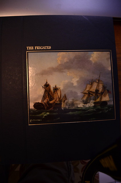
 _DSD2164 by Jose Gonzales, on Flickr

I mentioned to my wife a short while ago that I used to go to the library on weekends and pore over the Seafarers series of books for hours. Look what she got me for my birthday last month! All 22 volumes!

 _DSD2166 by Jose Gonzales, on Flickr

The second book:
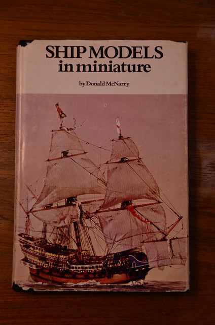
 _DSD2158 by Jose Gonzales, on Flickr

I got a copy of this book from e-bay recently. Donald McNarry was the premier ship modeler of the 20th century,  particularly for small-scale modeling. He built 6 models of the Constitution, all of them portray her early years (Hercules figurehead) and one is a full-sail diorama. They were all built at 1/192 scale
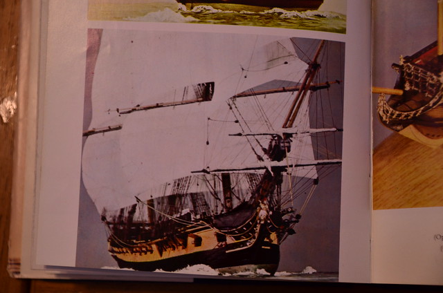
 _DSD2159 by Jose Gonzales, on Flickr

 _DSD2161 by Jose Gonzales, on Flickr
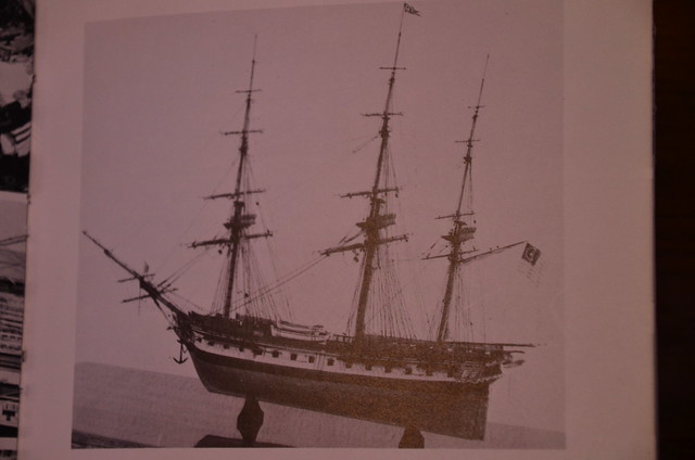
 _DSD2162 by Jose Gonzales, on Flickr

 _DSD2163 by Jose Gonzales, on Flickr

I'm finishing up the gun deck with last few details. I kept the fore and mainsail sheets and tack lines rigged on the gun deck, unlike Force9 (Evan), who got rid of the chesstrees and moved the rigging of these lines up to the spar deck. So now, I have to run the Sheet and Tack lines through the chesstrees and holes in the hull, and belay them to some large cleats that I installed inside the gun deck. As mentioned before by you, Bill, the sheets will be quite long, as the ends of the sails travelled a long way from one tack to the other tack, so I'm looking for references regarding how these long lines (braces, sheets) were belayed and coiled. I haven't seen any references to coil baskets on the Constitution, so if anyone has any references or knows anything about this, I'd be happy to take your suggestions.


Cheers!

Jose


Jose Gonzales San Diego, CA
  • Member since
    September 2012
Posted by GMorrison on Friday, February 9, 2018 11:27 AM

Super work!

The galley stove is nicely done, looks hot, black and shiny.

Can't wait to see more!


Bill

 Modeling is an excuse to buy books.


  • Member since
    December 2005
  • From: San Diego
Posted by jgonzales on Friday, February 9, 2018 11:10 AM

 _DSD2140 by Jose Gonzales, on Flickr

 _DSD2141 by Jose Gonzales, on Flickr

 _DSD2146 by Jose Gonzales, on Flickr

 _DSD2155 by Jose Gonzales, on Flickr

The anchor cables are installed, along with the messenger cable. I've also added shot racks between the guns. 

FYI a messenger cable is a cable of a smaller diameter than the anchor cable, that wraps around the capstan (the anchor cable itself is too thick for the capstan), then loops forward along one side, around a couple of rollers in front, then back to the capstan as a single loop. To haul the anchor, the anchor cable is temporarily nipped to the messenger via a series of small ropes tied around both the anchor cable and messenger. As the capstan is turned, the messenger pulls in the anchor cable. As the cable reaches its dropping point at the main hatch, the nips are undone, and brought back forward to be recirculated. The messenger loop is closed by lashing together eyes at the ends of the messenger cable (last picture).

Jose Gonzales San Diego, CA
  • Member since
    December 2005
  • From: San Diego
Posted by jgonzales on Sunday, February 4, 2018 1:29 PM

Hi all!

Thanks Crackers for posting that pic of Constitution at launch. I seriously considered depicting her from her early days, and even looked up sites that sold figurines of ancient warriors that I might modify to form the Hercules figurehead, but decided to stick to her 1812 configuration. Hercules will have to wait for the next build.

Rob, thanks for asking about the weathering. The hull came pre-painted with copper, and it was already slightly tinged green. My original plan was to copy Force9 and pick out individual copper plates to highlight with bright copper or dark to black. My masking did not work so well and I got a lot of bleed through, and so I determined to go a different route. I saw the pics of old Ironsides going into drydock for her most recent restoration, and noted the look of her copper sheathing as the water was being drained, and choose to copy that look. I bought ModelMaster acrylic Patina, a very light green color that reminded me of the green patina on the Statue of Liberty (which is of course made of copper), and applied an undiluted wash to the hull with a broad paintbrush, letting only a little copper show through. I then applied small splotches of flat white and flat black paint in small patches account the copper. 

Let me know what you think of the look.

Cheers, Jose


Jose Gonzales San Diego, CA
  • Member since
    December 2012
Posted by rwiederrich on Tuesday, January 30, 2018 8:06 AM

Sorry to interject as such a late date, but I missed how you weathered the copper hull..what was your technique?

Rob

  • Member since
    December 2006
  • From: Jerome, Idaho, U.S.A.
Posted by crackers on Tuesday, January 30, 2018 1:56 AM

Beautiful model of the CONSTITUTION you are making, Jose. But if you wanted to portray the CONSTITUTION as she appeared on her launching day, here is an accurate oil painting by Paul Garnett, entitled "Launching CONSTITUTION at Hart's Yard, Boston, October 21, 1797"  The CONSTITUTION has a broad yellow ochre strip on her hull, rather than the white stripe, different decorations on her stern with eight windows, and a figurehead of a stridant full figure of Hercules shouldering a club. Paul Garnett's oil painting is based on Michelle F. Corne's painting of the CONSTITUTION in 1805.

Happy modeling   Crackers   Surprise

Anthony V. Santos

  • Member since
    December 2005
  • From: San Diego
Posted by jgonzales on Tuesday, January 30, 2018 12:23 AM

Hi all,

A terrifying video, thanks for sharing, Mr Morrison! I was impressed by the professionalism of our sailors. 

An update - I've installed the starboard anchor cable. I added two eyebolts in the main hatch area, and rigged stoppers to them, then added stoppers to the eyebolts on the anchor bitts.

 _DSD2117 by Jose Gonzales, on Flickr

 _DSD2116 by Jose Gonzales, on Flickr

I added rollers in the manger area for the messenger cable to pivot around. They were made from two black finishing nails

 _DSD2118 by Jose Gonzales, on Flickr

I will add the messenger, but am debating whether or not to add the port cable. I read somewhere that while at sea many captains detached the cables from the anchors and cleared the deck of the cable, stowing the cables in their tiers. Another reference states that one anchor was kept at the ready with the anchor cable attached, the other cable stowed.

I also note that several references, including the excellent Bluejacket builder's guide for their Constitution, and other references cited in Force9's build, state that the anchors were lashed to the fore chains, and not suspended from the catheads. I'll be reviewing resources online to help me decide how I'll display the anchors.

Cheers!

Jose


Jose Gonzales San Diego, CA
  • Member since
    December 2005
  • From: San Diego
Posted by jgonzales on Tuesday, January 30, 2018 12:20 AM

Hi all,

A terrifying video, thanks for sharing, Mr Morrison! I was impressed by the professionalism of our sailors. 

An update - I've installed the starboard anchor cable. I added two eyebolts in the main hatch area, and rigged stoppers to them, then added stoppers to the eyebolts on the anchor bitts.

 _DSD2118 by Jose Gonzales, on Flickr


Jose Gonzales San Diego, CA
  • Member since
    July 2014
  • From: Philadelphia Pa
Posted by Nino on Saturday, January 20, 2018 10:02 AM

GMorrison

Curious to hear what you thought of my  youtube.


 An unforgetable video.  Lucky the crew backed up. Looked like once it was unbraked too much the momentum just took it away. No braking could stop it.  There was a reply in the comments. Posted here to save some time.


     "I have not viewed this video in over a decade. The good news was no one was killed in this incident. This took place in an extremely busy Hong Kong Harbor. I was on the bridge giving the orders during this evolution. The anchor is lowered to the bottom, chain is let out, the brake holds while the flukes are set. Once you are holding, chain is let out. It is the weight of the chain that holds a ship in position. The chain link in this incident gets wedged on the lip of the chain pipe. The brake men released too much brake to get the chain moving. When it finally broke free there was no friction and once the momentum built there was no stopping the chain. Everyone cleared the area quickly and injuries were prevented. The team shifted to the alternate anchor and we anchored quickly and safely. The anchors today are the same as they were in WW II and a replacement came from a mothballed WW II ship. This was a final port visit following a 7 month deployment with operations in East Timor, Somalia, and Kuwait where the crew and embarked Marines performed flawlessly. The guy in khakis with his hands in his pockets was a fresh minted knucklehead baby ensign onboard less than a month. Thanks for posting Haze Gray - That is all!"


Jose,

      Thank you for getting and keeping us interested. You've started quite a learning lesson on this Thread.

     Nino

  • Member since
    September 2012
Posted by GMorrison on Tuesday, January 16, 2018 9:14 PM

It can't be overestimated what "cable" and "rope" meant in the days of sail.

My yacht America (model), she has a 12" forestay. Thats a 4" diameter rope.

Why you ask, after all the wind force is from the stern, eh?

Nope, she's a schooner and can sail many points up the wind. In that case the strain is all over the mast, equal to the strain on shrouds in multiple on a downwind leg.

We've all built model sailing vessels and probably started with mom's thread.

But in reality, standing rigging is a structural component of the ship.

 Modeling is an excuse to buy books.


  • Member since
    September 2012
Posted by GMorrison on Tuesday, January 16, 2018 8:49 PM

Curious to hear what you thought of my  youtube.

Anyhow, Constitution as I recall has a single deck capstan. But a big multi-decker has the tars on the handles and the pawls on one deck, and the messenger and cable operation on a lower deck.

There was a story where when the cable for the C was made, it was taken on a parade through the streets of Boston.

So Jose, any detail you can add makes for a better model. It took 80 men to set and raise the bowers.

 Modeling is an excuse to buy books.


  • Member since
    November 2005
  • From: Formerly Bryan, now Arlington, Texas
Posted by CapnMac82 on Tuesday, January 16, 2018 8:33 PM

GMorrison

So I'm curious. When the anchor is "dropped", and it's a big one on a heavy cable, would the stopper just be cut, unscrewed released etcetera? That's a 5,000 lb bower on the end of a heavy rope. 

Can't find anything in Royce's about that.


Well, line is valuable, you never cut it but in extremis.

An anchor hpist to the rail or chains puts no weight on the rode.  Somewhere around 9/10 of the rode is below deck, so it will mind its own business as it were.

Which would not stop a bo's'n from taking 5-6 turns around rode and bitts.

Now, setting the anchor, with a large enough bower, you might messenger the bower down, and use the ratchet to controll how fast.  Or not, most sailing navies prefered shallow anchorages, 4-6 fathoms.  You could just let the rode run for the 50-70' to the bottom (not even the length of the main deck, really).

When you get to the length of scope you want (seven times depth, prudently) you'd likely snub the rode to the messenger and set the ratchet on the capstan.  At which point you'd pass the stopper the 11 or so times it wanted before taking the riding turns on the bits.  At which point the messenger can be cast away, and slacked off the capstanso the upper deck portion can be used if needed.

Taking in the anchor, you'd nip the messenger in, and take a strain on the capstan (with the ratchet set) to slack the stopper.   Which is then unbent from bitts and rode.

At least that's how I, and my 2¢ see it.

  • Member since
    September 2012
Posted by GMorrison on Monday, January 15, 2018 8:05 PM

 Modeling is an excuse to buy books.


  • Member since
    September 2012
Posted by GMorrison on Monday, January 15, 2018 7:59 PM

So I'm curious. When the anchor is "dropped", and it's a big one on a heavy cable, would the stopper just be cut, unscrewed released etcetera? That's a 5,000 lb bower on the end of a heavy rope. 

Can't find anything in Royce's about that.

 Modeling is an excuse to buy books.


  • Member since
    November 2005
  • From: Formerly Bryan, now Arlington, Texas
Posted by CapnMac82 on Monday, January 15, 2018 7:28 PM

jgonzales
the anchor cables were ever wrapped around the bitts

That's just it.  These cables are bigger around than a man's leg, the bits would need to be near 3 foot around to take a bend.

Then, consider where the "free" ends of the cable are--one end is a fifth a mile into the cable tier, the other end is bent around the anchor.

Let's say you are anchored up in 10 fathoms of water, this means you have 70 fathoms of rode paid out.  It's going to be rather complicated to go force a bend in the anchor line just to fetch it over the end of a bit.  And a single riding turn is not going to snub that line off.  Whereas passing a dozen turns of smaller line around the rode would stop the nine, and would far easier be bound to the bits.

Using a line to control another line is incredibly common in the sailing world.

  • Member since
    December 2005
  • From: San Diego
Posted by jgonzales on Monday, January 15, 2018 8:35 AM

Thanks for the etymology lesson, Cap'n, I love looking up the origins of old words and phrases, and the English language owes a lot of its phrases to nautical jargon!

Mr Morrison, you make a great point regarding the belaying of lines in model ships. The lengths of line required for the braces and sheets must have been quite long, considering how much the ends of the yards had to move from one tack to the other. 

There is a lot of information about these old ships on the net. I found this

https://books.google.com/books?id=4bYoCwAAQBAJ&pg=PA88&lpg=PA88&dq=anchor+stowed&source=bl&ots=3xane347m-&sig=kHSHqr2pD8rAo7IPhq7hfFApAqM&hl=en&sa=X&ved=0ahUKEwiSnpaklNrYAhVO1mMKHXUZCX84ChDoAQg-MAY#v=onepage&q=anchor%20stowed&f=false 

while looking up information on anchor cable stowage. The information regarding anchors and cables starts on pg 88 ff. Though the book is about the HMS Victory, I found some interesting information which may be applicable to Old Ironsides.

1. The larboard anchor cable was stowed in the starboard cable tier, and vice versa for the starboard anchor cable.

2. There was always a messenger wrapped around the capstan and laid along the deck ready for use.

There are some very nice drawings of handling the anchor, including "nipping".

I suspect if the anchor cables were ever wrapped around the bitts, it would only be while anchored. No need to secure the cables that way while underway or moored.

Jose

Jose Gonzales San Diego, CA
  • Member since
    September 2012
Posted by GMorrison on Sunday, January 14, 2018 11:25 PM

On my model yacht,

The sheets are probably the length of the boat.

Thats a lot of rope, and they sure didn’t Flemish coil it.

Folded into a wire basket fixed against the backside of the deck furniture.

 Modeling is an excuse to buy books.


  • Member since
    September 2012
Posted by GMorrison on Sunday, January 14, 2018 11:14 PM

Nips and marlines are an under represented feature.

Also where the loose ends of the sheets are put when close hauled.

 Modeling is an excuse to buy books.


  • Member since
    September 2012
Posted by GMorrison on Sunday, January 14, 2018 11:09 PM

Entirely accurate

 Modeling is an excuse to buy books.


  • Member since
    November 2005
  • From: Formerly Bryan, now Arlington, Texas
Posted by CapnMac82 on Sunday, January 14, 2018 7:28 PM

If memory serves, Constitution's anchor cables are either 39" or 37" circumference--around 12" in diameter.  They are typically a cable's length--1000 yards, or 500 fathoms long.

Now, with manila line, you do not bend it to a radius smaller than 3 times diameter.

So, really, you'd never actually see an anchor line actually wrapped around bitts--far far easier to use 3" (1" dia) line as a stopper hitched around the anchor cable, and taken firmly around the bitts (and will far better grip the radii of those bitts).

Even when chain rodes were introduced, they were stoppered with line to bitts.  The chani stopper with a pelican hook does not make an appearance until about 1890 with the steel Navy.

So, yeah, the anchor cable wants being about 1/8" (3+mm) diamter to be in scale.  The messenger is typically 5/8 the size of the rode, that would be about 5/64" (2mm).

Sources are a tad contradictory on whether the messenger was nipped (tied off with 1" (3/8 dia) lines about 4' long) to the rode or not.  Would make for neater seamanship in not having the messenger slither about the deck in an untidy way.  The messenger will have three or four turns around the capstan.  Thos turns might be slacked off and nipped clear of the capstan if the spar deck portion were wanted for hoisting away jeers or the like.

The English expression "whippersnapper" to mean a preoccious youngster comes from the messenger and the capstan.  The ship's boys would tie off the nips binding the messenger to the rode about every four feet or so.  As the messenger reaches the capstan and the gruf sailors heaving at the bars, the boys (nippers) would cast off the nips.  If they got a kick from a tar, they might snap the nip against the bare feet and legs of the tars; they would snap the whips.

  • Member since
    December 2005
  • From: San Diego
Posted by jgonzales on Sunday, January 14, 2018 6:32 PM

Hello all,

Mr Morrison, after thinking about it, I am inclined to agree with you. Although the gun deck capstan will be nearly invisible, the anchor cables, if I choose to incorporate them, would be clearly visible through the main hatch, and while I  might be satisfied to show them as wrapped around the bits  and dropping through the main hatch down to the orlop, the addition of the messenger cable would be a very nice addition to the detail, so I will show one cable wrapped around the bitts, and also secured to the eyebolts by short ropes, and the other cable tied to the messenger. I've added a couple of crossbeams aft of the pumps to keep the messenger off the pumps:

 _DSD2099 by Jose Gonzales, on Flickr

The crossbeams are supported by brass rod through the middle and down through the deck.

Jose Gonzales San Diego, CA
  • Member since
    September 2012
Posted by GMorrison on Thursday, December 28, 2017 2:09 AM

Happy Holidays all. Great work Jose.

i would certainly think about a messenger for the cable.

 Modeling is an excuse to buy books.


  • Member since
    May 2017
  • From: Asheville, NC
Posted by LIVIT on Wednesday, December 27, 2017 7:15 PM

Jose, tks for re-posting the pics. I am currently building one too.  I have detailed the gun deck cannons a bit, but not to the levels you are.  I am planning on doing more on the main deck guns. Your right about the hours involved in just getting all those little cannons done. I used the cannons from the kit and there is lots of trimming to be done.  I am in process of putting the gun deck in now.   Happy Holidays      Dale

  • Member since
    July 2013
Posted by steve5 on Tuesday, December 26, 2017 8:39 PM

very nice jose , keep it coming . hope you had a great x-mas

steve5


  • Member since
    December 2005
  • From: San Diego
Posted by jgonzales on Tuesday, December 26, 2017 10:08 AM

Thanks Bill, and Merry Christmas to you and yours!  


Jose Gonzales San Diego, CA
  • Member since
    September 2005
  • From: Groton, CT
Posted by warshipguy on Tuesday, December 26, 2017 6:37 AM

Jose,

Merry Christmas!  It's great to see you back!  Great work so far.

Bill

  • Member since
    December 2005
  • From: San Diego
Posted by jgonzales on Tuesday, December 26, 2017 1:08 AM

Hello all, 

2 months since my promise to post more pictures; work and family life have kept me busy. Here is the current state of the model. _DSD1929 by Jose Gonzales, on Flickr

30 guns have been mounted, and tackles rigged one one each side. I'm working on adding coils to each side.

 _DSD1928 by Jose Gonzales, on Flickr

Ringbolts have been added to the gun deck for rigging tackles for retracting the guns.

 _DSD1927 by Jose Gonzales, on Flickr

Stanchions were added from the BlueJacket kit.  They had to be shortened because they were too ttall for the space between the Revell spar deck and gun deck, especially since I added deck planking to the gun deck, raising the height of the deck by 1/32 inch. I will also  be lowering the spar deck as described by the late Professor Tilley in the following post in order to give room to plank the spar deck:


http://cs.finescale.com/fsm/modeling_subjects/f/7/p/53334/982517.aspx#982517

I will be following a lot of his suggestions, and will include links to the relevant forum threads when I can find them.

I am also facing a couple of decisions before starting on the spar deck. One, should I add a detailed captain's cabin replete with furniture and sleeping quarters, or leave the gun deck cleared for action? two, how much detail should I add to the manger area, since it will be nearlh invisible anyway.

I plan to add anchor cables, wrap them around the anchor bitts and drop them down the main hatch. The drops will be  visible down past the pseudo berth deck, to the invisible cable tiers in the orlop area. I don't plan to add the messenger cable round the capstan, but I may change my mind on that - stay tuned!

Cheers!

Jose

Jose Gonzales San Diego, CA
  • Member since
    December 2005
  • From: San Diego
Posted by jgonzales on Saturday, October 7, 2017 6:31 PM

Hello all,

I decided to rebuild this build log with my photos formerly drawn from photobucket re-drawn from Flickr. Currently I have mounted all 30 guns on the gun deck, and am halfwayh through rigging the tackles. I'll post pix soon.

Jose

Jose Gonzales San Diego, CA
  • Member since
    December 2005
  • From: San Diego
Posted by jgonzales on Monday, December 5, 2016 2:16 AM

Hello all,

I haven't worked much on my model for a month, since my youngest son, who is a junior in high school, is in the marching band, and there have been lots of performances on the weeken and practices on the weekdays. The marching band season just ended, so I am ready to start up again.

Installing guns is slow work. After painting the carriages and wheels, and blackening the britannia metal cannon barrels, and drilling  7 holes into the carriage and mounting eybolts, ringbolts and rings, I had to mount the carriage to the deck, secure the carriage by drilling a hole through the quoin on the carriage down partway through the gun deck, threading a brass rod through the two holes and seciring with CA. I then mounted the barrel and rigged the breech rope. I am up to 11 guns mounted out of 30 on the gun deck, and I still have to decide how many of the guns I'm going to mount the gun tackles on.  _DSC8140 by Jose Gonzales, on Flickr

Note that I've covered up the opened main hatch to prevent things from falling through to my pseudo-berth deck.

On the stern, I mounted several eyebolts under the windows, and a pair on the rudder, in preparation for the rudder retention chains/cables. I'm trying to decide how to depict these, as I've seen several different representations on several differnt resources. I also added port covers for the cargo loading ports on the berth deck at the stern. I did not actually drill ports through the hull. I simply took some unused plastic gunport covers from the Revell kit and sanded them until ultra thin, then simply cemented them in place on the stern. _DSC8638 by Jose Gonzales, on Flickr

One more shot of the current state of the model. Note the red window muntins across the stern and quarter galleries, a la Miguel Felice Corne's paintings, with a white gun stripe, ala the Isaac Hull Model at the Peabody Essex museum. _DSC8640 by Jose Gonzales, on Flickr

Jose Gonzales San Diego, CA
  • Member since
    November 2005
  • From: Formerly Bryan, now Arlington, Texas
Posted by CapnMac82 on Friday, November 25, 2016 1:17 AM

James Deschain 1/96&1/25
happen to know the exact proper number or round about of how many crew we're on deck during beat to quarters do you?

Probably 7 per 24pdr; 7 on the 18pdr chase gun; 5 per truck croonade; and 3 per pivot carronade.  With typically, only one side manned.  There will be something between 20 and 30 to man the sails, who will aslo be on standby to repel boarders.  There will be powder monkey, 1 per 4 guns (I think), then a party of mates & stewards and the like to bring shot to the racks.  The Captain would be on the quarterdeck, with the Sailing Master/Quartermaster; the XO will be right forfard, the three Lieutenants each at a group of guns, with the Ensigns distributed about (and one each at the mast tops).

If it's only a drill, the officers (and petty officers/masters) would likely be prowling the ship's centerline watching the crew at their stations.  They'd be in working uniform, too.  Further, there'd be lookouts at the topgallants, too.

If a formal combat situation, the officers would have put on "proper" uniforms with lace, braid, and buttons.

  • Member since
    September 2005
  • From: Groton, CT
Posted by warshipguy on Wednesday, November 23, 2016 7:31 AM

Jose,

I do not understand how I have missed this thread!  I am deeply impressed by your work, although I am confused by your use of the word "wimpy" when comparing the Revell version of the 24 pounderers with the shorter ones from Bluejacket. They looked fine in your comparison photos; I would probably have gone with them for the greater accuracy.

I am also being somewhat reeducated about the Revell kit.  I had once read that she resembled the ship after her 1924 refit and not in her 1812 configuration, and I have labored under that thought for decades.  I am learning from you, Force9, and John Tilley that the opposite might be more true.  I might have to tackle this kit once more (the last was when I was 13 in 1967.

I do have several of these kits in my collection, also collecting them from garage sales and such, including that "Museum Classics" version.  It's interesting to contrast the old pre-painted copper from the 1960s version against the "Museum" version. Revell had used a very bright copper for the older kits, and a "weathered" version with the latter.  And, I agree about those so-called "cloth-like" sails. They are junk.

I have to agree with John about the vacuformed sails.  I never thought that they looked right on a completed model. I also try to make my own furled sails, although there is a source for pre-made cloth sails, flags, and pennants that are quite nice. This source is HisModel out of Czechoslovakia. They do have a set for the Revell kit.

Again, great job so far!

Bill Morrison

  • Member since
    September 2012
Posted by GMorrison on Tuesday, November 22, 2016 11:44 PM

Very nice. it's all coming together. You can set up your cables and messengers. Maybe a pigsty up front too.

 Modeling is an excuse to buy books.


  • Member since
    November 2016
Posted by Kilo 66 on Tuesday, November 22, 2016 10:13 PM
Good going, Jose. The combination of kit parts, Bluejacket's excellent fittings, and scratch-built enhancements has produced a most attractive model. I'm looking forward to seeing more as you progress.
  • Member since
    December 2005
  • From: San Diego
Posted by jgonzales on Thursday, October 6, 2016 2:05 AM

3 weeks have passed quickly since my last post. I worked almost every night, between 15 minutes and 2 hours a night, and seem to have relatively little to show for it so far. 

Lower deadeyes are finally all mounted. They took much longer than I wanted to, for the previously mentioned reasons. The mizzen deadeyes were a size smaller than the fore and mainmast deadeyes, so their strops tended to snap even more easily, as I was trying to wrap the strops around a much smaller circumference. 

 _DSC8142 by Jose Gonzales, on Flickr

I added crank handles to the chain pumps. I may re-do them but I am not sure if the effort is worth it, since these will be barely visible through the main hatch and perhaps the gunports. 

I added a few strips of wood to the captain's cabin, specifically the window sill bench across the rear part of the cabin, and some square dowels to represent the stern timbers. They are slightly visible through the stern windows.

 _DSC8146 by Jose Gonzales, on Flickr

I started mounting the ship's guns. After rigging the breeching ropes, I realized that the guns were not secured to the deck in any way, so I drilled some very small holes into the deck and inserted short brass rods through an eyebolt on each side of the carriage, and secured the ends of the rods to the holes in the deck with CA. This will be okay for the guns that are hardly visible, but not how I want to secure the guns that will be near the main hatch. For those more visible guns, I will probably drill holes through the carriages themselves, perhaps through the quoins, to hide the brass rod pinning the guns to the deck. My last Constitution build did not have the guns secured to the deck with anything other than plastic cement, and a handful of them broke loose. Fortunately, I had wrapped the breeching ropes around the cascabels of the barrels and cemented them, so they stayed in place to some extent. I learned my lesson then - I must secure the guns to the deck with more than glue; some sort of pin or brass rod to pin them down to the deck.

Jose Gonzales San Diego, CA
  • Member since
    December 2005
  • From: San Diego
Posted by jgonzales on Sunday, September 11, 2016 12:23 PM

The chainplates (flat iron pieces tacked through the last chain onto the hull to support the deadeye/chain assemblies) are molded onto the Revell plastic hull. The Bluejacket kit comes with chainplates, so I could have filed down the molded chainplates, but I chose to keep them. I drilled a hole into the hull just above each chainplate, then I took short pieces of wire, bent them, looped them through the chain loop attached to the stopped deadeyes and inserted the ends into the hole, to complete the stropped deadeye/chain/chainplate assemblies.

Jose Gonzales San Diego, CA
  • Member since
    December 2005
  • From: San Diego
Posted by jgonzales on Sunday, September 11, 2016 12:06 PM

The Channels

The Bluejacket kit comes with a strip of wood specifically intended to be used to form the channels. I was planning to create 2 sets of channels, one from the wood from the Bluejacket kit, and one made from the plastic parts of the Revell kit, and then go with whichever one I liked better. I used the plastic channel as a template for the wooden one. Upon carving the basswood, I found a few things. 1. Wood is a lot harder to carve than plastic. 2. wood is a lot harder to carve than plastic. I got the feeling that no matter how much I carved the wood, it would be hard to get the inside surface of the channel to match as perfectly as the plastic one already does. I was planning on inserting brass rod into the wood, drilling matching holes through the hull, and attaching the channels, but in the end, I decided that no matter how well I carved the wood channels, the join between them and the hull would not be as strong as the original plastic melded to the hull with plastic solvent cement, so I chose to work with the Revell channels.

I took the existing chains underneath the Revell channels and using them as a guide, I carved in some rectangular notches with a needle file, where the deadeye strops would eventually go, then snipped off the chains and filed the nubs down.

 _DSC8075 by Jose Gonzales, on Flickr

Originally, I tried CA gluing the strops into the notches, planning later to glue a styrene strip on the outside edge of the channel to lock the strops in, but the CA did not hold the strops in well at all, and any pressure I placed on the strops disconnected them (the tube of CA possibly was old, and may have lost its holding power). I switched tactics, gluing the styrene strip on the edge before adding the stropped deadeyes. I also added a strip to fill in the recessed area where the Revell deadeye assembly would normally have been glued atop the channel.

 _DSC8078 by Jose Gonzales, on Flickr

I then inserted the stropped deadeyes, added the chain link to the stem/loop below, and soldered the link shut. A couple of eyebolts were added for the Bentink shrouds and topsail halyards. All this was done before the channel was attached to the hull.

Note that for the fore and main masts, the deadeyes for the shrouds are 5/32 inch dia, while the deadeyes for the backstays are 1/8 inch dia.

Jose Gonzales San Diego, CA
  • Member since
    December 2005
  • From: San Diego
Posted by jgonzales on Friday, September 9, 2016 2:00 PM

I've installed the fore channels with the stropped deadeyes and chains. _DSC8072 by Jose Gonzales, on Flickr

I apologize in advance for the wordy descriptions following - you can skip it and just enjoy the pics.

Stropping the deadeyes

The lower deadeyes are 5/32 inch diameter. I tried to strop the deadeyes according to the link listed a few posts up, but did not follow it to the letter by a longshot. Mistake number one - instead of copper wire, I bought K&S 0.020 brass ROD. Yes, the differrence between rod and wire were not apparent to me. I clamped the rod to a 1/8 inch dia brass tubing _DSC8086 by Jose Gonzales, on Flickr and wound the rod tightly around the tube, to form tight coils which I would then snip through to form rings. I discovered, however, that no matter how tightly I wound the rod around the tubing, upon releasing the end, the rod would spring outward and the coil was much larger in diameter than the 1/8 inch I intended. I plugged on, snipped through the coils _DSC8087 by Jose Gonzales, on Flickr

and soldered the rings closed. _DSC8087 by Jose Gonzales, on Flickr

I pinched the annealed spot between a 5/32 inch dia drill bit and a ruler with a rounded notch along the center, and pinched the ring around the drill bit. _DSC8089 by Jose Gonzales, on Flickr

95% of the time, the solder joint snapped, and I had to re-solder the joints after pinching. The stiffness of the rings, the fact that I used cheap tin-based solder, and the softness of the ruler's wood were probably all contributing factors. 

After shaping the strop around the drill bit, I snapped the deadeyes into the strop, and pinched the stem of the strop as close to the deadeyes as I could, but for many, the strops again snapped at the solder joint. In the end I ended up repeating the process for all deadeyes, but switched to 0.016 brase WIRE, which I found to be much more malleable. Note that I added a bend in the strop - the chains below and the deadeyes above will be at opposite angles relative to the channels. _DSC7869 by Jose Gonzales, on Flickr

Jose Gonzales San Diego, CA
  • Member since
    September 2016
  • From: Virginia
Posted by James Deschain 1/96&1/25 on Friday, September 9, 2016 12:36 PM

That's awesome Jose, 

My casting and molding kit is, on it's way to my modeling table as we speak. 

So I'll, be cranking out little dudes shortly. You wouldn't happen to know the exact proper number or round about of how many crew we're on deck during beat to quarters do you? 

  • Member since
    December 2005
  • From: San Diego
Posted by jgonzales on Friday, September 9, 2016 12:26 PM

Hi James,

Thanks for the offer, but actually I have a bunch of crewmen from my two previous builds of the Constitution, along with a set of crewmen from the Cutty Sark in my stash, plus a handful of crew from the 1/96 Mayflower in my stash (probably won't be using the Pilgrim figures, though). So I actually have roughly 115 crew figures in 1/96 scale. Unfortunately, the Crewmen from the constitution are in similar poses, so if I choose to use them, I will need to find creative ways to make them look different. If I choose not to use them, they are yours. I am actually considering now a water diorama with the ship under sail, with as may of the crew as I can muster.

Best,

Jose

Jose Gonzales San Diego, CA
  • Member since
    September 2016
  • From: Virginia
Posted by James Deschain 1/96&1/25 on Wednesday, September 7, 2016 11:07 AM

Jose, 

Awesome progress on ur model. The Blue jacket parts are pretty amazing. I still plan on sticking with the recall parts. Shaving and, sanding here I come :). 

A note for u since u seem, to, be the only other one making forward progress, on, this beast.  I, have been hunting for 1/96 figure for this models. Their are a lot of good alternatives out there however non that won't require a ton of prep/modifications to work. I plan on creating a mold of the 20 figures that are, provided, in the revell kit. They all have the right dress but,  most importantly,  they are 1/96. If you would like,  I would be more, than willing to make a second mold for your use as well. I'm keeping all plastic scrab from the build to make the figures. After that I will be using resin or styrene. I plan on having a minimum of 70 figures on Deck and maybe more, if I include a squad of Marines. No worries about me charging you.  It's free.  Gotta help out my fellow builder of this behemoth. Just let me know. 

Here's a link to some pics of my build as well. Not as crazy detail as yours cause I'm trying to stick to the original revell model. But maybe u will learn something. I've learned tons from you so far. 

http://s346.photobucket.com/user/mma200600/library/Mobile%20Uploads 

  • Member since
    December 2005
  • From: San Diego
Posted by jgonzales on Friday, September 2, 2016 2:08 PM

My thoughts are also with you, Prof Tilley, hope all goes well. 

I do love the BlueJacket fittings. Case in point - the deadeyes are classified into upper and lower. The difference? while for the lower deadeyes all the holes have grooves that point in the direction that the lanyard will be running, for the upper deadeyes, one of the holes does not have a groove on one side. Why? because a lanyard begins with a stopknot, then the lanyard goes through the first hole in the upper deadeye, then runs down to the first hole in the lower deadeye, then up again through the second hole of the upper deadeye, and so forth. That upper deadeye does not need a groove next to that first hole where the stop knot stops the lanyard. I've looked at other deadeyes provided by other companies, and they don't separate the deadeyes to upper and lower, and many don't even have the grooves etched in next to the holes. For me, the little details make the slightly higher price of the parts well worth the difference.

Jose Gonzales San Diego, CA
  • Member since
    May 2003
  • From: Greenville, NC
Posted by jtilley on Friday, September 2, 2016 12:41 PM

Thanks GM, but it looks like the hurricane (actually it's been downgraded to a tropical storm now) isn't going to hit us hard. The schools are sending the kids home two hours early today, and ECU night classes have been canceled. But (getting down to really important matters) it's been asserted that ECU's first football game will go on tomorrow as scheduled. The weathermen say the worst will be tonight, between 8:00 pm and 8:00 am. They're predicting between four and eight inches of rain, and winds up to 35 mph. By North Carolina hurricane standards that's a nuisance.

What is worrisome is the Weather Channel's projection that when the storm moves out to sea (somewhere around Norfolk) it may strengthen again, and possibly come back ashore. It's conceivable that another Sandy may be brewing.

Youth, talent, hard work, and enthusiasm are no match for old age and treachery.

  • Member since
    September 2012
Posted by GMorrison on Friday, September 2, 2016 12:27 PM

Prof. Tilley,


My thoughts are with you- bring in those lawn chairs!

 Modeling is an excuse to buy books.


  • Member since
    May 2003
  • From: Greenville, NC
Posted by jtilley on Friday, September 2, 2016 11:46 AM

It was kind of Mr. Gonzales to mention that old thread. Unfortunately, since those days two of the products I mentioned have become unavailable: silkspan tissue and Poly-Scale paint.

The good news is that good substitutes can be had. Bluejacket Shipcrafters sells a material called "Modelspan" that, though I haven't actually tried it yet, certainly looks like it should work fine as a substitute for silkspan. Here's a link: http://www.bluejacketinc.com/fittings/fittings11.htm . Modelspan is about halfway down the page.

Incidentally, if you're serious about sailing ship modeling Bluejacket is a good firm to get acquainted with. Its britannia metal fittings are, in my opinion, the best in the business.

A Spanish paint company called Vallejo is working valiantly to meet the needs of modelers who liked the old Poly-Scale line. Vallejo colors can be found in lots of online retailers, and some local hobby shops. (The HobbyLobby store here in the teeming metropolis of Greenville, NC has a Vallejo rack.) Some of the old railroad-oriented colors that I like for ship purposes (including my favorite color for furled sails, "aged concrete," are being made by Vallejo and marketed by Microlux (the small tool folks). Here's a link: http://www.micromark.com/microlux-flat-acrylic-paint-for-brush-application-aged-concrete-2-ounces,12449.html .

Hope that helps a little. Mr. Gonzales is right: for what little it's worth, I just can't live with vac-formed plastic sails.

Youth, talent, hard work, and enthusiasm are no match for old age and treachery.

  • Member since
    September 2016
  • From: Virginia
Posted by James Deschain 1/96&1/25 on Friday, September 2, 2016 11:30 AM

This is my First 1/96 and i want to do it right. i read through mister Tilleys posts and i believe im going to go with furled as well. i also did not know that when furled, the yards are lowered not raised. that is definitly worth knowing. thanks for the help Jose and yes i bleieve i will start a build blog shortly. the biggest mistake on my model to date is the seams are still visible on the main deck because i decided not to use balsa for planking. i wanted to stick to the original plastic decking. howver i was able to effectivly pull out the wood grain using a washing tecnique i learned a long time ago. but im going to put posed scenes and equipment on the seams to hide them instead of trying to redo the deck. thanks for the help.

  • Member since
    December 2005
  • From: San Diego
Posted by jgonzales on Friday, September 2, 2016 11:07 AM

Hello James,

I'm not a hater of the original vacu-formed sails, just the fuzzy coated ones from the Museum Classics version of the kit. My last completed constitution has the non-coated plastic ones. I built the kit mostly out of the box, but I bought rigging lines of a wide variety of diameters and tied my own shrouds and ratlines. If I had to do it again, I'd probably ditch the plastic and use tissue to try to recreate the fully deployed sails. Here are pix of my previous USS Constitution, finished a couple of years ago:

 _DSC4949 by Jose Gonzales, on Flickr

 _DSC4966 by Jose Gonzales, on Flickr

 _DSC4969 by Jose Gonzales, on Flickr

This time around I plan to put furled sails following the method of our professor emeritus, John Tilley. He provides an excellent detailed description in the following thread:

http://cs.finescale.com/fsm/modeling_subjects/f/7/t/33775.aspx?sort=ASC&pi240=1

I may still change my mind and try the tissue with fully deployed or partially deployed sails.

There are a ton of helpful posts and build logs on this site, from some much more experienced and better modellers than myself. I'll post links to some of the most helpful ones as I go along in my build. Please post a build log if you feel up to it, we would all enjoy it and are happy to help.

Jose Gonzales San Diego, CA
  • Member since
    September 2016
  • From: Virginia
Posted by James Deschain 1/96&1/25 on Thursday, September 1, 2016 2:43 PM

Hi Jose,

sorry for the long post but im also currently building the 1/96 USS C.

Just got done reading your entire blog on the 1/96 Constitution. some pretty awsome information. i have currrently continued work on my own Revell 1/96 USS C. (For all the plastic model haters, Ive been building revell models my whole life since i was 10 and love plastic models so please be kind to me.)

before i ask you my qestion, i just wanted to let you know i am not using parts from any other model kit because i want to maintain the integrity of the original Revell Kit. revell is really good at getting me new missing and broken parts so there is another source for you. MOST parts i have asked for they have supplied free of charge. this included updated planes for rigging and assembly. way better and more detailed that the original ones included in the kit. yes its a little harder to work with just the kit provided but the part trees provide a lot of scrap so no worries. plus, im a huge fan of Revell and like to stick to their provided parts as much as possible.

my question is this. i noticed you metioned the orginal revell plastic formed sails were really bad. i believe u said "good riddance" and i aggree. this is the only thing i am willing to switch out.  but my dilemma is this. What do i use in place of them for Sails? this is new territory for me. all my other ships i have assembled i have used the sails provided. do you have any suggestions? i have been looking at different fabrics but im worried about the scale of the weave matching the ship.

  • Member since
    July 2013
Posted by steve5 on Thursday, August 25, 2016 5:02 PM

very nice jgonzarles , I had the same trouble on my stern , no dremel just a file , my painting's not' as good as your's though

steve5


  • Member since
    December 2005
  • From: San Diego
Posted by jgonzales on Thursday, August 25, 2016 11:27 AM

 _DSC7843 by Jose Gonzales, on Flickr

I attached the stern to the hull a couple of weeks ago, but have not taken pictures of the hull since then yet. Here's a shot of the stern before attaching. I've built this model twice before, and both times, the stern attachment has been a major headache, because the back end of the gun deck has always interfered with the fit of the stern to the hull. The corner formed by the end of the gun deck itself and the vertical rise of what ends up being the horizontal shelf across the back of the ship in the captain's cabin juts out just too far, and so either the bottom of the stern will not lie flush with the hull, or the upper part of the stern will not align with the back part of the galleys on either side.  This time around, I was armed with a dremel, which I did not have on the previous attempts at building this ship, so after a LOT of grinding, in which I thinned that corner almost to the point of making it translucent, I was able to attach the stern piece to the hull flush.

Coming up - my trials and tribulations with the chainplates and deadeyes

Jose Gonzales San Diego, CA
  • Member since
    December 2005
  • From: San Diego
Posted by jgonzales on Monday, August 8, 2016 12:21 PM

Hi all,

I've been working on stropping the lower deadeys in preparation for mounting the channels, and it's been quite hard. I found some instruction on the forums at Modelshipworld.com, that I think will be very useful, will try out their suggestions. Here is the page:

http://modelshipworld.com/index.php/topic/7625-manufacturing-of-deadeye-strops/ 

Best,

Jose

Jose Gonzales San Diego, CA
  • Member since
    December 2005
  • From: San Diego
Posted by jgonzales on Monday, August 1, 2016 11:41 PM

Hello all,

Here are the promised pictures of the assembled hull halves and gun deck.

 _DSC7838 by Jose Gonzales, on Flickr

 _DSC7839 by Jose Gonzales, on Flickr

 _DSC7840 by Jose Gonzales, on Flickr

 _DSC7841 by Jose Gonzales, on Flickr

 _DSC7842 by Jose Gonzales, on Flickr

I was encouraged by the success of the suspended berth deck below, and was considering building up the spar deck from the wood dowels and deck plank sheets, but when I lined up the Revell plastic spar deck pieces on the deck plan sheet from the BlueJacket kit, I found some discrepancies.

 _DSC7844 by Jose Gonzales, on Flickr

First, note that the main hatch on the Bluejacket plans is smaller than the Revell deck's hatch. The deck beam locations seem to line up fairly well. But the biggest discrepancy is the locations of the fore and main masts. The foremast on the Bluejacket plans is stepped farther back, and the mainmast is farther forward

 _DSC7846 by Jose Gonzales, on Flickr

 _DSC7845 by Jose Gonzales, on Flickr

The mizzen mast lines up fairly closely. Since I had already mounted the wood-planked plastic gun deck, I could not use these plans to generate a wooden spar deck to match the gun deck. 

I searched for an explanation for the discrepancy, and found one - in the book "Old Ironsides: The Rise, Decline, and Resurrection of the USS Constitution" by Thomas Gillmer, illustrations by William Gilkerson, 1993, paperback (first printing 1997). On pg 160, Chapter 5 "The Restoration Question", Gillmer describes the changes in the structure of the ship over the last ~200+ years: "One of the most striking diversions from the original design is in the location of the masts. The formast step has been moved aft about 2 feet 4 inches. At the deck it is 3 feet 2 inches farther aft, showing an increased rake aft of more than 2 1/2 degrees; this results in a total aftward change of approximately 5 1/2 feet to the mast's fore top. the mainmast, to the contrary, has been moved forward and closer to the foremast, with the mast-step center moved about 2 feet 3 inches forward on the keelson..." In short, the mizzen mast is relatively unchanged from launch, but the foremast has been moved back, and the main mast has been moved forward since launch. If this is true, the Bluejacket plans represent the ship post mast step movement, while the Revell kit has the masts in their original location. If you have the book, there is also a drawing on pg 156 of the same chapter which overlays a draft of the current lines of the ship on top of an as-built drawing - this drawing  alone is worthy of a separate discussion. The question is, when did the mast-step changes take place, before, during, or after the glory years of the War of 1812? Unfortunately, the book does not answer that question.

Jose Gonzales San Diego, CA
  • Member since
    December 2005
  • From: San Diego
Posted by jgonzales on Friday, July 22, 2016 11:52 AM

Hi all,

I've assembled the gun deck to the hull halves - pix upcoming - but I wanted to share some musing about the guns and my plans to rig them. 

So for a fully rigged gun, there are 5 tackles: 2 side tackles, 2 gun tackles and 1 training tackle. For each tackle, there would be 1 single and 1 double block. For each block there would be 1 hook. So, for 24 fully rigged spar deck carronades, there would be a total of 120 tackles, 120 single blocks, 120 double blocks, 240 hooks. For 30 gun deck guns, that would be 150 tackles, 150 single blocks, 150 double blocks, 300 hooks.

My original ambition was to fully rig all guns...


Jose Gonzales San Diego, CA
  • Member since
    December 2005
  • From: San Diego
Posted by jgonzales on Saturday, July 16, 2016 3:57 AM

I also started working on the chain pumps. Initially I was going to make them out of styrene, but my first efforts were large and out of scale. I switched to basswood sheets. The round housings I made out of plumbing washers that are used in faucet stems. I cut them in half and glued the halves to the top of the pumps, then painted them all ModelMaster military brown. Here is a comparison of the styrene vs wood versions:

 _DSC7821 by Jose Gonzales, on Flickr

Jose Gonzales San Diego, CA
  • Member since
    December 2005
  • From: San Diego
Posted by jgonzales on Saturday, July 16, 2016 3:49 AM

I decided I would open most of the hatches on the gun deck, and suspend a representative section of the berth deck underneath the gun deck, to be visible through the opened hatches, so I cut out the hatch gratings from select hatches on the gun deck, then built up the hatch coamings using scrap strips from the gun deck planking. I added square wood dowel underneath the deck flanking the open hatches to represent the gun deck beams where they might be visible through the hatches. These would also serve to anchor the dowels I would be using to suspend my berth deck section underneath.

 _DSC7832 by Jose Gonzales, on Flickr

The Bluejacket kit includes some basswood sheets that have been scribed to simulate deck planking

 _DSC7822 by Jose Gonzales, on Flickr

I cut a section that was long enough to match the hatches I was opening on the gun deck, cut out some corresponding rectangles out of the sheet to represent the continuation of the hatches on the deck, and built up the coamings around the cutout rectangles. I then added deck beams similar to those underneath the gun deck. I cut  short segments of square dowels that would serve as berth deck stanchions, as well as the means of suspending the berth deck segment, drilled holes on both ends of each, and inserted small diameter brass rod, one short, the other longer. I drilled holes into the gun deck "beams", inserted the short brass rods of the dowels and glued the stanchions to the gun deck securely. I then drilled holes through the berth deck section and through the deck beams, inserted the long brass rods on the stanchions through these holes, and bent the brass rod to secure the berth deck to the gun deck.

 _DSC7831 by Jose Gonzales, on Flickr

 _DSC7828 by Jose Gonzales, on Flickr

The stanchions aren't perfectly straight, but they are barely visible from above, and the import thing is that the hatches line up very well.

 _DSC7829 by Jose Gonzales, on Flickr


Jose Gonzales San Diego, CA
  • Member since
    December 2005
  • From: San Diego
Posted by jgonzales on Saturday, July 16, 2016 3:18 AM

I next turned my attention to the camboose. I attempted to assemble bluejacket's photoetched pieces, but the pieces broke at the folds as I was manipulating them. I ended up having to assemble the camboose from the many pieces that resulted from them breaking apart. 

For the brick hearth, I painted a small square of styrene sheet red, then etched a brick pattern. 

I used 3/16 x 3/16 square wood dowel from the Bluejacket kit for the bitts and cheeks, and added the ringbolts. _DSC7778 by Jose Gonzales, on Flickr _DSC7777 by Jose Gonzales, on Flickr

Jose Gonzales San Diego, CA
  • Member since
    December 2005
  • From: San Diego
Posted by jgonzales on Saturday, July 16, 2016 3:07 AM

Hello all,

It's been a while since my last update. I've done a few things on the model since then, and I figured I'd better post them now before the pics back up and the pile gets so large that I procrastinate further.

I primed and painted the inner bulwarks. The gun deck bulwarks got ModelMaster flat white and the spar deck got ModelMaster green. My last Constitution got the old small testor's green which was bluer, but this yellower modelmaster green looks more of a match to the green in the Corne paintings, at least to my eye

I also drilled out a lot of holes for the eyebolts and ringbolts surrounding the gunports. Each gunport got 4 holes, plus a hole for a shared eyebolt between each port for the side tackles of each gun.

Next I tackled the 24 pounders. I had already purchased blackening solutions from Bluejacket, but I had to decide between painting the guns and blackening them. 

Painted on the left, blackened on the right. The painted barrel looks like the barrels on the ship today. The blackened barrel reminds me of the replica guns I saw on board the HMS Surprise at the maritime museum here in San Diego, metallic with oxidation. I chose to go with blackening; even though I think I like the look of the painted barrel better, I think the blackened barrels will have more of an impact.

To blacken the guns, I first had to polish them to remove some dirt and oxidation coating the barrels, so I stuck them in my drill chuck, used it as a mini lathe of sorts, and polished the barrels with sand paper while spinning. It made a big difference, as unpolished barrels would have shown very patchy blackening.

For the guns I had to assemble ringbolts with and without rings. The BlueJacket kit comes with ~300 ringbolts, but no rings. It also comes with 9 feet of brass wire, so I wound the wire several dozen turns tightly around a 1/8 inch diameter brass tubing, slid the wire off the tubing, and snipped off rings. I threaded one ringbolt onto each ring, closed the ring with a pair of pliers (I did not solder, as these would not be taking any strain) and blackened them with the solution. Looks like I'll need a lot of those ringbolts. Each carriage will have 7 ringbolts (only 2 of which will have rings, see above picture), and the gunports will have at least 4 ringbolts each, at least 2 of which will have rings. 

Jose Gonzales San Diego, CA
  • Member since
    December 2005
  • From: San Diego
Posted by jgonzales on Sunday, June 5, 2016 10:43 AM

Inspired by Force9's build, I have planked the bulkheads on the spar deck with representations of the bolts that attach them, although I've done a much poorer and cruder job of it. As always I got better as I went along. I used the tip of a needle file to imprint the bolts:

 _DSC7752 by Jose Gonzales, on Flickr _DSC7753 by Jose Gonzales, on Flickr


Jose Gonzales San Diego, CA
  • Member since
    December 2005
  • From: San Diego
Posted by jgonzales on Sunday, June 5, 2016 10:38 AM

Here are a few shots comparing the 24 pounders from Revell and BlueJacket. BlueJacket is on the left, and Revell on the right:

 _DSC7652 by Jose Gonzales, on Flickr _DSC7654 by Jose Gonzales, on Flickr _DSC7657 by Jose Gonzales, on FlickrThe Revell gun was left over from the last Constitution I built, and the Bluejacket was the one assembled by the previous owner presumably to check the fit of the guns to the gunports. I painted them temporarily to get an idea of how they would look. I'm currently leaning toward the BlueJacket version despite the short barrels.

Jose Gonzales San Diego, CA
  • Member since
    December 2005
  • From: San Diego
Posted by jgonzales on Sunday, May 29, 2016 7:50 AM

Hello Evan, 

I just reread your previous post in this thread and realized that you had directly mentioned the alternate planking underneath the guns. Please accept my sincere apologies for not reading more closely. 

I would like to describe in detail some of the techniques I used as I go along. For the vertical hanging knees i stacked together  3 pieces of 0.156 x 0.040 styrene stripes, of 3 different lengths, short, shorter and shortest, to form a sort of 3-stepped staircase, then filled and sanded the steps so the entire piece was a sharp vee. I sanded down the edges and rounded the bottom, and glued what was once the stepped side down to the gun deck bulwarks. The diagonals are similar but made of only 2 pieces of styrene.


Jose Gonzales San Diego, CA
  • Member since
    December 2010
  • From: Salem, Oregon
Posted by 1943Mike on Friday, May 27, 2016 11:51 AM

Jose

I second Steve's compliment (complement has to do with completion - i.e.: That dark stain is a nice complement to your wood deck). I commend your fortitude in perservering with the creation and placement of the deck planks.

Mike


Mike

"Le temps est un grand maître, mais malheureusement, il tue tous ses élèves."

Hector Berlioz

  • Member since
    December 2005
  • From: San Diego
Posted by jgonzales on Thursday, May 26, 2016 5:58 PM

Another dilemma....Thanks, steve5, I really appreciate the compliment (or is that complement, I can never remember when to use which). I ordered some blackeners from Bluejacket for blackening the guns and other metal parts, so I've paused a bit in the build.  I also assembled a 24-lb gun from both the Revell and Bluejacket kits. Force9's (Evan's) fantastic build detailed on pg 10 of the log (http://cs.finescale.com/fsm/modeling_subjects/f/7/t/146977.aspx?page=10 ) the discrepancy in size between the Revell and Bluejacket 24 pounders. In short, the Revell barrels are the correct length for 1812 (9 ft 6 in), but look "wimpy", while the Bluejacket barrels are the length of the guns originally loaded onto Old Ironsides as built (8 ft), incorrect for 1812, but they sure look more "menacing" . I don't have a spare Heller Victory around, so I have a choice to make - shorter, better looking barrels, or longer, historically accurate, but wimpy looking barrels? Also, the Bluejacket kit comes with matching carriages, fine for the short barrels, but a bit small if I were to load the longer barrels onto them. The Bluejacket carriages look much beefier in terms of the thickness of the side panels than the Revell ones, have the bottom curve already molded in, and a nice taper to match the taper of the barrels. I'll post pics when I can.

Jose Gonzales San Diego, CA
  • Member since
    July 2013
Posted by steve5 on Thursday, May 19, 2016 4:06 AM

I think it look's fantastic my friend really looking forward to this build , have you tried e-bay rdiaz

steve5


  • Member since
    December 2005
  • From: San Diego
Posted by jgonzales on Thursday, May 19, 2016 2:57 AM

Thank you, I will be watching your HMS Victory build as well. Here is my latest update. It took me two weeks to complete the gun deck planking. I cut the planks myself from sheets of 1/32 inch thick basswood from the local hobby store. I started by creating a 1-column table in Microsoft Word, with cells that were ~ 3/32 inches tall, which works out to about 9 inches in that scale. I printed the table out, and used it as a guide to drawing lines on the basswood sheets. I then used a ruler with a metal straightedge and a number 11 blade in my exacto knife to cut the long planks out. _DSC7639 by Jose Gonzales, on Flickr

Initially I was cutting the planks and gluing them directly onto the Revell gun deck. Problem was, doing them one at a time ensured that they would be uneven. I tried to use the etchings on the revell deck as a guide for placement of the planks, since I had worked out that the planks on the Revell deck would be 9 scale inches wide as well, but it turns out that the planks I was cutting were just a touch narrower than the planks on the plastic. It led to uneven gaps between some of the planks. _DSC7637 by Jose Gonzales, on Flickr

Just like learning to tie clove hitches for ratlines, I got better as went along. I figured out that by cutting out several planks at a time, then stacking them and filing and sanding them to shape, I ended up with much more even planks. Here is the completed deck - you can see that the outer deck appears much more even than the center.  _DSC7644 by Jose Gonzales, on Flickr

 _DSC7643 by Jose Gonzales, on FlickrUnfortunately, I finished my first basswood sheet, and had to start using a second sheet, which happened to be a pronounced shade lighter than the first, so the outer deck has a much lighter tone. I had read somewhere that the outer areas under the guns on the gun deck were at one time planked with a different wood than the inner planks, but I can't find the reference right now. Perhaps i can imagine that the shade differences represent these different types of wood. It took me 2 weeks to plank the deck, working half an hour to an hour a night. I learned that going slow yields much better looking results.

Jose Gonzales San Diego, CA
  • Member since
    January 2015
Posted by rdiaz on Wednesday, May 4, 2016 2:17 AM

Congratulations and good luck with the build. It's a great subject. I want it to fall into my stash badly but Amazon won't send to Spain without charging more than what the model's worth for shipping and customs... :(


Will be following this closely.

  • Member since
    September 2012
Posted by GMorrison on Wednesday, May 4, 2016 1:47 AM

http://www.maritime.org/conf/conf-otton-mat.htm

Whereas the original materials for deck, ceiling, and deck beams were specified to be "best heart pitch pine"

"Places white oak timber was used in the Rehabilitation and Restoration of Constitution: Planking, Below the Waterline"

The hull planking and the deck planking being of two different types...

 Modeling is an excuse to buy books.


  • Member since
    November 2005
  • From: Formerly Bryan, now Arlington, Texas
Posted by CapnMac82 on Tuesday, May 3, 2016 11:51 PM
Hmm, quarter-sawn heart pine will bend nicely; almost without needing a steam box. So, Yankee Ingenuity--why fuss with joggling when straps and wedges will get a curve that works as well. would explain the honey-colored decks, too.
  • Member since
    June 2010
  • From: Irvine, CA
Posted by Force9 on Tuesday, May 3, 2016 11:44 PM

Hello Jose

Regarding the planking... Joshua Humphries does not provide most of the plank dimensions in his builders notes... He does, however, specify white oak planks 6 inches thick and "not less than" 10 inches wide for the thick strake planking along the gun deck. These were scarfed into the underlying beams and joggled together at forty foot intervals to add strength to the complex structure.  (You can see my feeble representation of these strakes within my build log somewhere... ) Humphries further specifies using the best white oak planks on the gun deck 6 feet out from the side - the rest to be of the best heart pitch pine.  This is similar on the spar deck with white oak 5 feet from the side.  This higher grade white oak would stand up better directly under the gun carriages.

Good to see you taking on the 1/96 Constitution kit.  I think this Revell version is the most representative of her 1812 appearance - even more so than the Bluejacket kit.

I'll be following along as I begin to ramp up again on my own build later this month.

Cheers

Evan

  • Member since
    September 2012
Posted by GMorrison on Tuesday, May 3, 2016 10:39 PM

Where I see weird stuff in contemporary photos, Capn, is not a lot of joggling, but curved to fit the waterway, and redirection of plank lines along the way.

We do know her decks were originally pine.


 Modeling is an excuse to buy books.


  • Member since
    November 2005
  • From: Formerly Bryan, now Arlington, Texas
Posted by CapnMac82 on Tuesday, May 3, 2016 10:02 PM
Sr Gonzales, Let me recommend google's Image Search, and enter "USS Constitution Deck"--this will get you a glut of images of the current ship, but those are a place to start. The lumber available for the original build was old growth forest giants. I'll wager the raw bawlk planks in the yards were probably two foot wide. Only yhr needs of ship building narrowed those to 8 or 10" wide.. If memory serves, Connie is center planked with the planks being full from the centerline out, and joggled into the waterway plank. But, my memory could be wrong, too. But, it was only 2ยข, too.
  • Member since
    December 2005
  • From: San Diego
Posted by jgonzales on Tuesday, May 3, 2016 2:31 PM

Here is the gun deck. I reinforced the bottom of the deck with styrene strip. The center section was thicker than thhe outer sections, so I added thickness with some additional styrene strip _DSC7634 by Jose Gonzales, on Flickr

My initial plan was to mask individual planks, paint different shades of gray and brown, then overlay with the main light deck color. The masking did not work, and the paint seeped under the tape.

 _DSC7633 by Jose Gonzales, on Flickr

The next plan is to plank with wood strips. I bought 1/32 basswood sheets at the local hobby store (they did not have wood strips in the right size). I then marked and pencilled in plankinng lines of 3/32 width (9 scale inches) and cut with a straight edge and no. 11 blade, and tested my planking skills at the bow section of the gun deck

 _DSC7635 by Jose Gonzales, on Flickr

Jose Gonzales San Diego, CA
  • Member since
    December 2005
  • From: San Diego
Posted by jgonzales on Tuesday, May 3, 2016 2:24 PM

Here are pictures of the hull from the Bluejacket kit.

Here is the bluejacket hull juxtaposed with the revell hull. Note the misplacement of the quarterdeck and forecastle bulkheads. I confirmed this with the plans that came with the bluejacket kit, which match the Revell hull.

 _DSC7630 by Jose Gonzales, on Flickr

Jose Gonzales San Diego, CA
  • Member since
    September 2012
Posted by GMorrison on Tuesday, May 3, 2016 1:33 PM

I'll be interested to see answers to that. The ship has been rebuilt so many times that it would be very difficult to know. Even the earliest photos would of course be 50 years after construction.

I've seen photos and, well, the real thing plus contemporary drawings and I think there are some weird things going on.

But that is just me.

 Modeling is an excuse to buy books.


  • Member since
    December 2005
  • From: San Diego
Posted by jgonzales on Tuesday, May 3, 2016 1:22 PM

Yes, I do have the broken piece, and plan to attach it when I bring the hull halves together. I have a question for you constitution experts. I checked the deck planking width for the decks as scribed on the revell kit, based on the 1/96 scale - 1/8 inch = 1 foot, and found that the scale width of the planks was ~9 inches. The planking provided by the BlueJacket kit, which I plan to apply, is 6 scale inches wide. Any ideas which one is closer to historical width?

Jose Gonzales San Diego, CA
  • Member since
    September 2012
Posted by GMorrison on Tuesday, May 3, 2016 1:07 PM

If you have the broken piece, you'll be able to glue it to the opposite half.

 Modeling is an excuse to buy books.


  • Member since
    December 2005
  • From: San Diego
Posted by jgonzales on Tuesday, May 3, 2016 1:07 PM

I did not have thick strip styrene on hand, but I did have a 0.040 thick styrene sheet, so i cut some rough strips, cut that into small pieces, and surrounded the gunports to thicken them. For the ports with lots of tumblehome near the middle, I overlapped the strip over the opening, and then filed down the strip horizontally relative to the upright ship. My original intent was simply to make the bulwars appear thicker through the gunports, but I then realized that the gundeck bulwarks would be visible through the main hatch, so I started to plank the bulwarks between the ports that would be visible through the hatch with 0.030 x 0.156 " styrene strip. One thing led to another, and I ended up planking the entire gundeck bulwarks and adding hanging vertical and diagonal knees.

 _DSC7623 by Jose Gonzales, on Flickr

Jose Gonzales San Diego, CA
  • Member since
    December 2005
  • From: San Diego
Posted by jgonzales on Tuesday, May 3, 2016 12:59 PM

Here is a view of the two hull halves from the Revell kit - note the broken nose. _DSC7554 by Jose Gonzales, on Flickr


Jose Gonzales San Diego, CA
  • Member since
    December 2005
  • From: San Diego
Posted by jgonzales on Tuesday, May 3, 2016 12:50 PM

Hello Mr  Morrison,

Thank you very much for your suggestion. I understand that the Bluejacket Kit is, in its intact form, worth quite a lot, and is potentially a basis for a great model. I took a closer look at the partially carved hull, and found some further mistakes made by the original builder. They cut an extra gun port at the bow, and omitted the last gunport near the gallery towards the stern. (He cut 16 ports per side, and I know about the bridle port added by Bainbridge, so he essentially omitted gun port 16 and added gunport -1). It would be easy enough to cut a new port aft and fill in the port forward, but the builder also based his spar deck bulwarks and carronade ports on the faulty placement of the gun ports, so the quarterdeck bulwarks start too far forward, and the the focsl bulwarks end too early. In addition, the copper  plates required for the coppering will cost and extra $225, and that's money I just spent on the photoetch for the Victory. 

I plan to start with the plastic hull, and scratch build from the Bluejacket wood, and apply all the metal parts, so that a small number of parts will be from the revell kit.

Jose Gonzales San Diego, CA
  • Member since
    September 2012
Posted by GMorrison on Tuesday, May 3, 2016 11:12 AM

Well Jose, I would follow a third path.

I would keep the wood kit intact. To me the mistakes, if they are, sound easily fixable.

The Revell kit is nice but it's after all a plastic model.


 Modeling is an excuse to buy books.


JOIN OUR COMMUNITY!

Our community is FREE to join. To participate you must either login or register for an account.

SEARCH FORUMS
FREE NEWSLETTER
By signing up you may also receive reader surveys and occasional special offers. We do not sell, rent or trade our email lists. View our Privacy Policy.