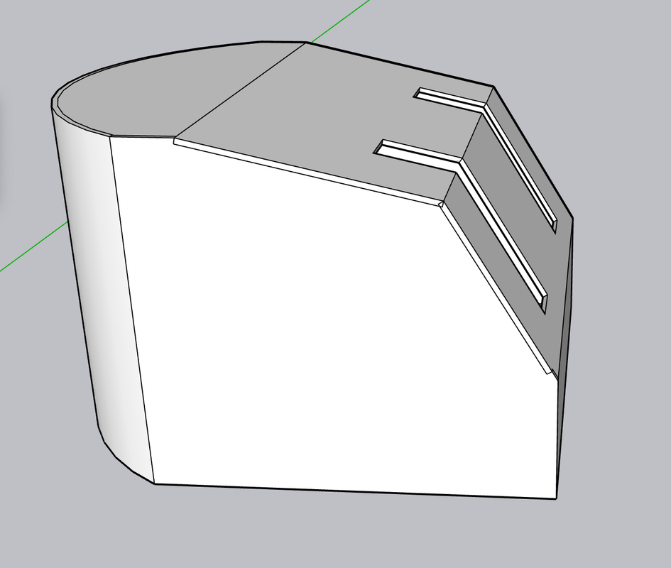
With my decision to go cold turkey and do it all from sratch, design work has begun in earnest. While I don't have fully dimensioned drawings for everything, I found another manual that fully details every aspect of the twin turrets and gave me enough specifics about the Mark 28 so I can get many important things right. As a result, I have fully TYdrawn to exact specifications the armored gun house.
The Mark 28's armor thickness was 2". That's 0.040" in 1:48, so using that sheet thickness, not only is very workable, but is correct scale thickness. I didn't have the luxury with the big gun. In 1:72, the 1" wall partitions would have been 0.010" sheet which is too thin to be practical. On the Mark 28, the armor plates are attached to internal angle braces by countersunk bolts and rivets. I was incorrect earlier when I said it was welded. There are a few exposed bolts where the floor framing members tie into the walls. Also I'm striking out finding pre-made 14" drop rungs wirh bolt rings. I already printed them for the big gun and can use the same drawing scaled up to make them for this one. I they held together at 1:72, they'll do well at 1:48.
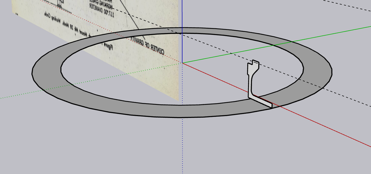
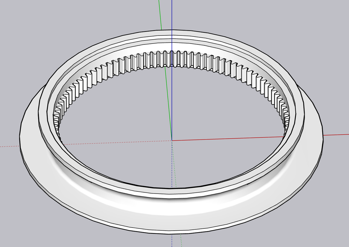
I have actual diameter measures of the base ring and training gear so I chose to start here. I also have a section drawing across the ring which I scaled. I placed the profile on a ring that corresponded to the base's overall shape.
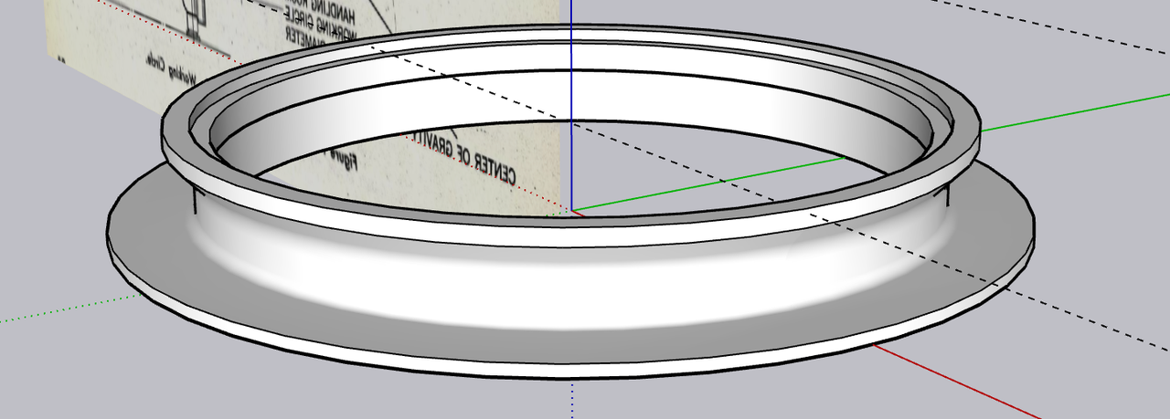
Using the "FOLLOW ME" tool (select the ring, select FOLLOW ME and then select the profile) and the program magically lathes the profile around the circumference. The counterbore and the land represent the lateral and tapered roller bearings on which the rotating mass revolves. I'm not going to detail the bearing. Unlike the monsters in the big gun, these would be almost indistinguishable in 1:48.
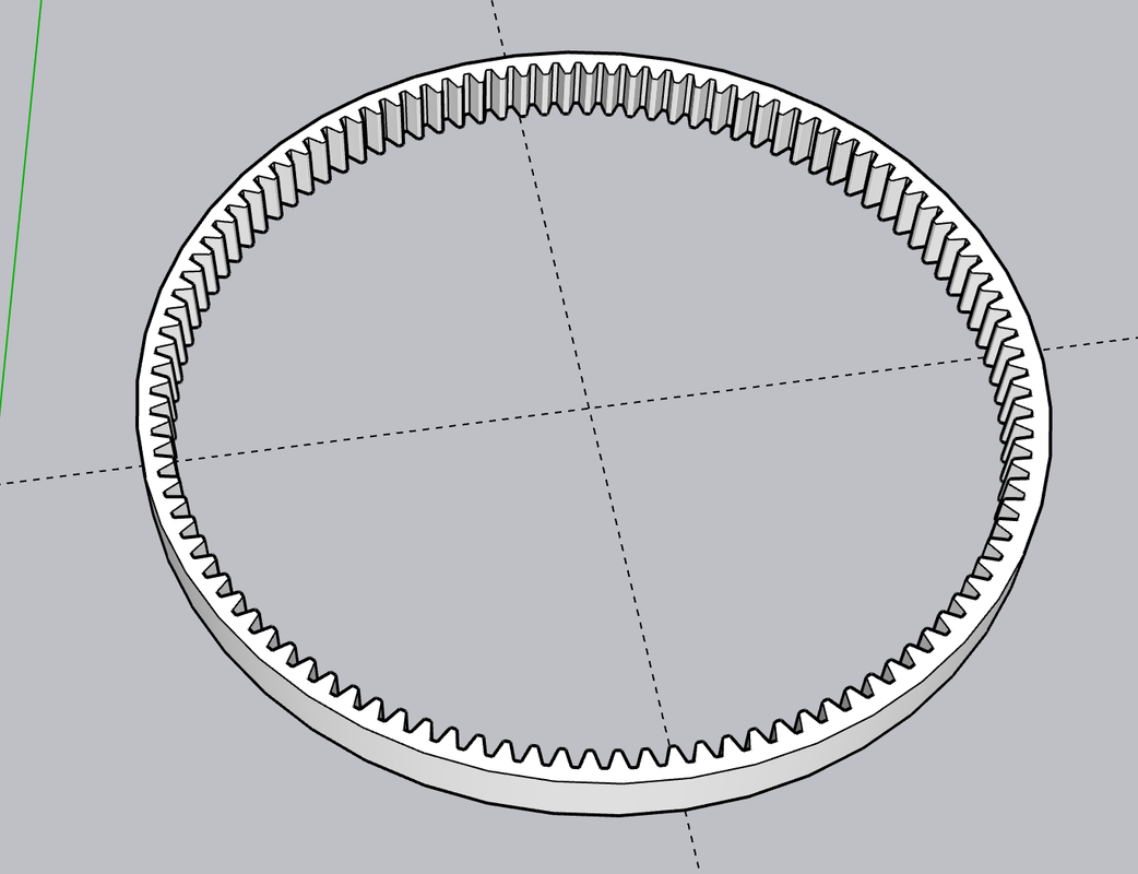
I learned how to do internal ring gears in building the big gun, but I'll quickly review it. I have an add-in to make volute gears. You enter the number of teeth, the pressure angle, and the pitch circle radius and Voila!, it draws a gear as a separate item. It only draws external pinion gears, not internal ring gears. I was able to find the exact number of teeth and the pitch circle diameter of the Mark 28's, and with those numbers drew the external gear. I also had the outside diameter of the gear which was the inside diameter of the bottom counterbore. I centered the external gear over a filled circle of the outer diameter and INTERSECTED the faces. I now had a drawing of a filled circle with line drawing of the internal teeth inscribed on it. I delected the inside, and then PUSH-PULLED the remainder to the height of the full gear as shown on my scaled cutaway drawings. All in all it took as long to do it as to write this paragraph.
I inserted the completed gear into the base ring.
The last things to do was add the reinforcing ribs and the nut/bolt/washer N/B/W images on the ring flange. I made one rib based on profile drawings and counted the number on the prototype. Looked like there we 32 of them. In SU, you use the rotation tool, with the center placed in the ring's center. You move/copy a single rib 11.2 degrees corresponding to the gap between them, and then key *31, the program copies the rest equally around the ring. It's "31" not "32" because you've already copied one.
I did the same thing with the N/B/Ws making a set of two and copying them around the ring.
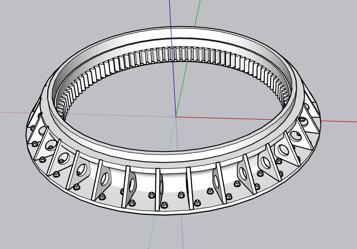
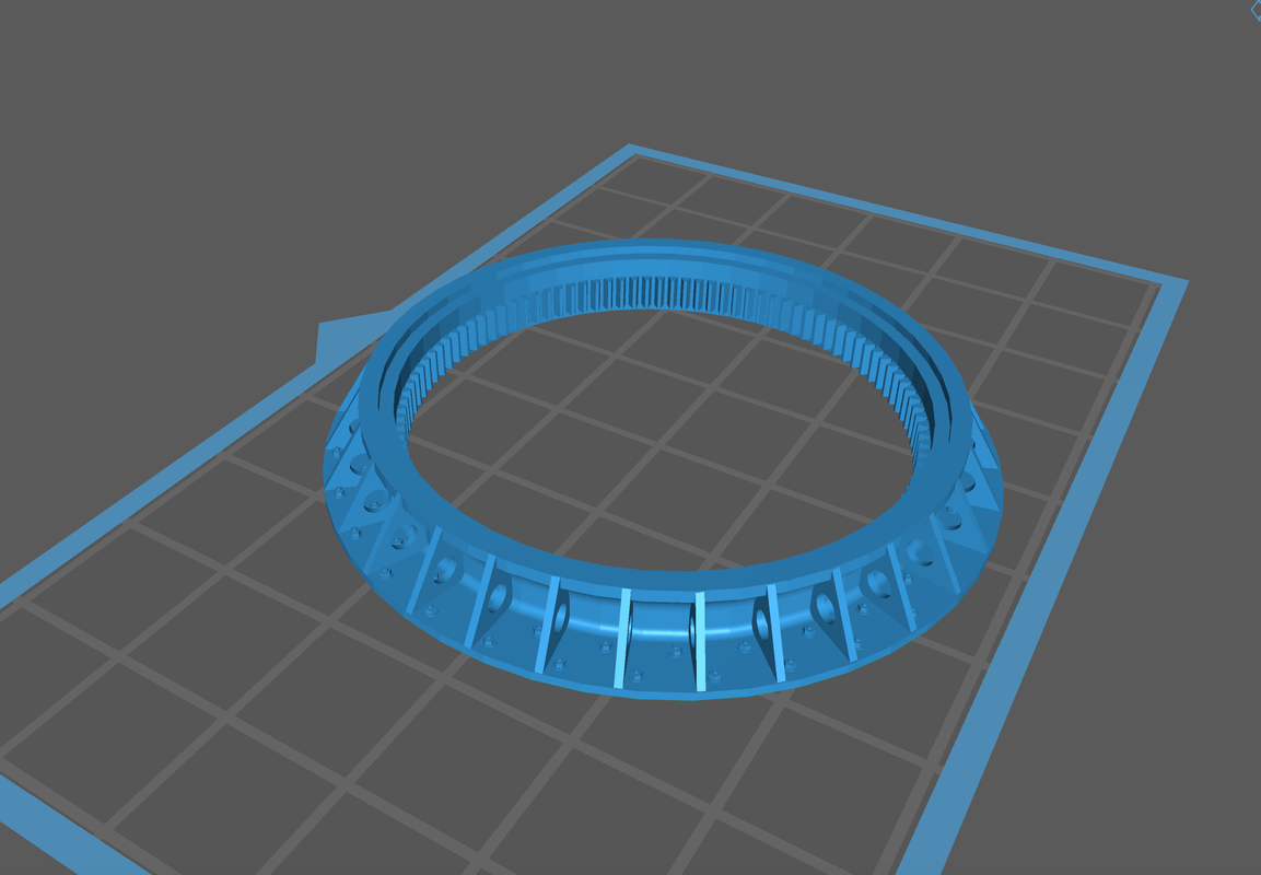
Because the geometry is so regular and one dimensional, I am going to attmpt print the entire part directly on the build plate. It will all depend on the build plate's ability to hold onto the part during the formation of the base perimeter layers which have the greatest amount of surface area. I those layers stay put, the rest of the print will be no problem. I will only take about 20 minutes to print, so I won't have long to wait.
If I was printing this part in 1/35 instead of 1/48, it would not fit this way and would have to tilted. Without tilting, there are no supports to deal with and details come out perfectly.
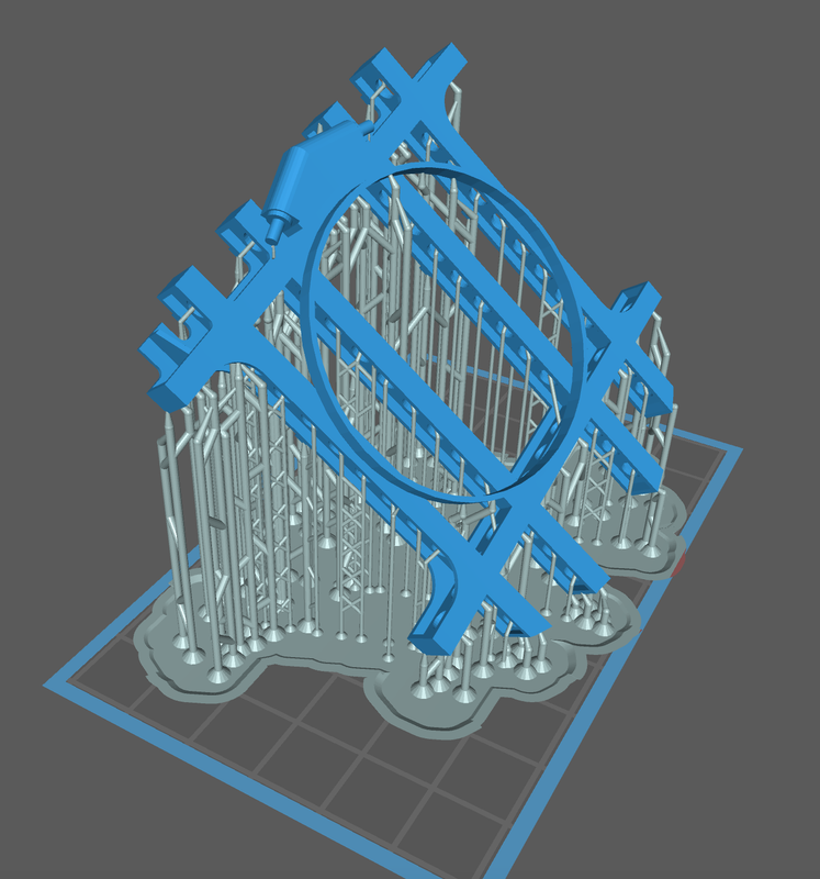
With accurate overall gun house enclosure dimensions and wall thicknesses, I was able to adjust my frame drawing so it was exact. If I was using the kit, I would have to wait until I could meassure it directly before finalizing the frame. I also had the exact diameter of the ring that connects the rotating to the fixed structure and attached it to the frame. I moved the training buffer inboard of the frame extremis to conform to the Mark 28 configuration.
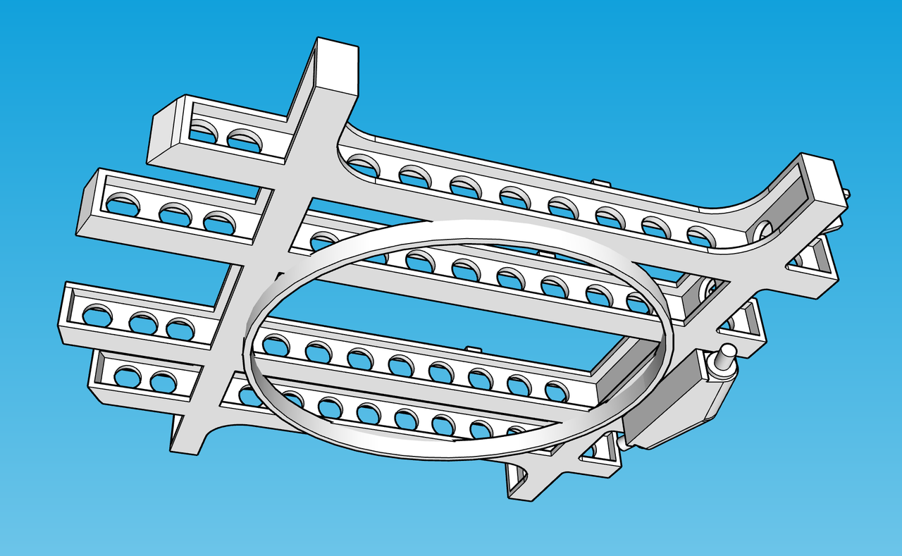
Again, in 1:48, this fits the printer nicely and will be a single part. This ensures perfect alignment of this important structure.
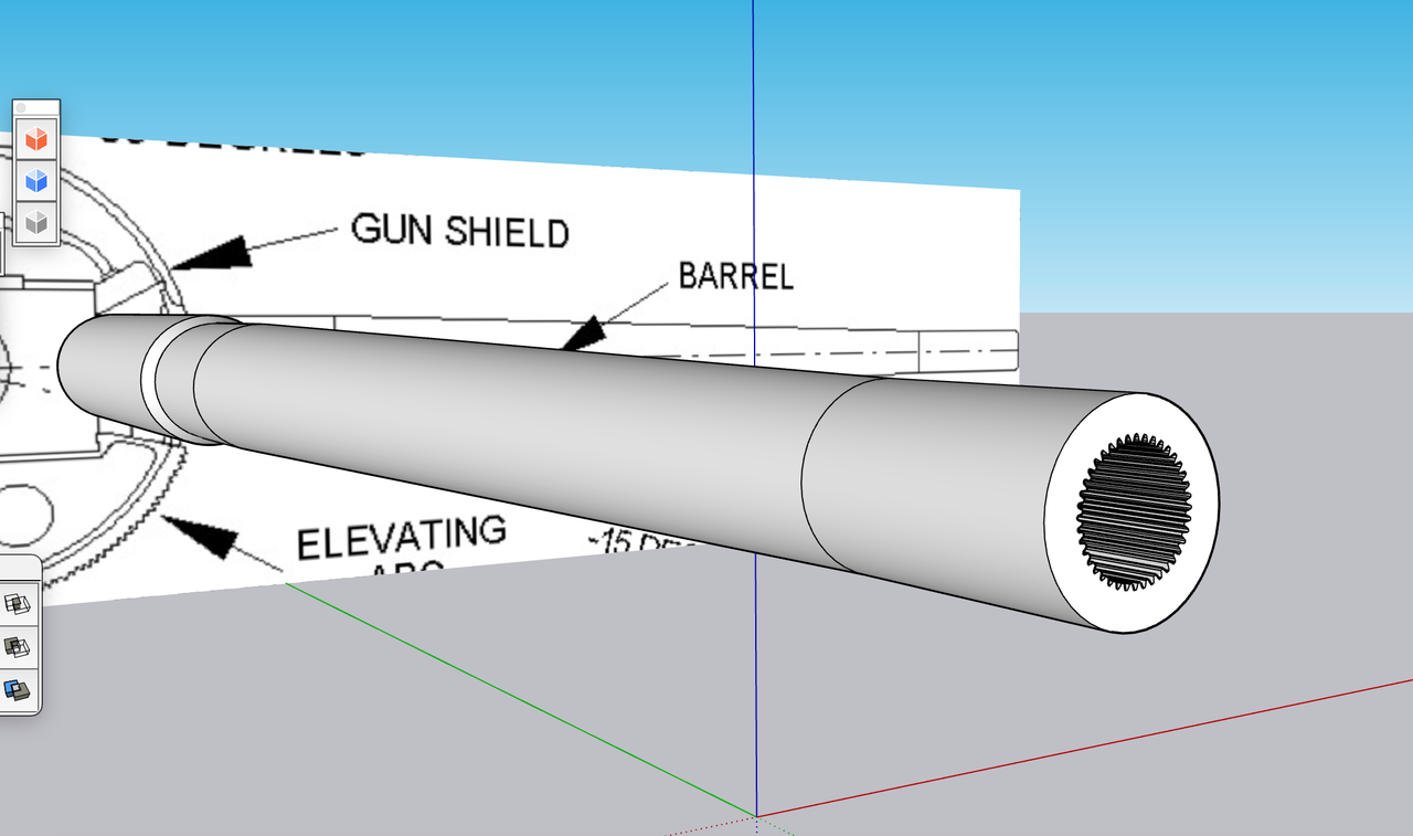
Last part I detailed was another critical one; the guns. I had good profile drawings so I was able to create the correct straight and tapered portions. I added some rifling. There are 40 lands, but did not add any twist. You're only going to visualize the very outer edges of it. The outer lip of the muzzle is rounded. I will do this as a post-print operation.
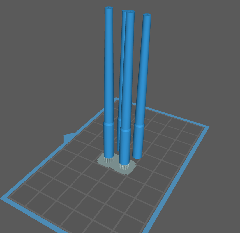
I'm trying two print schemes: Directly on the build plate and raised off. Since it's so symetrical, it can be printed straight up with no overhangs or islands. While it should print directly, I'm thinking that raising it will facilitate liquid resin draining from the bore.
We'll see which one wins. Unlike the ring gear which had little height, the guns will take over 6 hours to print. In LCD resin printing height is the key varialble in print time.
I found excellent elevation views of the all-important gun mount castings and will tackle them next. Also found good information about the complicated projectile hoists.
I actually need more information about the floor plan of the projectile handling room and the powder and projectile magazines on the 3rd deck.