So, taking it from the second to last pic...snip your plastic card to shape and sand down your edges so that it will be received by the main strut. I've even CAed a piece of brass rod (0.10 -I think...it's very tiny...essentially wire) to act as a visual aid as a strengthening element that's present on the real thing. The aluminum tube (that's just what I had lying around for the size I needed) I filed the end to bevel it so it is received by the rod surface that it will be glued to. I used a thin strip of a brass sheet but plastic card would work just as well for the turnbuckle that accepts the pneumatic tube for lowering/raising the assembly. Some tape takes the place of a slide tube since I didn't have the size and couldn't wait. I built up the shape appropriately and left the tiny gaps you see just so that I can leave a small drop of wash to give it some visual weight when painting. Otherwise you needn't bother with the extra cutting and what not.
The bulkhead that all of this goes into is visible up above. This was cut to shape and sanded until it fit. Again...more practical, less math.
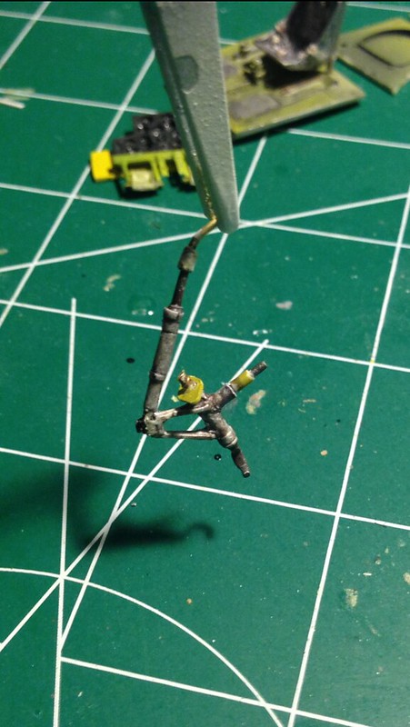 image by brittvallot, on Flickr
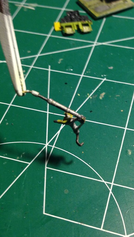 image by brittvallot, on Flickr
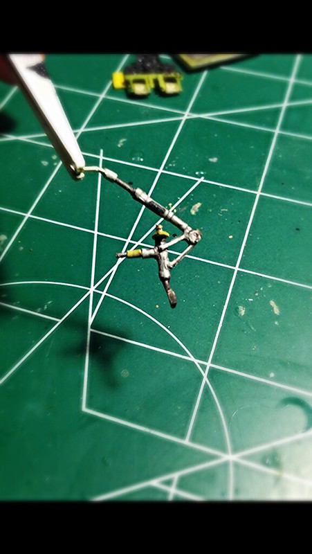 image by brittvallot, on Flickr
I've even gone and painted the placard for use on this bad boy. Too bad it's now invisible.
Next, I built up the structural elements of this back end. Most of this will not be visible by the time you're done...I found out later that practically none of it was. =[ Which was part of the reason why I wanted it done...but anyhow...I now have one incredibly strong tail gear! =D
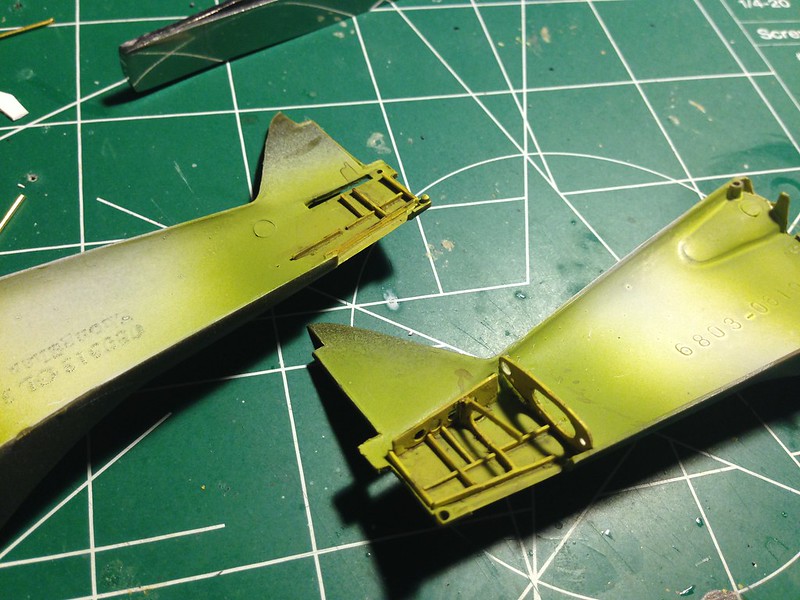 image by brittvallot, on Flickr
 image by brittvallot, on Flickr
Quick view from the bottom to see how this will come together:
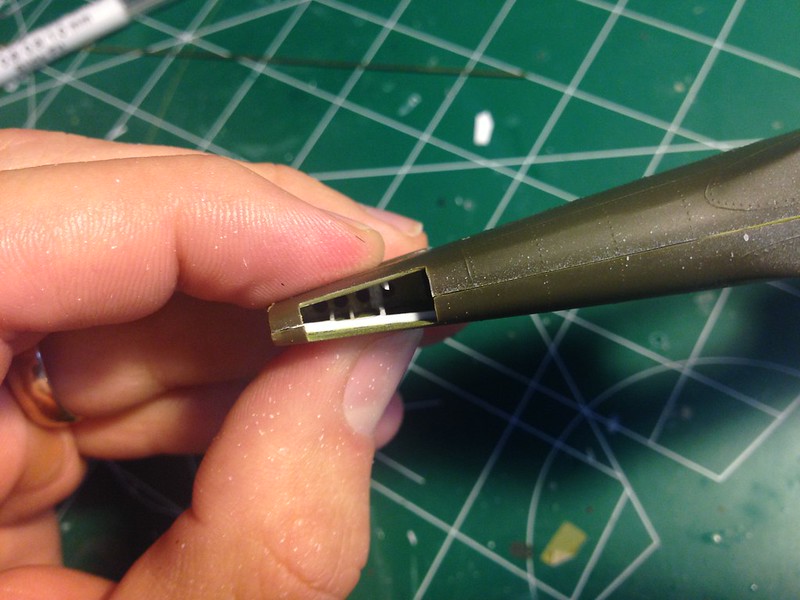 image by brittvallot, on Flickr
This picture is just to give you a comparison of these two parts in relation of the cockpit items. The part on the left will fit just below the space on the kit that accepts the elevator stabs.
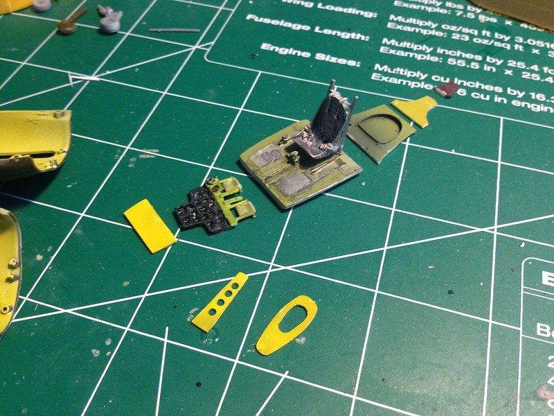 image by brittvallot, on Flickr
When it's all said and done, I think it comes out nicely and will definitely help to add some eye candy in some unexpected places. One nice thing you can do is to position your gear so that the tire is turned left-right if you're interested in showing the plane pivoting off a taxi lane.... just saying. =]
Moving on to the Cockpit:
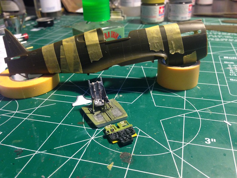 image by brittvallot, on Flickr
[Edited]
There are a few extra parts needed to scratch out to get all this to fit inside the Revell fuselage. When noting the bulkhead behind the seat, you'll find you need a piece above it to fit into the gap below the headrest area. You'll have to first sand the kit headrest off. Next, I've eyeballed the shape to cut in plastic but a better way might be to trace this shape out on a piece of paper and transfer it to the cockpit bulkhead and go from there. When laziness fails me I often fall back onto this and make a paper pattern to use for cutting out my shapes. This piece will rest snugly between the top of the seat and kit part below the headrest.
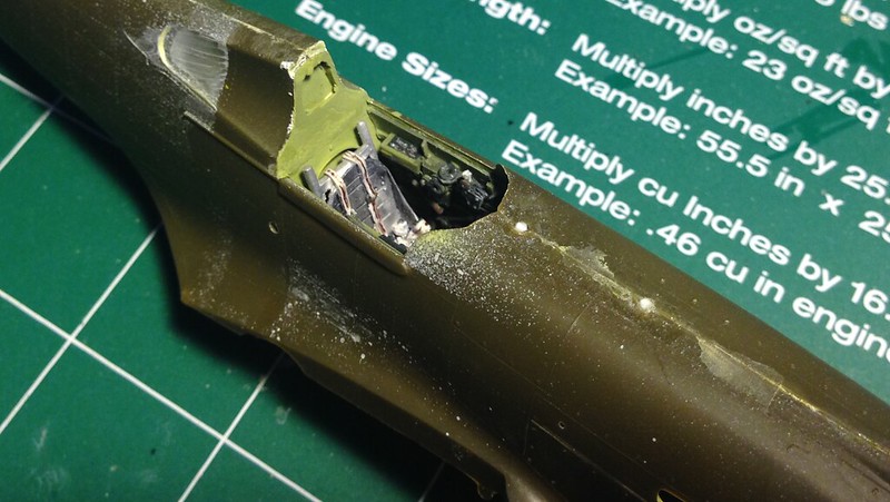 image by brittvallot, on Flickr
Here it is from the back:
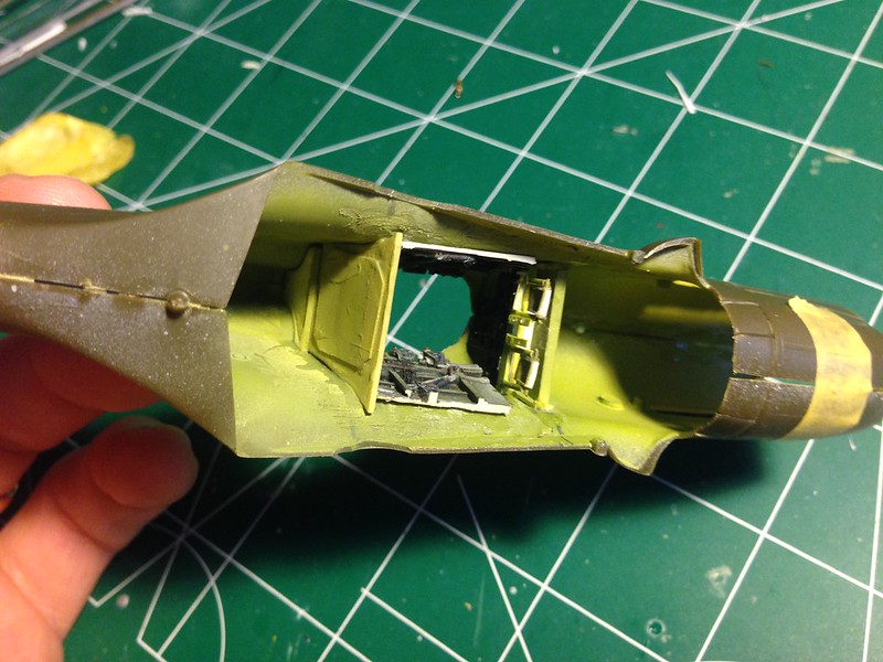 image by brittvallot, on Flickr
That will take care of the gap behind all of this. Some patient sanding will get it in there. There is the matter of the part up front (which I'm pictureless of now it seems) that leaves the gap between the TD part behind the seat and the headrest part from the Revell kit. Same thing...just measure you out the shape and carefully sand just enough to have it fit. I primed this part and used CA to fill it in and take care of any gaps.
For the IP, I've basically just made two "shoes" that fit vertically along the back piece of the IP that it rests upon. The "shoes" were sanded just enough to reinforce the fuselage and make it strong without pushing it out. Be careful not to spread it. This kit has enough issues as it is! =D
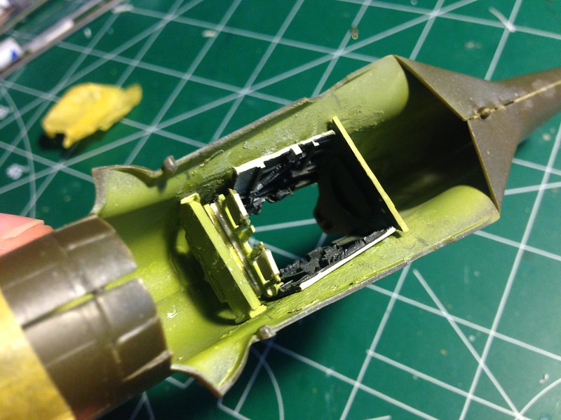 image by brittvallot, on Flickr
Here's a couple of interior shots of what this all turns out like
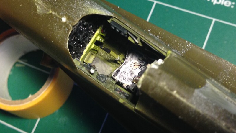 image by brittvallot, on Flickr
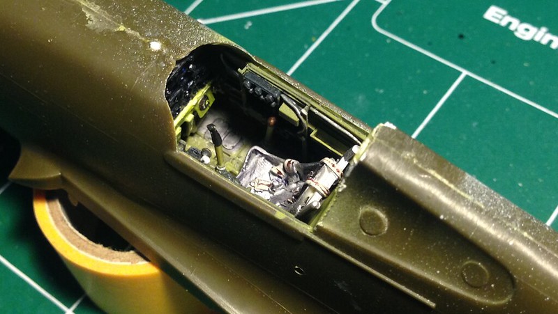 image by brittvallot, on Flickr
There's still the 50 cals to add...but that can come later.
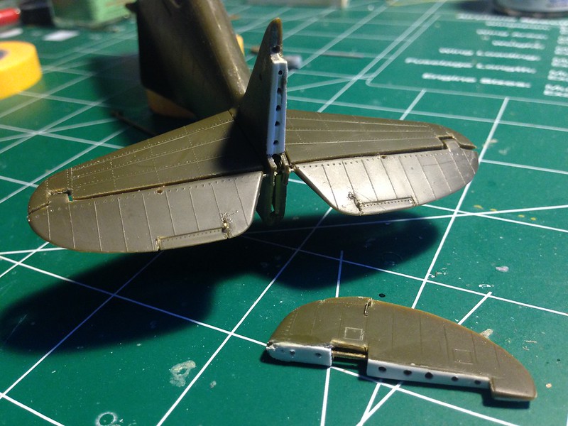
Back to the Tail. I wanted to get this part started and out of the way so it doesn't feel rushed later in the build when you are looking to get everything primed and painted. I started with taking care of the ejector marks on the bottom of the stabilators/elevators. CA sanded down and a needle tool to redo the rivets lost. I've also taken a razor saw and cut the elevators off so I can position them how I want. From photos it seems that the stick gets shoved forward a bit for the pilots to get out and most P-40 Bs seem to have the elevators pointed down. The rudder has the trim tab cut to make it look more like a separate piece and a hole drilled to allow for a stronger actuating rod for the trim control. The trim on the elevators are cut as well and will be dressed up also.
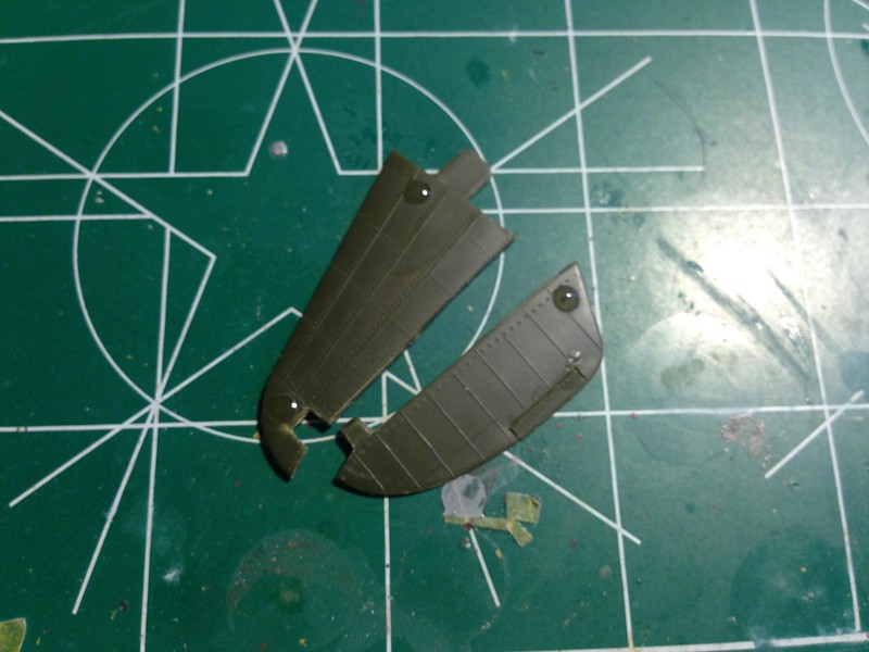 image by brittvallot, on Flickr
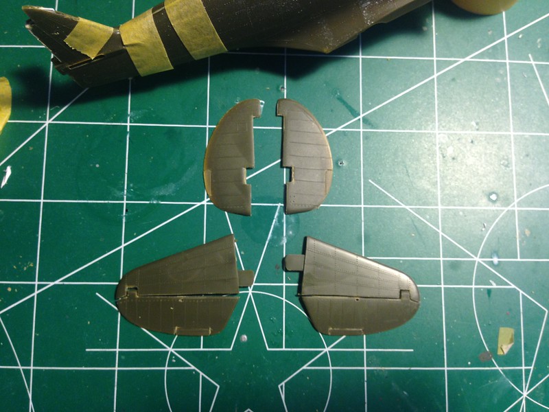 image by brittvallot, on Flickr
For some extra detailing, there's a hole (appearing to be an access point to view) for the rod working the controls for the elevators. Drilling this hole horizontally all the way thru is ridiculous and next to impossible at this scale, soooo...I've opted for the "appearance" of what should be there.
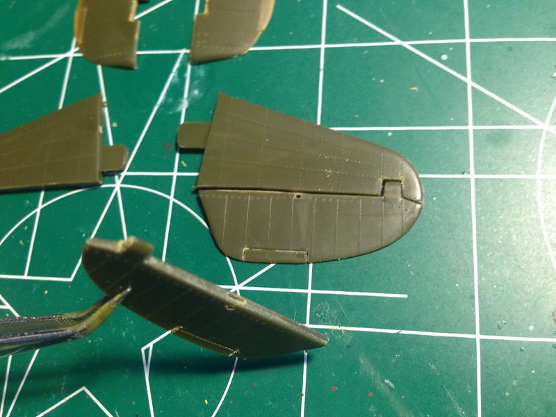 image by brittvallot, on Flickr
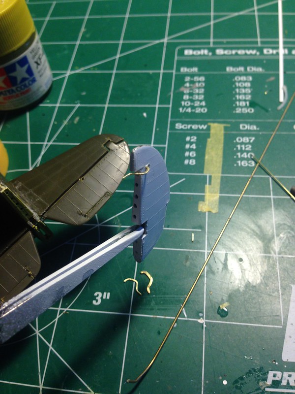
Shaping the Rudder Horn:
This is from a brass rod that is bent to shape and then flatten with the flat edge of my needle nose tool. The same could be done by sanding with some metal files, but I imagine it'd take a LOT longer.
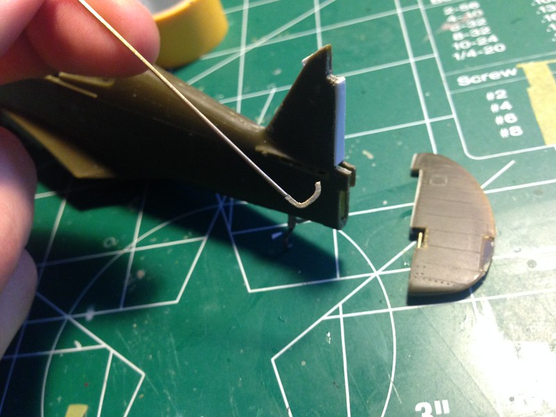 Untitled by brittvallot, on Flickr
Trim tab control:
By drilling this hole first and fitting the tiny brass rod (basically wire) you get more rod inside and behind so that it can be CAed down more effectively without breaking. Very handy bit of info right there.
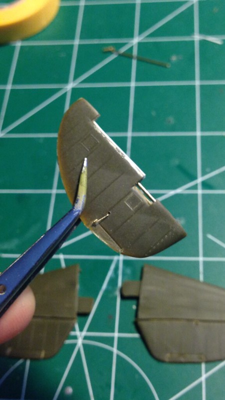 Untitled by brittvallot, on Flickr
I also fixed up the backing so that matches up to the vertical stabilizer.
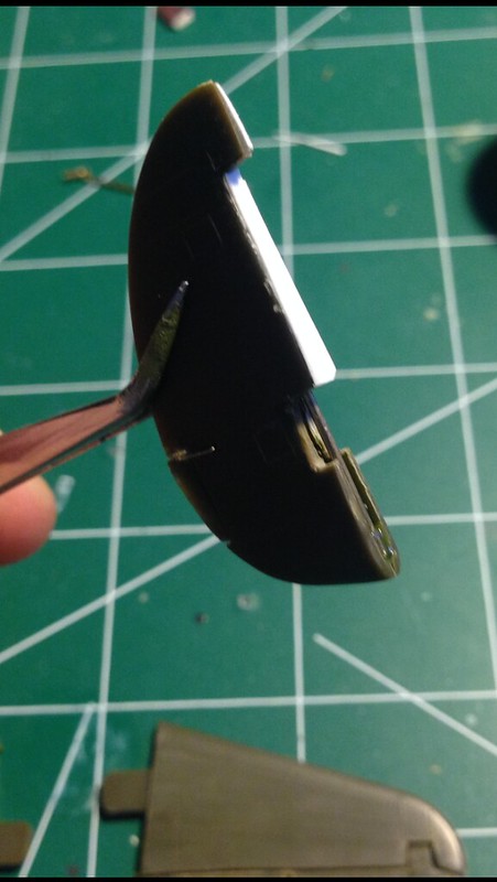 Untitled by brittvallot, on Flickr
 Untitled by brittvallot, on Flickr
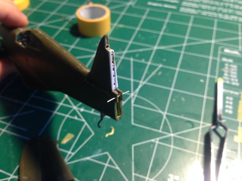
Here I've done the same with plastic card, except I've used a thicker piece so that I can sand down the middle to create the interior and drill my holes. Just a simpler way with less glue and less fuss. And less cutting!
The rod going across horizontally is to the elevators and as it happens it better supports them as well since I've cut them from the stabilators.
[Edited] I also went ahead and cut this rod after fixing it to the tail. The vertical rod working the rudder will end up fitting just inside of this part. Since I wanted to paint some of this before fixing it to the rest of the plane, I opted to snip the horizontal rod as they are short enough over themselves to remain strong and still support the elevators.
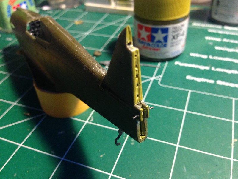 Untitled by brittvallot, on Flickr
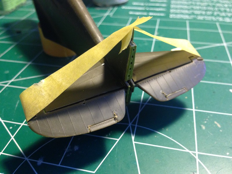
A little paint and...a test fit.
 Untitled by brittvallot, on Flickr
 Untitled by brittvallot, on Flickr
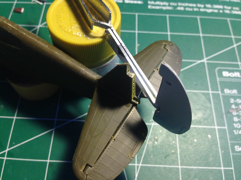
Taped to insure their fit. The locating pins do some good at securing the stabilators onto the fuselage. My first time around with this I believe I sanded these off by mistake. I found a much tighter fit this time around. Still, not taking any chances...I taped them up to keep them where they belong while the CA and Tamiya Extra Thin Cement set up.
Viola!
 Untitled by brittvallot, on Flickr
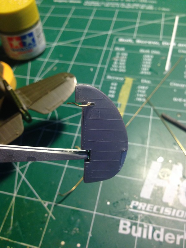
Back to the Rudder Horn:
 Untitled by brittvallot, on Flickr
 Untitled by brittvallot, on Flickr
Take your time fitting this to the tail. A small hole is necessary to drill into your plasticard patch up. Double check your dry fitting before committing.
That's that for now. I realize I've glossed over quite a lot for some. If you have any questions about a specific step, please don't hesitate to ask or PM me about it.
=]