I had this all written up last night but got distracted and so didn't get around to posting it. Work started on this in the evening since there wasn't anything particularly good on TV, and began where it normally does with Step 1 dealing with the sprockets, idlers, and road wheels.
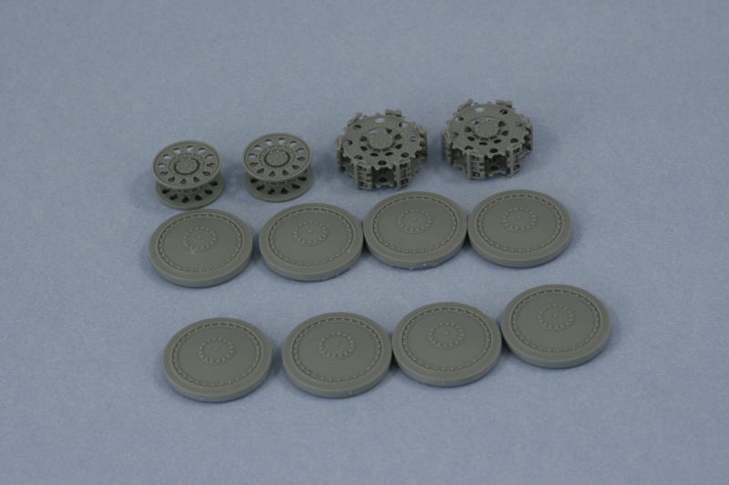
Each road wheel was removed from the sprue and has 4 connection points and a largish seam that needed to be sanded down. I used a flexible sanding board to accomplish this, one wheel at a time. The step instructions appear to give you an option of using two different types of sprockets and idlers but only one type is really correct for the Grille H. That's the "early" type that have holes in the sprockets (parts A3/A4) and the tear-drop shaped holes in the idlers (A5/A6). The sprockets in particular have difficult sprue attachment points, some so close to the guide teeth that they are almost integrated, so I cut them away from the sprue with enough of the stub remaining to allow their removal with a sharp knife vs. using sprue cutters for that job.
The sprockets are a two-part assembly with a small locating tab designed to help insure correct alignment but the tab is smaller than the socket so there's a little bit of play there. This can cause the sprocket teeth to not align properly which of course will cause problems when fitting the tracks, so I used 6 links of loose Magic tracks to insure that the sprockets were properly "gapped" to allow clearance of the link guide horns as well as proper fit and alignment of the teeth into the links. The track links were evenly spaced around the sprocket and left in place as the glue dried. The idlers also use interlocking tabs, 2 instead of 1 like the sprockets, but these are also loose so care is needed to insure they too are properly aligned when installing.

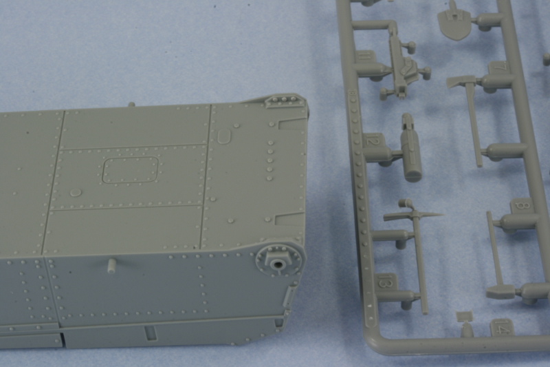
The next little item was the addition of 3 bolt heads to the lower hull brace for the idler mount. The bolt heads come on sprue K and have to be carefully sliced off and then glued into position on the lower hull. Not something that will be readily seen on the finished build unless you flip it over, but it's there for the curious.

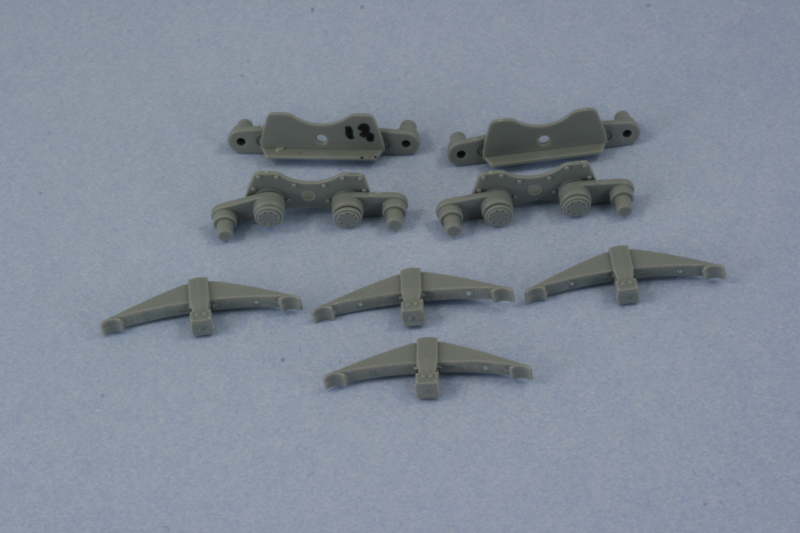
Continuing on with the suspension, the sub-assembly step that constructs the bogey mounts was assembled. The diagram here is a bit misleading...it seems to indicate that you can add the springs to the hull mount plate but that actually isn't possible until Step 6 because the post that the spring would attach to is molded onto the lower hull. The little gray arrow that points to the hole in the plate is marked as not to be glued...which doubles the irony because there's nothing to glue it to anyway! You are presented with the option of using either springs with the open slotted cover or the solid cover, the solid cover is the correct type as the slotted covers were used primarily on the early gun-tank versions while the solid cover was a later style. For those interested in super accuracy, both spring types feature 15 springs when the slotted cover type should only have 14 per the descriptions in Panzer Tracts No. 18. I attached the swing arms to both plates and carefully glued in the caps so that the arms would remain movable. This will help insure the road wheels sit level later on when they are installed. Since Step 6 is a long way off, I used a permanent marker to mark the two A13 plates since the instructions indicate it's important which set goes on which side.

Total session time: 2.5 hours
Total time to date: 2.5 hours