SEARCH FINESCALE.COM

Enter keywords or a search phrase below:

Meng M2A3 Bradley w Busk III and Full Interior: State-to-Finish Build

30783 views
115 replies
1 rating 2 rating 3 rating 4 rating 5 rating
  • Member since
    March 2012
  • From: Louisville, KY
Posted by Builder 2010 on Saturday, March 6, 2021 9:45 AM

Ugh! The worse thing that happened to me working on those M113s was attempting to remove the lifting lugs from the roof. I has sitting on the top with my feet hanging over the back and pulling on a very big wrench. The torque on the lug bolts was very high. Instead of loosening the bolt, my force threw me off the roof. It's Newton's law, "Action/reaction". It like loosening a bolt in zero G. I was lucky, I landed on my feet and was quite surprised, but unscathed.

Finished my income tax paperwork which took some "work" time today. 

i finished all the interior items so the next step will be to glue on the lid. I went a little bit crazy. I created periscopes that actually work... sort of. I had to cut masks for the optical faces so they wouldn't be painted, and then added some Bare Metal Foil to the angular reflecting faces so 'theoretically' the optical path should work. 

I made a slight booboo by removing the mask on the wrong end. Since the interior was already painted I surmised that I could take off that mask. Only I removed the exterior optical face's mask. These units need gluing in BEFORE the lid goes on so the optical faces would be exposed to future exterior paint. Instead of cutting and applying little tape pieces, I just used MicroScale Liquid Mask. That's why when I took a picture looking trough the periscope, you see the blurry blue light. It's shining through the liquid mask. But it is reflecting light from the other end of the periscope.

You won't be able to see much of this marvel with the periscopes installed since we're not 1:48 sized people looking into the periscope's interior end, and there won't be a light source inside to be visible from the outside. But I know it's there.

Here's the full suite in place.

I glued the driver's LCD in place after placing decals and gloss coating.

There's a bracketed unit hanging into the engine hatch that seems to contain a cap probably for engine coolant. It has two small decals on the front curved face, and these needed multiple applications of decal solution to finally get them to curve down and around. I almost lost one of them in the multiple adjustments to get them straight. This needs to be dullcoated.

I painted the seat belts. One of them, noted with the arrow, had a mold failure and can't be used (or I could splice some tape over it and use it... just thought of that). 

The last things to add (not yet painted) are the trans linkages for steering and gear selector. It's nice that these two critical and fine details are added. Mechanically, the Bradley seems pretty well designed. I imagine the shift over the years from brake bands to control skid steering to automatic transmission clutch packs was significant in operational stability.

And finally...

Last night my wife and I shared the wonderful benefits of both being vaccinated and reaching the 14 day maturation period. We had dinner at our daughter's. She and her husband are both fully vaccinated. We were able to hug. Sit with people and talk without masks. Saw the face of my grandson, who, although not vaccinated, has been recently tested. The chances of contracting the virus when fully vaccinated is very low, and now we're finding that the odds of transmitting it are also as low and contracting. He's approaching 17 and his face is changing and we were able to see the difference since it's been months since we saw anything but his eyes.

The other great thing about the shots is it instantly removes the angst you feel when out in the public. You no longer have to freak out if someone is too close to you, you are interacting with someone who's wearing their mask below their nose (or below their chin), of it you touch something and touch your face without using hand sanitizer. You won't get sick from this any longer, or if you do get something, you won't end up in the hospital on a respirator or die. Since I'm 75 and have AFib, I wouldn't do well with Covid.

When you get the chance, get the shots!

  • Member since
    December 2002
  • From: Valrico, FL
Posted by HeavyArty on Saturday, March 6, 2021 7:49 PM

More great progress.  The vision blocks look good, however, modern ones are not clear, but have a reflective anti-laser coating to protect the crewman from eye injury if a laser is pointed at the optic.  They vary in color from red to purple to blue to gold, depending on the angle.  I replicate them by painting the optic black, then a couple coats of clear red, and finally a couple coats of clear gloss.  It looks good and also varies in color from different angles.

You can see the color on the driver's vision blocks on the M7A3 B-FIST (Bradley Fires Integration Support Team - artillery observers) vehicle below.

Gino P. Quintiliani - Field Artillery - The KING of BATTLE!!!

Check out my Gallery: https://app.photobucket.com/u/HeavyArty

"People sleep peaceably in their beds at night only because rough men stand ready to do violence on their behalf." -- George Orwell

  • Member since
    March 2012
  • From: Louisville, KY
Posted by Builder 2010 on Monday, March 8, 2021 5:46 PM

That's a terrific picture showing the periscope tint, but also giving a pretty good cue on the desert yellow paint. It looks like a BUSK with the ERA not installed on the clips.

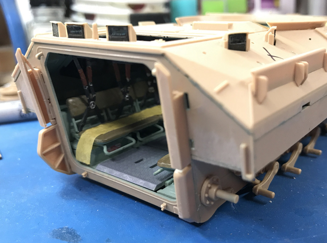
I got the hulls top and bottom joined and then realized that I hadn't installed the seat belts. Luckily, you can, carefully using a tweezers, install the belts when the top is glued on. Gluing the top was pretty straight forward, but did require a little cajoling to get the left side to seat down properly. I used tape and some clamps to get in settled.

The arrows on these images show the critical joints that needed attention to make sure they were seated properly.

This one was troublesome. The upper hull had a secondary lip that needed to lock behind the lower edge. I really needed to add some extra muscle to get it seated. It all gets covered by the ERA armor panels.

I started working on the armor and upper surface detailing. This includes adding lifting eyes and other appliances that make the complex surfaces come alive. This included some PE. I tinted the slats only to find that the PE grill that went on top obscured everything below it.

The PE grill and another piece of PE that goes on the lump next to the turret opening. I suspect, the turret's going to make seeing that piece of PE impossible.

Like I noted in the preamble, I missed attaching the seat belts onto the top hull before their joining. The belts cement into a notch in the top. I was able to get them in using tweezers and gel CA starting at the most forward ones and working back. I was also able to rejoin that badly molded one using some masking tape as a backing and some Gel CA to fill in the gap. There's absolutely no load on these parts since they just drape behind the seats on the bottom so my masking tape solution is just fine. That tape strip on the seats is keeping the rear door actuating lever from falling out before the door is in.

And then I ran into a snag. One of the add-on armor panels was part Q3. So where the heck was sprue Q??? I didn't have a sprue Q. I never had a sprue Q. Sprue Q is missing!

I knew that space was blank on my rack from the getgo, but there wasn't a sprue 'O' either so I didn't pay it any mind. Until today, that is. This was the first part off of that sprue. Sprue Q's a big deal with all the sub-based for the ERA.

I found the eMail address for Meng Models Customer Support on their website. I followed the instructions and sent them an eMail explaining the problem. Within the hour I got a response from China requesting some more information. I am sure that it will be rectified shortly. To date, my interactions with Chinese companies' customer service has been pretty positive.

Meanwhile, I was able to continue building things that don't require Q parts, but that will come to an impass further down the line. I'll let you know how this all works out. I finished out the day building the driver's hatch and masking and painting the smaller periscopes that are included therein.

  • Member since
    December 2002
  • From: Valrico, FL
Posted by HeavyArty on Monday, March 8, 2021 7:08 PM

Nice recovery on the belts.  The interior looks great.

Builder 2010
That's a terrific picture showing ... It looks like a BUSK with the ERA not installed on the clips.

The clips are actually multi-sided tie-down points for attaching straps to hold gear such as rucksacks, duffle bags, water jugs, etc...  They are removed when the ERA for BUSK is attached.  This M2A3 has the newer T-161 tracks too.

The ERA blocks are attched using "c" channels that attach to the same bolts as the tie-down points above. 

Each BRAT (Bradley Reactive Armor Tile) has tabs on the sides that slide down into the "c" channels.

These "c" channels are correctly molded onto the Meng side armor panels.


Gino P. Quintiliani - Field Artillery - The KING of BATTLE!!!

Check out my Gallery: https://app.photobucket.com/u/HeavyArty

"People sleep peaceably in their beds at night only because rough men stand ready to do violence on their behalf." -- George Orwell

  • Member since
    November 2020
Posted by Also known as Rob on Tuesday, March 9, 2021 9:42 AM
Late to the party ... but love the sprue rack.
  • Member since
    March 2012
  • From: Louisville, KY
Posted by Builder 2010 on Tuesday, March 9, 2021 6:14 PM

More good pics! Late is better than never...

Without sprue Q I was still able to continue adding parts. I am watching to make sure that I don't paint myself into a corner with a missing part that can no longer go in once the sprue is replaced. Places where "Q" parts go I'm marking with an "X" with a Sharpie to remind me that something goes in that place. This included finishing up the driver's hatch and adding a load of detail stuff all over the hull front to mid areas. 

The special driver's optics in the BUSK III version has a grill in front to protect it. I can't imagine what you're supposed to see when looking through that grill, but you must see something or they wouldn't do it. It's a finicky little build with a transparent part inside (which you can no longer see) covered over with that grill. I think the grill is removed for viewing. There's a mechanism in the front that might be the way it works.

Here it is installed along with the driver's hatch. I attempted to get a orange reflective surface for the periscopes. I didn't get it exactly right. I used the Molotow Chrome Pen to first make the lens reflective, but I should have sealed it with some clear (non-alcohol-solvent) lacquer because the clear red/yellow mix dissolved the Molotow and gave a muddier effect than I wanted. It's not easy to strip and do over since they're all mounted in the hatch.

My pre-treatment of the radiator grills yesterday was a waste of time. The PE grill that goes on top (another BUSK III variable) complete obscured what's below it.

The air intake grills I first painted rubber black and then added its PE cover. But this piece has bigger openings so you do see what's below it. The exhaust stack goes on the open area at the top.

It was time to fit the engine cover. I had glued in the prop that holds it open, but I want it closed during exterior painting so I carefully removed it. I doubt that my metallic lift pistons will work because their respective cylinders are not articulated so they would bind the piston rods as they attempted to move in and out because the piston rod angle changes through their arc of travel and the cylinders are fixed and wouldn't adjust. 

After romoving the support I was able to close the hood all the way. In this image, the hood hinges are not yet snapped into their pins. When I attempted to do so, the glue wasn't fully set and one of the hinges was trying to detach from the hood. I took the picture and it's drying overnight. This way I won't have to attempt to mask the engine compartment opening.

And here it is in the closed position still without the hinges fully attached.

Last thing I did today was assemble the exhaust stack parts and get just the stack install. the guard will go on after I paint the stack.

Here's the stack glued in.

Here's a better look at the orange persicopes.

It's a bit sloppy, but I will improve on it when the body is painted. I may strip it and do it over...

  • Member since
    December 2002
  • From: Valrico, FL
Posted by HeavyArty on Wednesday, March 10, 2021 7:27 AM

Nice progress.  It is looking better and better.

Builder 2010
...driver's optics in the BUSK III version has a grill in front to protect it. ... I think the grill is removed for viewing. There's a mechanism in the front that might be the way it works.

The optic is not part of the BUSK package, but a feature of the A3 upgrades to the basic Bradley.  BUSK (Bradley Urban Survival Kit) is all the add-on protective features such as the ERA blocks, commander's shield surround, and screens on the optics.  The screen is not removable.  You can see through it w/no real issues.  The little cover on the optic is part of the optic and folds up to cover it when not in use.

Builder 2010
...the radiator grills yesterday was a waste of time. The PE grill that goes on top (another BUSK III variable)...

The intake screen is not part of BUSK.  All Bradley's have this screen so debris doesn't get sucked into the radiator area.

Gino P. Quintiliani - Field Artillery - The KING of BATTLE!!!

Check out my Gallery: https://app.photobucket.com/u/HeavyArty

"People sleep peaceably in their beds at night only because rough men stand ready to do violence on their behalf." -- George Orwell

  • Member since
    March 2012
  • From: Louisville, KY
Posted by Builder 2010 on Wednesday, March 10, 2021 10:21 PM

You are a great resource and keep me honest!

Work continued on the hull top with the rear top hatch. This is going to be one of the two working hatches on the vehicle. The other is the driver's hatch. The engine cover and the rear access hatch are going to be fixed since the tiny styrene hinges are just not going to hold up. Already the engine hatch's left hinge is broken just in attempting to snap it together. 

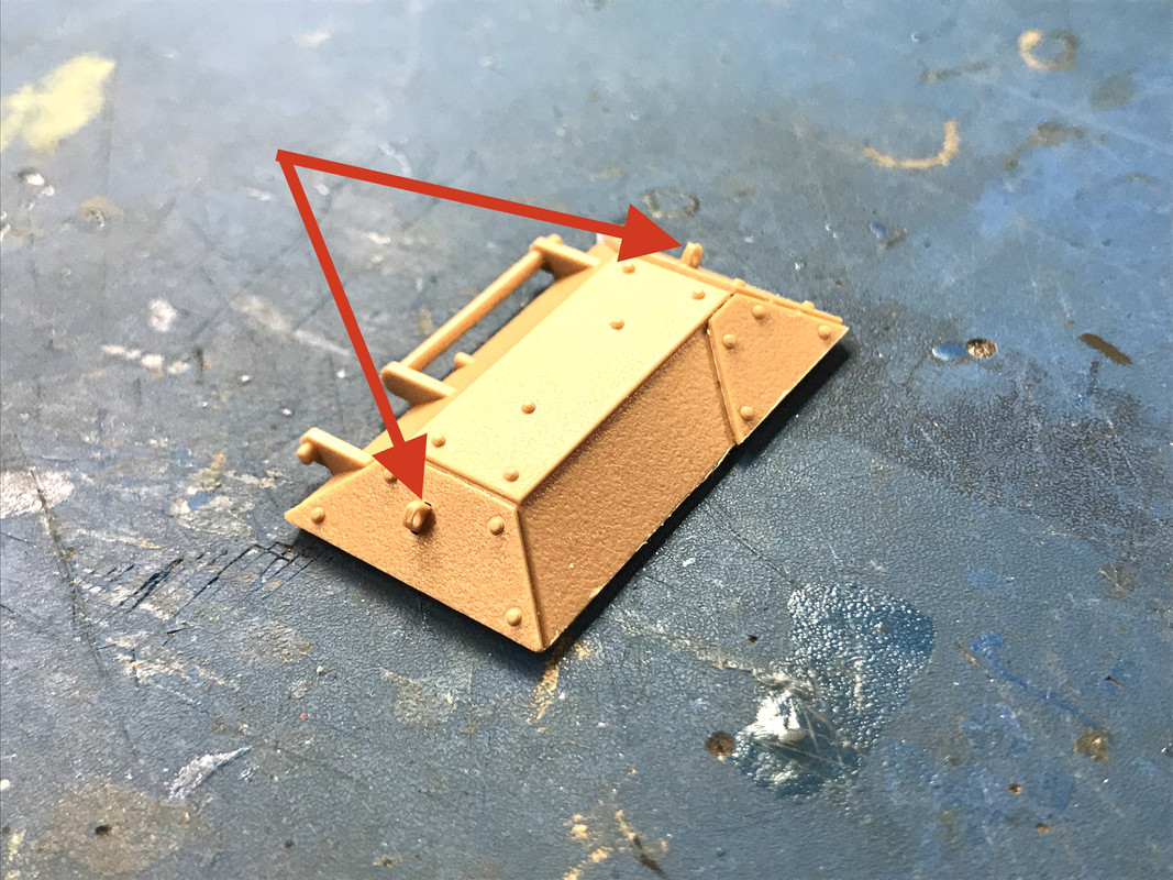
The top hatch has three pieces of add-on armor which I glued in only to find that there are two eye pads that needed to be glued in first. Luckily, it was just a short time after putting on the armor so I was able to break the glue joint without damaging anything, glued in the two eyes and put them back on. (arrows)
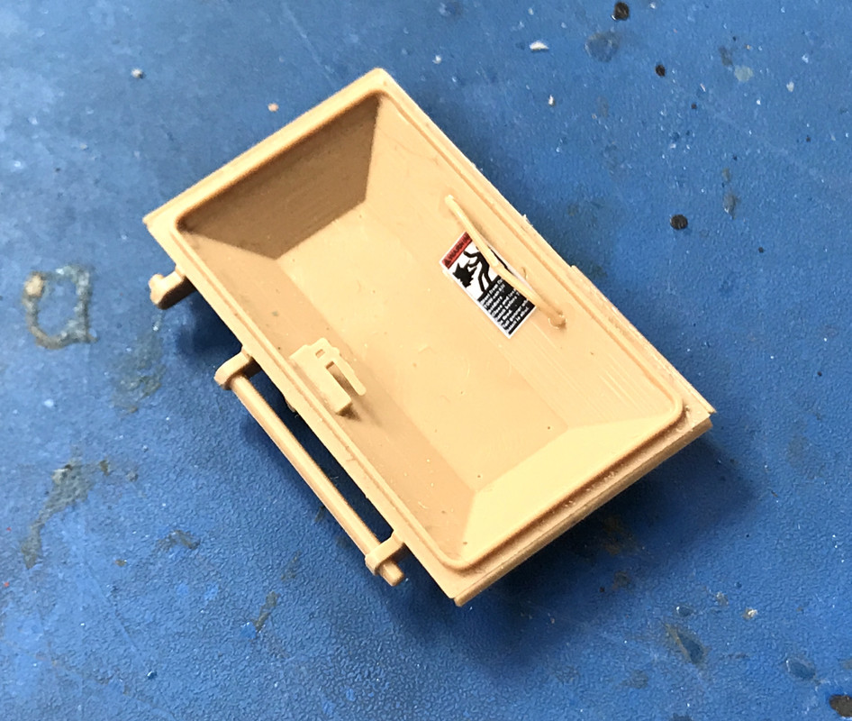
There's a latch and hand grab that went inside the hatch, and a decal. I'm not going to paint this interior since it's body color and won't be faded or badly weathered. I put the decal on now. I want this hatch closed when I paint the body so I won't have to mask the opening.
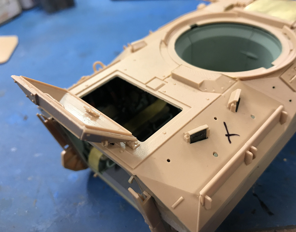
The two outer hinge pads are real. The center one is not... just for show. The hinge pins are robust and the hatch works well. The black "X" shows another "Q sprue" missing part space.
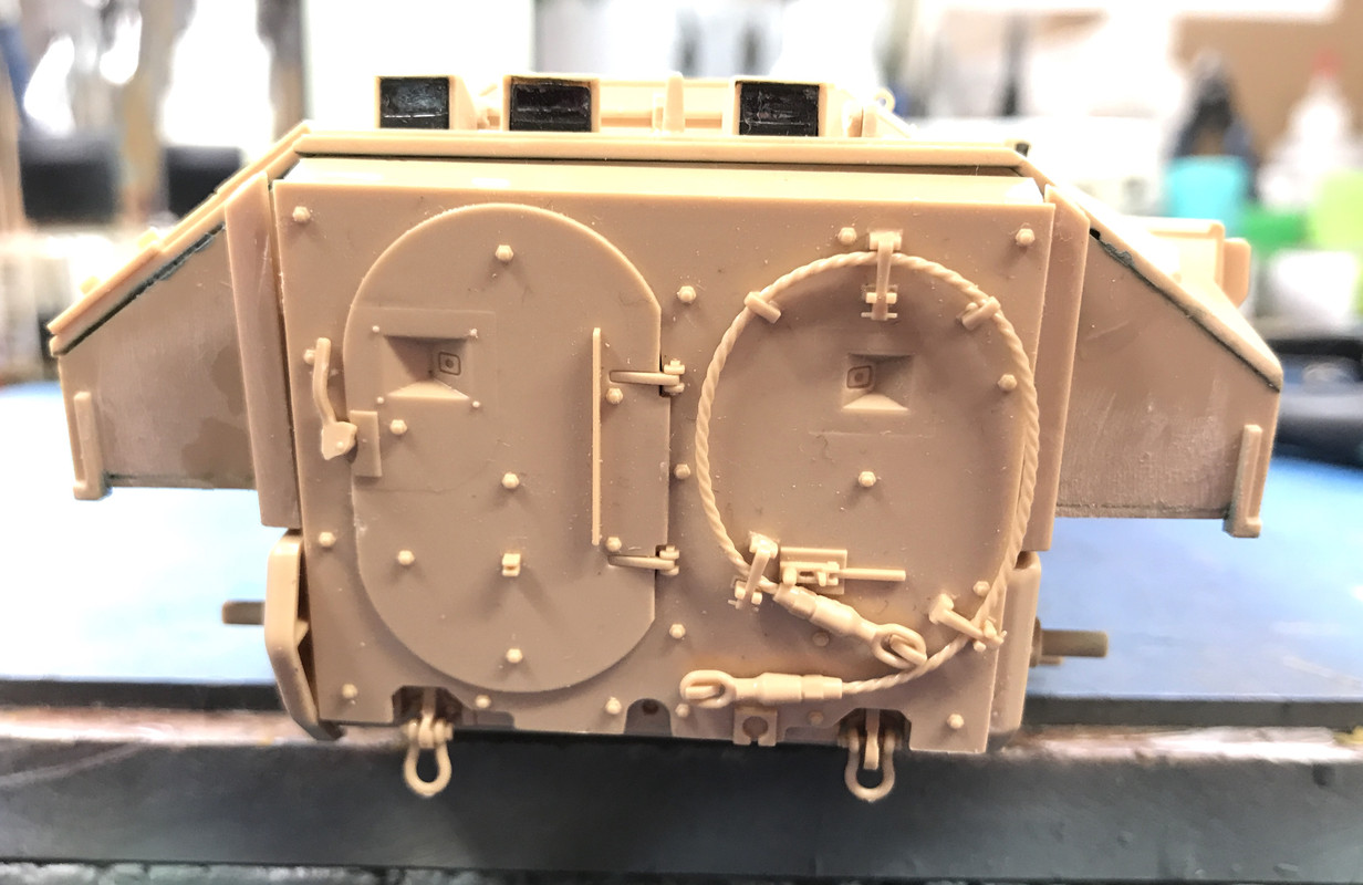
There's a bunch of assembly before the rear crew door gets installed. There's a link that ties to the actuating arm that I had to tape to keep it from getting lost. After you glue that in, you glue in the male part of the door's hinge. The other side is molded into the inner door face.
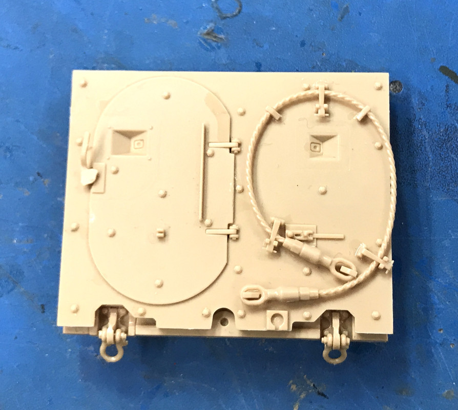
The detailing on the model is stunning!

The door jamb on the body had parts to install also. Notice the tiny female hinge components on the frame's bottom. They will break! Those are the kinds of parts that should be investment cast brass, or brass plate fabrications.
I was able to install the link and get the door in place and it will stay closed during painting. The tow cable had to get glued to the door's face. Do it now or later? It would be easier to paint off the door, but gluing it on would require touchup. So I decided that I would be able to paint the cable on the door without making too much mess.
I masked the turret hole and with that, the body is ready for the paint shop.
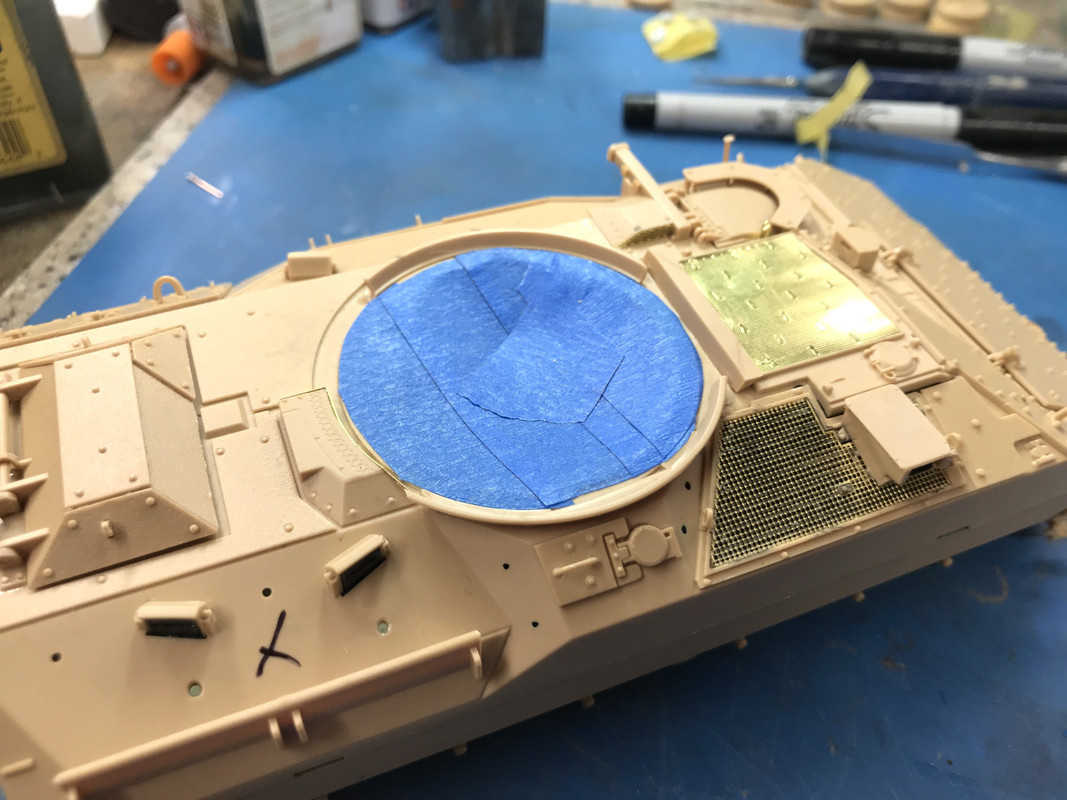
Can't paint the body until the rest of the "Q" parts get done. I've had steady communications from Meng Customer Service asking for my mailing address. That means (to me) they're going to send me the sprue. I'll be working on the turret 

And I started working on the treads. While I was excited that these were snap together single part tread pieces in comparison to the Rye Field Sherman where each tread had 7 parts and had to be all glued without getting any on the hinge pins, it isn't a slam dunk. I will explain.

Here's the pile of parts. It's daunting, but I like it. I'm an optimist. I know there's a pony somewhere in that pile of manure. You start with one piece and then two and do it 160 times.
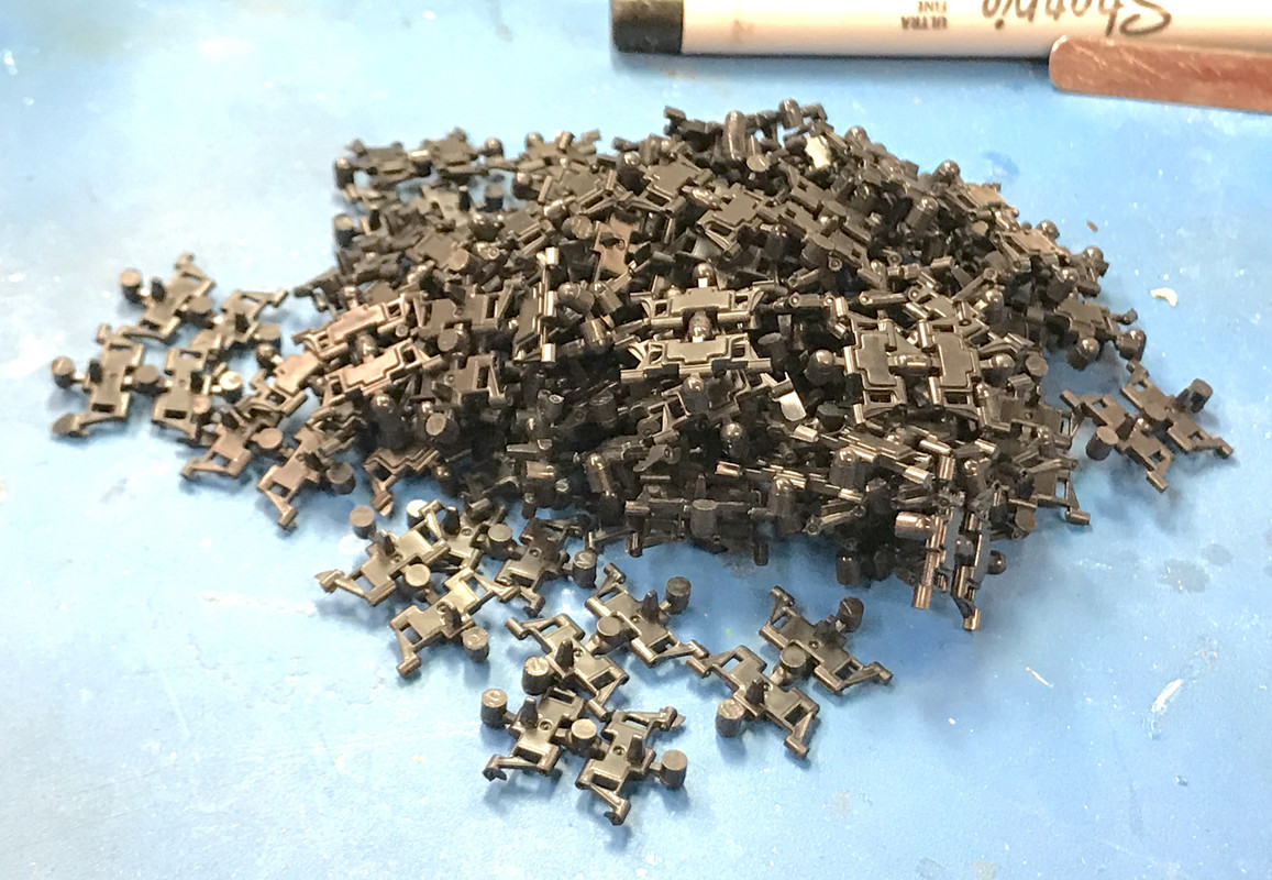
But before you can click them together, you have to clean them up. They molded in pairs. The outer ejection stubs were easy to clip off with flush cutters. The inner connectors were in a position that wasn't conducive to flush cutters. I didn't want to cut them with a #11 blade since a slip could damage the mating surfaces. I sharpened the end of an old #11 blade so I could plunge cut the connectors without getting near the hinges.
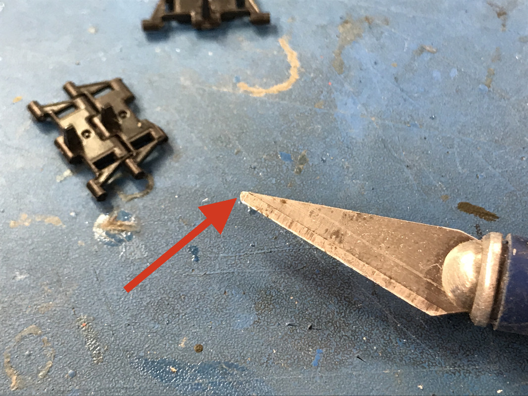
This tool worked pretty well, but there was also more flash on some percentage of the link sets. I used my regular #11 to remove these. 
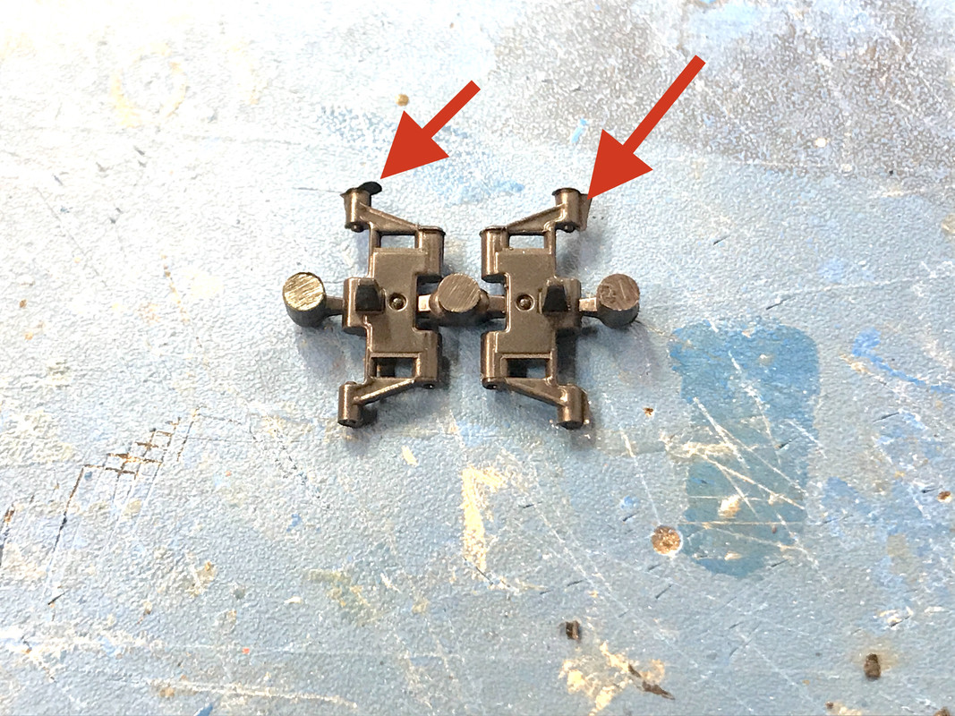
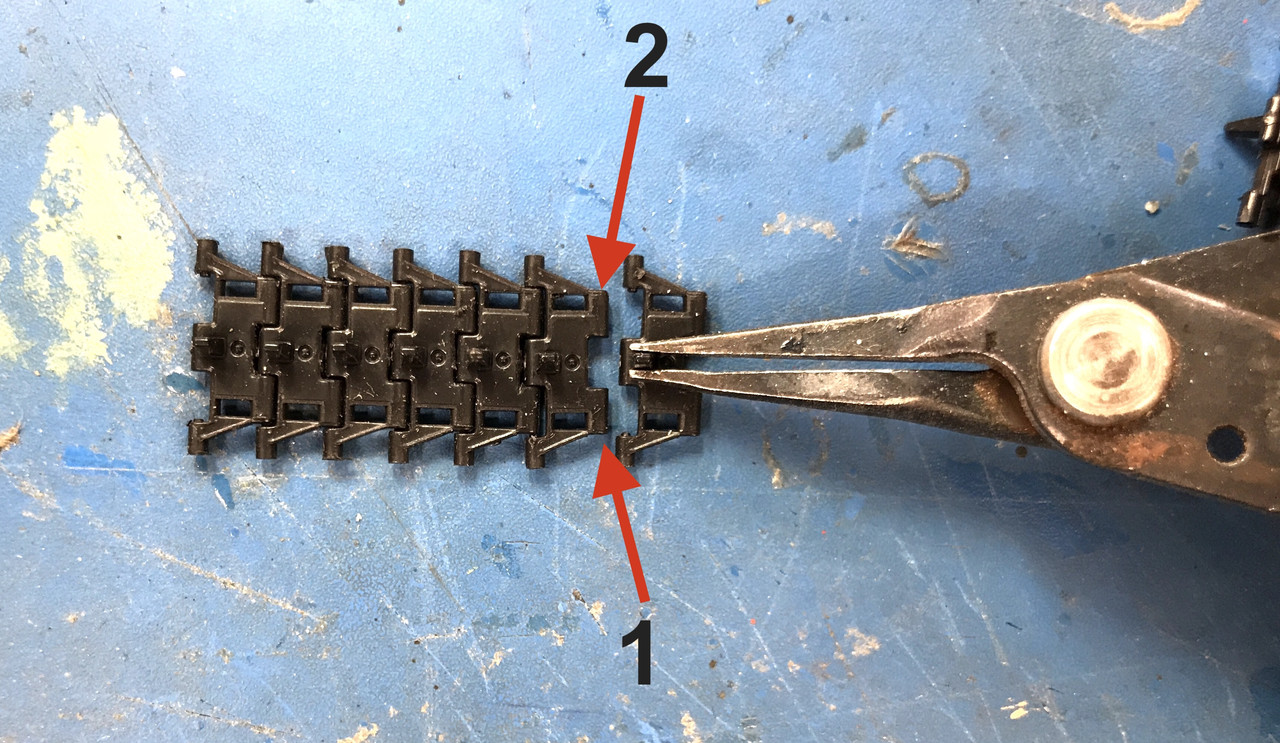
I found that it was easiest to put the links together by grabbing the guide lug and having it facing the mating link, tilting the link so the nub on the near side engages and then snapping in the second side. Some fit more snuggly than others. In fact, some are so insecure that the tread will probably break if you try to "play" with this model even though they will articulate.
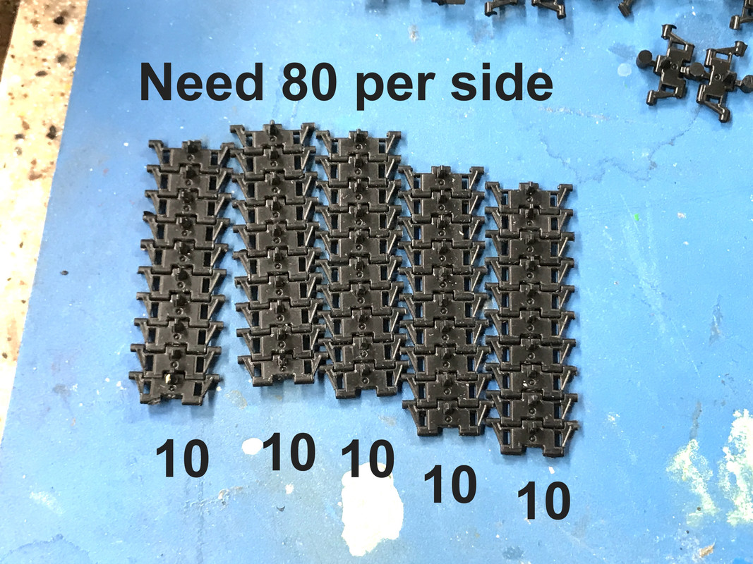
The model requires 80 links per side. I'm building them in sets of 10 which when I get 8 sets will be joined into a complete tread. Having them molded in twos makes it easy to pick 10 out of the big pile. The model has 8 extra pieces. One already got damaged. This was about one hour's production. I got faster as I went... learning curve.
As I'm getting familiar with the Bradley and with my intimate knowledge of the M113 APC, it's really obvious that, even though both were made by FMC, and both are essentially aluminum boxes, the Bradley (especially in the BUSK configuration) is so much more robust. You can actually survive in a Bradley. The APC was a different thing entirely. 2 inches of aluminum would stop a rifle bullet, but not anything made to hurt armor.

  • Member since
    December 2002
  • From: Valrico, FL
Posted by HeavyArty on Thursday, March 11, 2021 7:11 PM

More great work.  


One small issue.  You have the handle on the rear door on the exterior of the ramp upside down.  

Pointing up is the position to open the small door. 

Down is the closed position.

Gino P. Quintiliani - Field Artillery - The KING of BATTLE!!!

Check out my Gallery: https://app.photobucket.com/u/HeavyArty

"People sleep peaceably in their beds at night only because rough men stand ready to do violence on their behalf." -- George Orwell

  • Member since
    December 2002
  • From: Fort Knox
Posted by Rob Gronovius on Saturday, March 13, 2021 10:15 AM

Gino's right, with the bottom of the handle at the 6 o'clock position, there is a corresponding tab with a hole in it. That's where the series 200 padlock to secure the vehicle goes, whereas on your M113 FOV, the padlock is on the driver's hatch.

Anyway, the bottom end of the handle has a hole in it and the padlock goes through the hole and through the tab to lock the vehicle while it is parked in the motor pool.

  • Member since
    March 2012
  • From: Louisville, KY
Posted by Builder 2010 on Saturday, March 13, 2021 12:51 PM

That sure looks right! The instructions, I believe, show it in the upside down position. I can remove and adjust. I remember staring at that drawing trying to figure out how the handle sat.

I got one track complete yesterday,

but am totally dissatisfied with the strength of the snap joints. When simplly picking up the track—and not trying to put it on the tank—it fell aprart in at least three places. Some of the joints are pitifully weak. I resorted to drilling and pinning some of the links with a 0.022" carbide drill and same-sized phos-bronze wire. But this is horribly slow and I ruined a few pieces by not getting the drilling dead center.

Which led me to plan B... ordering Friulmodel Bradley metal track links. They're pre-drilled and have pins that pass through the entire link as in the prototype. You have to do some filing to remove flash, but I can live with that. At least the track will stay together and would be fully articulated. Cost around $30. I didn't buy any other aftermarket for the model, so I can handle that.

The above pics were taken with my new iPhone 12 Pro. My wife and I splurged the other day and finally got Apple Watches and new iPhones to go with them. Our daughter wanted us to have the watches since we're now at the age where falls can occur and the watch will sense this and alert the right people. We had iPhone 7s. I got the Pro because of the fabulous camera system, and she got the Mini. I bought the pro because between posting all my work and the magazine articles, I'm taking thousands of hi-res pics per year. I just took these yesterday just to test it out. I did not spend much time doing this, nor did I really test all the variables.

The night photo capability is breathtaking.

The wide-angle shot of the layout shows everything is beautiful focus. I don't have to use the Canon EOS and image-stacking software to get this.

And it can do one more thing... You can set up the camera and reproduce what you see on the iWatch. You can then snap the picture on the watch. This enables you to put the camera in unique places without having to physically operate it. Like this.

What's most impressive about the optics is the depth or field without any fussing around. Not only is the shed in good focus, but the entire mountain is as well. The camera was about 3 inches away from the shed, but the mountain was five feet away. No more image stacking software. There's apps avaiable where you can adjust the focus manually so I could use the iPhone with image stacking if that's ever necessary.

or this...

or even this...

The CPU's AI capabilities are extensive and it adjusts exposure in various parts of the image to balance it. That's how it handles the night photography. Apparently, it does not work in the telephoto mode. The camera switches seamlessly from ultra-wide, wide and telephoto lenses as you adjust the magnification. 

It was a hard-sell to convince my wife that the optics in the 12 pro are worth the extra $200. It also comes with 128GB memory standard, versus 64GB in the 12 standard. That's $100 of the $200 right there. With the photo work I do, I believe it is justified. It basically puts my Canon EOS into cold storage. I may just sell that along with the old phones. The color rendition on the phone is substantially better than the old Canon.

The above only scratches the surface. I didn't even mention that the LIDAR laser range finding, you can scan, measure and even export STL files for potential 3D printing. I need to do more research about this feature before fully understanding its role in my model work. Stay tuned.

  • Member since
    December 2002
  • From: Valrico, FL
Posted by HeavyArty on Saturday, March 13, 2021 1:09 PM

Interesting that you had issues with the tracks.  I love these tracks and have had no issues with them.  I have bought extras of them off eBay for my other Bradley and MLRS builds.  If you don't want them any longer, I'll take them off your hands, just PM me.


Gino P. Quintiliani - Field Artillery - The KING of BATTLE!!!

Check out my Gallery: https://app.photobucket.com/u/HeavyArty

"People sleep peaceably in their beds at night only because rough men stand ready to do violence on their behalf." -- George Orwell

  • Member since
    March 2012
  • From: Louisville, KY
Posted by Builder 2010 on Monday, March 15, 2021 9:17 PM

I stopped work on the tracks and my LHS ordered the Friulmodel Bradley tracks. I continued working on the hull until I was agin stopped because of the missing "Q" sprue. I built the airconditioning units, again, the "Q" sprue even impacted this assembly with the Tail Light house being a "Q" part.

The AC outer wrapper had a slight warp spreading the side walls with some tension. To ensure that the side pieces could glue without being a pain, I lightly clamped them just to straighten the walls and not stress it in the other direction.

After gluing it all together, I painted the molded-in fans flat black. I then primed the outside of the PE parts. These included round grills to cover the fans and a rectangular grill to cover the entire front. Since I wanted the black to add some depth inside, and couldn't airbrush the desert sand without painting over the black fans, I brush-painted the first set of grills after they were attached with thick CA. 

And then brush-painted the outer grills the same way. With this, I went as far as I could with the AC units.

I could go no futher on the hull so I started working on the turret. Again, nicely engineered.

There's quite a few things that go into the bottom half of the turret, including, Gun Breach*, Gunner's controls, radio, manual and power traverse and manual elevation, storage boxes and the co-axial 30 cal. machine gun. I wondered why the Bradley didn't have the Browning M2 heavy MG, but then I realized that when you have a 25mm Bushmaster, you don't need a "heavy machine gun", you've got the heaviest machine gun already. I was annoyed that the model didn't detail the breach mechanism. It doesn't seem that any Bradley models do it. Why is that? There's a polycap in the left trunion cap so the gun will hold what ever elevation position you set.

That little tray below the gunners controls and the LCD is going to be the keyboard. There's a keyboard decal that goes there. The joystick on the side controls the guns. Between the LCD, joystick and keyboard, it's more light fighting in a video game than a military weapon. I will have to put some masking over the already-painted LCD.

Here's a reverse view. All of this interior stuff starts out painted sea foam. I be picking out all the details with the other colors after base coating it.

Here's a detail shot of the traverse gear. There's a cute little PE protection cage that goes on. Don't know why it's there since no moving parts would be exposed. It could be a heat shield to protect the crew. That motor could get pretty hot.

Tomorrow I'll continue with the turret with the roof details. There's a ton of stuff there too, but unfortunately, you won't see much of it.

  • Member since
    December 2002
  • From: Valrico, FL
Posted by HeavyArty on Tuesday, March 16, 2021 8:00 AM

Still chugging along and looking great.

Builder 2010
I was annoyed that the model didn't detail the breach mechanism. It doesn't seem that any Bradley models do it. Why is that? 

Meng is the only company that does a turret interior in 1/35.  I don't know about any of the 1/72 ones, but I doubt they do either.  The cover is correct, but a breech would have been a nice option.  It isn't that hard to scratch though.  I did one on my M2 Reforger a couple years ago.

One thing Meng missed is the two feed chutes from the ammo box in the turret base up to the forward turret shelf to the left of the breech.  These are flex chutes and I used a couple pieces of left over Eduard ammo chutes (.50 cal I think) to replicate them.  You can see them in the below pic and what they look like in reality further below .

The open ends of the two chutes above attach to the two tabs sticking up on the top left of the ammo can (part M18) at the front of the turret base.

Another area Meng got wrong is the radio at the rear of the turret.  The one in the kit is an old Series 46 system.  These were replaced in the mid-'90s with SINCGARS (SINgle Channel Ground/Airborne Radio System).  They look totally different.  Many companies make SINCGARS so they are easy to replace.

SINCGARS ICOM

SINCGARS ASIP, newer version which the M2A3 usually carries.

I like to use 3D printed SINCGARS sets from an Armorama member at Shapeways.  They are really nice.  You can see it on my M2A2 backdate of the Meng M2A3.

At Shapeways: https://www.shapeways.com/product/8DXNXZRSW/1-35-1-16-1-25-sincgars-radio-set-msp35-025?optionId=62376402&li=shops

It includes two complete radios sets (1 ICOM, 1 ASIP), handmikes, speakers, a couple hand-held radios, and a PLGR GPS unit.

He also has a set for the intercom system that includes the intercom control box, J-boxes, and a few other pieces. 

https://www.shapeways.com/product/SHWKXSPNN/1-35-an-vic-3-v-intercom-basic-set-msp35-001?optionId=59672427&li=shops

I used the intercom set in mine as well, along with lots of wires to connect it all.

Gino P. Quintiliani - Field Artillery - The KING of BATTLE!!!

Check out my Gallery: https://app.photobucket.com/u/HeavyArty

"People sleep peaceably in their beds at night only because rough men stand ready to do violence on their behalf." -- George Orwell

  • Member since
    March 2012
  • From: Louisville, KY
Posted by Builder 2010 on Tuesday, March 16, 2021 6:52 PM

Leave it to Shapeways to have a solution. Since the radio is so difficult to visualize, I'm not going to sprint for the $12 + shipping needed to change it out. But, thanks Gino for more terrific information. 

I'm finding something out about myself. If there's an ambiguous part that's kind of hard to discern how it's supposed to being built and there's a 50/50 chance to get it backwards, I will get it backwards.

Case in point... The coax gun was not fitting correctly. The trunion shaft was sticking out too far pushing the machine gun at a funny angle and it wouldn't seat. And then there was this...

There was a cross-bar in the hole that seemed to be wanting a shaft with a slot. But the shaft didn't have a slot. Well... you guessed it. I had installed the gun upside down. More troublesome than that, I had solidly glued the trunion brackets, and there were armor plates on the top and bottom of the gun that had to come off. I was able to work the upper one loose which had that tiny PE part on it. It flew over my "Parts Barrier" and was on the floor behind the work area. I found it and the PE was still attached (although it came loose three more times and is now waiting until the turret is finished before I attempt to attach it one last time.

I was able to re-glue this plate in the proper location. 

You can see in this image the reversed gun showing the shaft with the split to accept the coax. You can also see some of the knife damage that needed fix'n too.

The lower plate got destroyed in the removal and I had to scratchbuild another. I also munged up the gun a bit in the process of wrecking all these cured glue joints and had to do some refinishing. 

I got the gun back together and installed the coax properly. When installed correctly, the keyed attachment keeps the coax in sync with the main gun. The gun, when repainted will look pretty decent.

And then there's my wonderful parts catcher. I caught a lot of parts today, includin this microscopic travel lock that goes on the gun mantlet. It fell there at least two times. I also caught a bunch of other stuff. Only one part got past it by slipping down the gap between the catcher and my shirt. I tie the catcher to my shirt with an old-fashioned, low tech clothes pin. BTW: the photo is an enlargement. The cloth is some surgical drape given to me by my orthopedic son in law.

I really thought I was building that gun correctly and studied the drawing for a while and still got it backwards. I spent almost the entire time in the shop today fixing this screwup. You have those days sometimes.

  • Member since
    January 2016
Posted by suomi39 on Wednesday, March 17, 2021 9:15 AM

I've had my share of days like that too, Builder. You've done well pushing through, and I'm sure once it's all buttoned up and painted you'll almost forget it happened.

I often need a break after something like that, both to let off the frustration (this is supposed to be fun...) and also for my subconscious to come up with a solution, if there's one to be had other than throwing the whole thing away. Ha!

Good work on the PE catcher too. Sounds like a big time and knee-saver. 

This build is looking great. Your attention to detail and patience realy shows. Particularly here inside the turret. And yes, the photos are looking great -- gonna have to look at the 12 Pro when it's time to upgrade myself -- but I want to see more photos of that room! You have a gallery somwhere?

  • Member since
    March 2012
  • From: Louisville, KY
Posted by Builder 2010 on Thursday, March 18, 2021 6:28 PM

Thanks... I try to do my best.

Started to write yesterday's post last night, but got diverted and then it timed out. So this post includes yesterday's and today's short 1 hour session.

The fix worked perfectly and after it dried overnight all was secure. None of the repairs are visible. I finished detailing the lower and upper portions of the turret. I remembered to add the decals as I went, but realize today that I forgot to install the totally-unviewable overhead light units. There is simply no way to view them and so their loss will not be missed by anyone.

After putting all little bits and pieces into the model I airbrushed both halves sea foam. When dry I overcoated all the parts that were to be painted other colors with Dullcoat to prevent the Tamiya paint from melting the sea foam into the top coat. Tamiya paint doesn't cure by cross-linking. It can be redissolved over and over using IPA based paints.

After picking out all the details and guessing about some, I put the various decals in place.

There's more details you can add inside this busy place, but frankly, with no way to view, I didn't do it. Suffice it to say, that the M2A3 Bradley looks like driving a computer rather than a war machine. It even has a "joystick". The commander has a keyboard and screen so you better be comfortable with digital stuff to feel at home in one.

It was time to work on the turret basket. There is grillwork that fills a gap in the two solid side pieces. Meng includes a formed piece of styrene upon which you deform the PE grill so it will fit the odd contours of the turret basket's opening. I did the first one improperly by pressing it onto the convex side of the form. I kinked a tad. For the second piece I realized that you form the brass into the concave side which actully has an indentation to accept the brass. The picture shows the proper way to bend the brass.

I inserted the brass into the basket openings and used some strategic drops of thin CA to affix the PE. The commander and gunner's seat are glued in at this time. Doesn't look like a very comfortable place to sit for a long cross-desert drive...

The basket is glued into a coupling ring which then mates with the lower turret. The basket halves were a little springy and needed clamping to hold them firmly to the inside mating surface of the ring before the glue set. There's only one way to glue this on.

After assembly this too was airbrused sea foam and then the details picked out anddecals applied. 

I put some grime on the turret floor. More sophisticated weathering could be done, but you will not see it. The only way that viewing this depth of the turret would be to light the interior with fiber optic LEDs. I could do that, but am not. The basket parts all go together and then the lower turret is glued to this assembly.

There was one piece of styrene that needed to be installed before joining the turret halves. I was a tricky piece (for me) to get the orientation correct. I really only went on one way, but it took a lot of fiddling to find that "one way".

Turret was joined.

That finished up yesterday's session. Today, with only one hour, I was still able to get more parts on the the ever-increasingly-complex turret. I got the additional front armor in place, and some more armor on the right turret side.

The smoke launchers consist of five parts: Base and 4 separate tubes. I was very careful to cut the tubes of the sprue so they wouldn't take off. I had four sitting on the work surface. I glued on three of them on the first unit and the fourth was no longer where I put it. The model has three varieties of these tubes: covered, open and elongated. I was going to add an open one to replace the lost one and did so. Then I saw a piece of plastic tubing stuck in the notch between my woodworker's vice and the table. I used a tweezers to pull out this piece of scrap, and then I saw the missing smoke ejector tube sitting in the notch next to the scrap. How the heck it got there, I have absolutely no idea.

Notice how the additional armor plating completely seals the gun trunions. The gun still rotates nicely. There's a flexible piece that closes that top opening. On all of this added plating goes the explosive reactive armor blocks (ERA). I imagine the Bradley is a pretty survivable vehicle. Anyone have any data to this end? Gino?

Here's the armor on the left side. The Meng parts fit perfectly. This view show how little you can see of the interior.

  • Member since
    December 2002
  • From: Valrico, FL
Posted by HeavyArty on Thursday, March 18, 2021 8:50 PM

More great work.  It is coming along great.

Builder 2010
The model has three varieties of these tubes: covered, open and elongated.

There are three types of tubes, sort of.  The "elongated" ones are with smoke grenades installed.  There is a line around it near the business end.  This is where the smoke grenade and tube meet.  The outer part is the smoke grenade and will be either seafoam green (M76 - IR smoke) or black (M90 - visible smoke).

Builder 2010
I imagine the Bradley is a pretty survivable vehicle. Anyone have any data to this end? Gino?

Yes and no.  With all the ERA and extra armor, it has proven to be very survivable against kinetic rounds (HEAT, HESH, RPG, small arms, Heavy MGs, etc.).  However, with a big, flat bottom, it is suceptible to mines and burried IEDs.  The A3 version counters this some with the individual rear seats and harnesses in the back, along with reinforcing the floor.  It is an improvement, but still not the best against explosions from underneath.

Gino P. Quintiliani - Field Artillery - The KING of BATTLE!!!

Check out my Gallery: https://app.photobucket.com/u/HeavyArty

"People sleep peaceably in their beds at night only because rough men stand ready to do violence on their behalf." -- George Orwell

  • Member since
    March 2012
  • From: Louisville, KY
Posted by Builder 2010 on Friday, March 19, 2021 6:44 PM

Thanks Gino! So that's what they look like. I'm doing them all with the covers in place.

Today was more turret work, starting with the top armor, hatches and hinges. Almost all of the armor plated needed some cleanup, and some, like this one needed some serious cleanup. I mostly use my MicroMark Plastics Chisel and then a sanding block. If you don't get the ejection marks flush the armor will not sit flat on the surface.

Both the gunner's and commander's hatches were two-part affairs with an inner liner and outer shell. Then, in the case of the commander's hatch, you added the seondary hinge mechanism which has the hinge shaft to the turret. The secondary hinge should have been able to articulate since it would make seating the hatch more positive. Instead you glue it in at the bottom position. I should have drilled and pinned it.... too late.

The gunner's hinge had one end blind with a hole for the hinge pin on the outboard side. The inboard was one of those snap-fit kind. Then there's a blind hinge that goes on the inner-most position that's a dummy. The commander's hinges are both snap types and are glued in BEFORE the top-rear armor plate is installed. The Gunner's hinges go in after this piece is in place.

Here's the gunner's hinge in detail. BTW: Both hatches open and close nicely.

The blind hinge on the commander's hatch goes into the gap between the actual hinge and turret proper. You must make sure to have the actual hinge glued in pushed completely to the left so the dummy hinge will drop in properly. When I was assembling this, I didn't understand why there was some much space in the recess. When I went to put in the dummy hinge, it became crystal clear why there is a gap.

There was another very small-delicate detail that went in behind the gunner's hatch. It was a tricky little bit to get the lever aligned properly. It took a lot of trial fitting to get right before gluing. I'm going to stop now so I don't lose this. I'll edit it later.

  • Member since
    June 2018
  • From: Ohio (USA)
Posted by DRUMS01 on Friday, March 19, 2021 7:11 PM

Builder2010, this is looking fantastic! I appreciate you sharing the ups and downs of your build. It feels almost like I;'m building the kit with you when reading your string.

Keep up the grat work and thanks for sharing it with us...

DRUMS01

"Everyones the normal until you get to know them" (Unknown)

LAST COMPLETED:

1/35 Churchill Mk IV AVRE with bridge - DONE

NEXT PROJECT:

1/35 CH-54A Tarhe Helicopter


  • Member since
    March 2012
  • From: Louisville, KY
Posted by Builder 2010 on Saturday, March 20, 2021 4:00 PM

Since you like it so much I'll finish my interrupted post from yesterday.

After getting the hatches in place, I started working my way around the turret in a counter-clockwise direction putting in the rest of the armor and some little finicky doodads.

One of these is a lever assembly that goes behind the gunner's hatch. I'm sure Gino will tell what it actualy does, but it looks like some kind of latch that holds the hatch in the open position. The hinge part of this little bit fits into two slots behind the hatch. Then you have to apply the lever. The instructions show attaching the lever BEFORE the lower part is on the tank, but there's no way to hold this little piece still while you get the lever in its proper location. So I glued the lever AFTER attaching its base.

It really took a lot of fussing and pre-fitting to get the lever to rest at the proper angle that clears the hatch and lets the hatch actually open. It would a pity to spend so much time and care NOT getting glue on the hinges only to have it blocked by some ill-defined detail.

The armor apliqué panels all have PE ERA support brackets and then the two-part ERA blocks themselves. I really hate gluing PE to styrene. I was using my usual gel CA since it stays put when applied, cures a bit slower so you can reposition it, but it's no more adhesive to polished brass PE than normal CA. The first piece had five of these A-frame brackets. They are supposed to sit down onto three pins protruding from the plastic. The pins are just a teeny-tiny bit too large (or the PE holes just a tad too small) to let the brass drop easily down over them. You have push them pretty-hard to get them to seat. Meanwhile, the CA is curing. This first assembly was challenging but worked out okay. I should have drilled all those PE holes a bit bigger, but I got lazy and really paid for it.

The single block part next to it went together okay too.

Notice how a tiny bit of the PE shows above the blocks letting you know there's a reason to spend so much time gluing the blocks to these PE frames and not directly onto the styrene.

The next block, the front right one, was a bit of a horror. I got the parts all assembled and then one of the A-frames broke loose. The only way to fix it was disassemble it and start over. If you're like me, once you don't get CA to work right the first time, it doesn't get better with age. Each successive try makes it worse. The CA built up on the styrene further obscuring those pins. And I already mentioned that the Gorilla Gel CA had no trouble sticking like crazy to the styrene and did not remove easily. I got this one together with lots of perserverence.

The one on the opposite corner was even worse. It got so bad that I had to simply remove those stubs so the PE would sit directly on the styrene. I first drilled the stubs with a 0.032" to locate them when I scraped them off. I needed to be able to reset the PE to the same location when they were gone. That got the PE glued! 

Then I had to glue on the EPA block. The EPA blocks also have a triangular locating lug (or lugs depending on block size) that fits inside the hole of the same shape in the A-Frames. It's designed to act as a guide to help you glue the EPA onto the PE in the correct orientation. This too wasn't working since the CA was building up around the lug from my multiple and aborted tries. So I scraped that lug off too and simply positioned it by eye to show the same amount of CA protruding from the top. 

This was one of those not-so-much-model-building-fun times.

The last bit of ERA was the single block that flanked the gun's left side. This too, while only having one piece of CA below, was a pain in the butt because when I first got it together, it blocked the gun from elevating and had to be moved to the left. That meant ripping it off, cleaning up more cured CA and so on. Not fun. But alls well that ends well and they're all on and when painted they will be okay. They're very delicate and a bump could knock them off their backing plate. Remember: These scale models are not toys!

The last thing I did yesterday was put on the flexible piece of simulated canvas that keeps dirt out of the gun mantlet area. I was holding the turret in the Panavise to add all these parts since you MUST KEEP the turret stationary while working on it.

The armor apliqués had some ejection pin bumps underneath like these that needed removal to keep them nice and flush with the rest of the turret. This was the worse.

So this brings y'all up to date. See ya on Monday. Don't know about where you live, but the weather here in Louisville this weekend is lovely. I'm barbequing a nice steak for our dinner tonight.

  • Member since
    October 2007
  • From: Louisville, KY
Posted by pordoi on Saturday, March 20, 2021 5:08 PM

It has been very interesting and entertaining following along with your detailed description of this project and reading the input of others who have had first hand experience with this vehicle.  For me, it really provides some understanding of the engineering that went into their design.  Looking forward to seeing this project to its completion.

As an aside from a fellow Louisvillian, we are looking forward to rack of lamb on the grill this weekend.

  • Member since
    March 2012
  • From: Louisville, KY
Posted by Builder 2010 on Sunday, March 21, 2021 10:36 AM

Tonight will even be a better night to cook out than last night, and last night was great. The steak came out great and between that and the ice cream I had for desert, I gained a pound and half.

  • Member since
    October 2007
  • From: Louisville, KY
Posted by pordoi on Sunday, March 21, 2021 6:51 PM

Builder 2010

 The steak came out great and between that and the ice cream I had for desert, I gained a pound and half.


Nothing that a full day at the bench won't cure. Wink
 
 
  • Member since
    March 2012
  • From: Louisville, KY
Posted by Builder 2010 on Monday, March 22, 2021 9:48 AM

True... they say the brain uses the most calories in the human body. I'm thinking all the time when working on the bench. "How the hell did I just do that and how can I fix it?!!" or other thoughts like that.

  • Member since
    March 2012
  • From: Louisville, KY
Posted by Builder 2010 on Monday, March 22, 2021 5:53 PM

Happy Spring and Happy Monday. Weather here today was delightful, but I only got glimpses of it since I was down in the basement building a Bradley.

Work continued on the stuff added onto the turret. One of the things I couldn't work on was the bullet proof glass enclosure of the commander's hatch because the frame was a "Q" part. I did, however, built the Commander's IR optics and the gunner's special visual system. The IR system is fully articulated. 

The first part was the front face of the gunner's vision system that has a PE screen, 2 doors and some small hinge parts that would extend into the turret (on the real thing) to actuate the doors. One of these tiny plastic hinges disappeared so I made two of them out of 0.022" wire. I was able to drill the very small hinge to accept the wire.

There is a transparent piece that goes inside. I painted its framing with desert yellow, but alas, this is all mostly invisible, hidden behind the PE screen.

Regardless, I was careful gluing it in SO if you actually could see it, it would look great.

The IR system was more complex with a left end of several parts, a multipart base and a right bracket. This then sits on a base that has another polycap that lets it rotate.

The only problem I had was I kept bumping that small hand grab. I finally got it straight and it will dry overnight. This part also has a transparent part and WILL be seen. I will have to mask it when painting the exterior.

The IR fastens to the turrets flank whereas the gunner's visual system secures to the turret top.

Then I lost one of these.

It looks like a small HF antenna. I ended up spending 15 minutes looking for the darn thing. I heard it hit, what I thought, was my work area to the rear of the bench. I have those cardboard barriers which do stop things from leaving the area. I couldn't find it so I ended up making my own out of wire and Bondic UV Curing resin. I tapered the antenna using the Dremel with a diamond grinding burr.

I was searching the instructions to find out where the last piece of PE was going to go and found that I missed putting on one of the lifting eyes. This was another one that you first glued underneath the armor plate and then attached the armor to the turret. The eye has a flange that sits into a boss on the armor's underside. I was able to get the eye in place from the front by carefully shaving it down so it would drop into the slot into the armor and glued it tight. You really can't tell by looking at it that I attached it out of the correct order.

As I mentioned, I was stymied by the missing "Q" parts to make the commander's bullet proof shields that surround the front of the his hatch. I was able to do the rest of the installation. One of these was part of a linkage that attaches to the gun and another part that glues to a hinge on the turret roof. There's another part of the linkage that goes in later which means that this part is just hanging there ready to be broken.

  I was able to glue the IR and Gunner's optics onto the turret. I checked to see if I'd be blocking putting on the commander's shield later and it looks like I won't have any problems. 

Here's a frontal view showing the cool stuff that clogs this turret.

Here's a top view.

I have some more stuff to put together before I hit the missing-"Q" sprue-wall. Including in this is the TOW missile apparatus, the bustle and its attendent parts including prominent anttena. When that's done I hope my tracks will arrive at the hobby shop and/or the "Q" parts arrive, or I will have to find something else to do. I could paint the turret without the commander's shield since that will have a lot of transparent parts and may best be installed after the bulk of the painting is done. But the entire skirt assembly with all of that ERA is extensively "Q" parts.

  • Member since
    March 2012
  • From: Louisville, KY
Posted by Builder 2010 on Tuesday, March 23, 2021 5:58 PM

Even though today was an exercise day, I got started early enough that I had a normal work session too. I continued work on the turret appliances starting with the TOW launcher. It's a nice little bit of assembly work except for the tiny link that keeps it in the open-for-business position. I reinforced this link from behind with some Bondic UV curing resin. 

The inside tubes are supposed to be O.D. so I painted it first, built the housing, and then later masked the openings so I can airbrush the entire turret. The TOW launcher articulates up and down, but you can't move it from stored-to-deployed position due to that immovable small link. This is the loading end.

And here is the business end showing the very fragile link that would keep the cover moving on top of the launcher.

With the TOW in place, the bustle was next. The bustle, unlike the tubing variety that graces many tanks, is a pretty solid affair. On it goes four more antennas, including those small HF ones and two large I-don't-know-what-they-do variety.

Here's the bustle before attachment.

Gino, so just what are those large antenna for?

The bustle glues to the turret just by the bottom edge and it's not as robust as I would like.

And a rear view...

And lastly I finished that linkage on the gun which turns out to be a mechanical gun sight that would track with the guns bore as it elevates. The linkage is fragile. Even more fragile is the small plastic rear sight and the PE front site. I drilled a hole in the front sight so you could see through it. And now I'm going to find out that it really doesn't have a hole...

Another view...

And lastly, I put that barrel latch PE that came off a few times earlier. I dropped it three times, but found it all three including twice into the parts catcher. It's a bit more protected now with the plastic canvas part sitting above it. Regardless, I have to be very, very careful of how I pick up and hold the turret since almost everything on it is breakable. 

I masked the turret basket in prep for painting tomorrow. I also used Microscale Liquid Mask to mask the periscope faces and the transparent window in the I.R. unit.

That is one busy piece of modeling. I know the vehicle itself is pretty well protected from a lot of munitions, but what about all that hardware hanging on the roof? Seems like you could blind a Bradley fairly easily, but I may be wrong.

I can paint the turret tomorrow, but can't do the hull because of all the missing armor and ERA parts. And then I will be out of work on this model until the "Q" parts arrive and my LHS gets the Friulmodel tracks. I have a 1/35 Kitty Hawk Sea Hawk heli on layaway at the hobby shop. If I have to wait too long for the parts, I will pick that up and maybe start construction. I also have some more significant model RR work to do. I'll find something.

  • Member since
    December 2002
  • From: Valrico, FL
Posted by HeavyArty on Tuesday, March 23, 2021 7:18 PM

Still coming along well.

Builder 2010
On it goes four more antennas, including those small HF ones and two large I-don't-know-what-they-do variety.  Gino, so just what are those large antenna for?

They are IED jammer antennas.  They put out a signal that jams radio-activated IEDs. 

The other two are not HF antennas either.  The one on the left side is for EPLRS (Enhanced Position Locating Radio System), sort of like a tracking system used by delivery trucks use.  It feeds data to the screens inside the turret and crew compartment that shows where friendly vehicles are on a moving map.  Users can also input weighpoints and enemy locations as well to keep everyone updated.  The small antenna in the middle of the bustle rack is a digital antenna for digital commo.

Builder 2010
The bustle glues to the turret just by the bottom edge and it's not as robust as I would like.

Actually, the left side triangular piece (H7) should angle in and attach to the turret side.  

Builder 2010
And lastly I finished that linkage on the gun which turns out to be a mechanical gun sight t... I drilled a hole in the front sight so you could see through it. And now I'm going to find out that it really doesn't have a hole...

Well...Actually you are good.  It is a peep sight with a hole through it.

Gino P. Quintiliani - Field Artillery - The KING of BATTLE!!!

Check out my Gallery: https://app.photobucket.com/u/HeavyArty

"People sleep peaceably in their beds at night only because rough men stand ready to do violence on their behalf." -- George Orwell

  • Member since
    March 2012
  • From: Louisville, KY
Posted by Builder 2010 on Wednesday, March 24, 2021 6:16 PM

Gino, I knew you'd be able to fill in my knowledge gaps. Thank you.

Painted the turret. I first shot it with straight Tamiya Desert Yellow. I then mixed a batch of the same with a reasonable amount of Tamiya Buff. I used to on all surfaces except the bottom. I then, using my Badger 200, top-feed fine line gun, I added more white to the mix and shot just the upper surfaces for more fading.

BTW: The box art clearly shows that the mechanism on the gun base is a hollow gun site. It's a shame they didn't Photo-etch the part like that.

I will have to repaint the coax gun since I didn't mask it. Need also to check the color of the rotating shield behind said gun.

The color transition is subtle which is what I wanted. There were no broad flat surfaces on this assembly to warrent just lightening the center of the panels. Here's an underside look. You really can't see the darker color, but it's there.

I then over-coated the whole deal with a new product (for me), Humbrol Matte Varnish to seal the Tamiya paint so I can use washes or whatever as I add some more character to the surface. It dried beautifully, but it's water-based so I'm not sure how it will behave when I do anything else to the surface. Anyone have experience with this product? We'll see how it goes. Actually, I should have gloss-coated it since it works better with panel-line accenting and adding any decals.

With that drying I decided to do the road wheels. Instead of painting the tires and then using the Meng photo-etched mask to paint the hubs, I used the PE mask to cut out circles of Tamiya tape to mask the wheel center. I painted the centers the Desert Yellow. For me it's easier to mask all the hubs and airbrush the tires, then to try and hold that mask to spray wheels after the tires are painted.

Here was the start of the circle cutting activity.

I found it easier to lift up the cut circle with a #11 blade and then use the tweezers to lift and place the mask, rather than using the tweezers for the whole deal.

After masking both sides, I poked a hole in the hub and used toothpicks to hold the wheels on some florist foam prior to painting. I needed to clip the toothpick's end a bit so it wouldn't bottom out before its taper snugged it into the hole.

And one more thing... I reuse my paint bottles whenever I can. I first clean them with alcohol, then MEK and finally 15 minutes in the ultrasonic cleaner. I bought the cleaner just to clean 3D print parts, but it's very handy for other things like this or deep cleaning my airbrush parts. The bottles come out spotless.

  • Member since
    March 2012
  • From: Louisville, KY
Posted by Builder 2010 on Thursday, March 25, 2021 5:52 PM

Well folks, I'm pretty much at the end until the tracks and "Q" parts arrive. I have a few decals to apply, but that will be it.

Today, I successully drilled .010" holes down inside the plastic antenna bases and added some 0.095" guitar strint (Light guage E), and made the whip antennas. I did not attempt to do the same for the one that I made out of phos-bronze. I felt that attempt to remove that part to remake it was not going to go well especially since there's a plastic cage around it that would inhibit access.

My first attempt at drilling these remarkedly small holes ended up breaking one of the carbide drills. These drills are so small and so hard that the slightest side pressure breaks them. I was using the pointy ends of a dividers to mark the approximate center of the antenna base. I first tried to go at it with the tiny drill and broke one. I then used a drill twice as large 0.022" to start the hole and give the tiny drill something to sit into. THis worked! I drilled the two antenna bases successfully and added the guitar string... not before poking my finger on the very thin, very hard steel.

I hand painted all the antenna details flat black.

I also selectively added some brown Tamiya Panel Accent color to the bolt heads, the textured part of the ERA and other various details. I'm not going to weather it any more than this. I don't like to heavily weather my models. High E guitar strings are just about the right guage for these antennas.

The turret is effectively done except for some decals. I'll apply them tomorrow.

The last thing I could do was finish painting the road wheels. I airbrushed them Tamiya Rubber Black, 

I then pulled the masking when the color was set enough to handle. 

If you look closely you can see some touchup is needed both in the desert yellow areas or the tires. I used the PE metal mask to do the touch up of the yellow, but still had to go back several time with alternating rubber black and yellow to get it like I wanted it.

I also made a black dot in the center of the hub which I believe is a sight glass for lubricant. And I used the Tamiya Brown Panel Accent to fill up the rim area and the bolt circle. I think the wheels are done, at least for now.

The wheels work!  

I hope that the 200,000 ton container ship that's blocking the Suez Canal is not holding up my "Q" sprue. What a mess! They've enlisted SMIT from the Netherlands which specializes in freeing up grounded vessels. They've also brought in a Japanese salvage company to help out. They will first pull out the ballast water, then the fuel and if that doesn't lighten it enough, they're going to have to start pulling off containers and there's literally a "Boat Load" of them. That will have to done with helicopeters. Either way, it's going to take a lot of time and the ships are backing up.

JOIN OUR COMMUNITY!

Our community is FREE to join. To participate you must either login or register for an account.

SEARCH FORUMS
FREE NEWSLETTER
By signing up you may also receive reader surveys and occasional special offers. We do not sell, rent or trade our email lists. View our Privacy Policy.