SEARCH FINESCALE.COM

Enter keywords or a search phrase below:

SBD Dauntless

73319 views
196 replies
1 rating 2 rating 3 rating 4 rating 5 rating
  • Member since
    June 2014
SBD Dauntless
Posted by Witold Jaworski on Sunday, May 10, 2015 3:45 AM

To build the model from scratch you need a good reference. Initially I decided to use for this purpose detailed scale plans from the monograph published by KAGERO in 2007 (Authors: Krzysztof Janowicz, Andre Zbiegniewski, ISBN: 978-83-60445-25-9). It contains SBD Dauntless plans in scale 1:48, traced by Krzysztof Lukasik.They are quite detailed (up to the rivets on the aircraft skin).

Apparently these drawings were made using Corel Draw or similar software. I scanned these drawings to do the basic verification. During this phase I did not find any flaws:

All the key locations of the fuselage are in the same place in the side view and the top view. The proportions of the length and the span of the top view is correct: 0.787. (This ratio comes from 996/1266. According the dimensions specified in this monograph, the length of the SBD-3 fuselage was 996 cm [32’ 8”], while the wing span of all the Dauntless versions was 1266 cm [41’ 6”]).

According the monograph data, SBD-5 fuselage was 4 inches (about 10.1 cm) longer than SBD-3. (The SBD-5 and SBD-6 fuselage was 33’ long. Most probably it has slightly different engine cowling and the propeller. The airframe after the firewall was the same in all Dauntless versions). However, in this monograph they have the same length!

Maybe the textual data contains an error? In such a situation I try to find an “official”, archival drawing of the aircraft. They do not show many details, but contain the key dimensions. I have found on the Internet a BuAer Navy drawing of the SBD-5, from 1944:

From the front view you can read the precise wing span: 41’ and 6 5/16“. From the side view you can read the exact length: 33’ and 1/8“.

This BuAer drawing isn’t an ideal source: it does not contain such details as panel seams. You can also find here some manual errors, made by its draftsman. While the aspect ratio of the top view matches the span and length specified in the dimensions, the actual fuselage length on the side view is somewhat shorter. (The positions of the wing and horizontal tailplane match in the side and top view match each other. It seems that the part of the vertical tail contour was shifted). On the other hand, the BuAer top view is a little bit asymmetric, and the firewall line is moved forward a little.

The good news is that the wing and the tailplane arrangement on the KAGERO plans and the BuAer drawing match each other:

Then I compared the side views of these drawings (I marked the correct fuselage length measured on the BuAer top view in red):

The differences of the side views are overwhelming: this is not only the engine cowling but also the cockpit canopy, the fin, and the tailwheel. (In general: none of these drawings shows the correct tail).

Thus, answering the title of this post, I can conclude: never trust the scale plans! I need a better reference, to fix these drawings.

In the next post I will show how to verify these drawings using photos.

Note: to work with these images I use two free, Open Source programs: GIMP (it is similar to Adobe Photoshop) and Inkscape (it is similar to Corel Draw or Adobe Illustrator). You can find more about them in this e-book.

  • Member since
    June 2014
Posted by Witold Jaworski on Sunday, May 17, 2015 2:35 AM

Before I start a new model, I collect its photos — as many as I can find, everywhere: in the books, magazines, on the Internet. Some of these photos are high-quality, detailed photos of restored airplanes. One of them is this a high-resolution photo from the web page of Chino Planes of Fame Air Museum:

Figure 2 1 A semi-orthographic photo of restored SBD-5 (from The Planes of Fame Air Museum in Chino)

This is a special photo: it was made from a long distance using a “telescope” lens, which minimized the perspective barrel distortion. The airplane on this picture lowered its right wing, so its bottom parts are slightly shifted downward, but except this area it is a perfect reference!

I placed this photo in Inkscape (a free, Open Source image editor), and set it horizontally (along the canopy frames). Then I mirrored it, for the comparison with the left side view:

In Dauntless there are two long parallel lines that were perpendicular to the fuselage centerline: the trailing edge of the wing center section, and elevator leading edge. On this photo they are also parallel (more or less). This is the proof that we can neglect the perspective (barrel) distortion.
Now let’s compare the BuAer drawing (see the post above) with the reference photo:

In the first post I mentioned that this BuAer side view is too short. To make a fair comparison, I marked on this drawing the proper fuselage length (as on the BuAer top view). As you can see, the drawing matches the reference photo quite well!

It fits the photo even better when you correct the tail contour (so it matches the fuselage length in the BuAer top view):

It seems that the BuAer drawing from 1944 matches the contour of the real aircraft quite well. In fact, it is much better than the contours of the detailed KAGERO drawings from 2007 (see previous post), which most probably are based on the drawings made by previous authors:

I think that these KAGERO plans “accumulated” many decades of various errors. Do not be surprised: before the 1990 it was practically impossible to make such a “photo verification” like this one. Even today authors are used to redrawing earlier plans. They seldom compare their work with the real photos in the manner shown above.

Concluding: there is no good reference among the existing Dauntless drawings: the BuAer lacks details, while the KAGERO plans contain too many deviations. The plans from other authors have similar errors (I will not elaborate about it here).

It seems that I have to crate my own drawings!

In the next post I will refer the progress of this work (I hope that I will show you the corrected side view).

  • Member since
    June 2014
Posted by Witold Jaworski on Saturday, May 23, 2015 2:39 PM

As I wrote a week ago, I am working on a better drawing of the SBD-5. It is based on more than 1000 various photos. Below you can see the first version of the side view:

 (click here to see the high-resolution version)

This is not an ultimate drawing: I suppose that it will be updated during my work, following the new findings about the airframe shape and/or details. The dotted lines mark the rivet seams, but size and spacing of these dots does not match the real rivets. I prepare these plans to build a model: that’s why I removed the outer wing section and horizontal tailplane. For these parts the most important drawing is the top view. To build them, on the side view I need the precise contours of their key sections (i.e. their airfoils as well as the incidence angles and spar locations). I draw three profiles: first of the wing root, then the root of the outer wing section, and then the wing tip. Two different sources specifies different wing tip profiles: NACA-2409 (Performance Test Report, 1942) or NACA-2407 (BuAer drawing, 1944). However, the bottom contour of the NACA-2407 seems to be a little concave. Because I did not observe such an effect on the photos, I decided to use the thicker airfoil of NACA-2409. I still have to verify this detail when I build the wing. The airfoils of the tailplane were specified nowhere. I copied its root airfoil from a photo.

While drawing the side view you still have to think “in 3D”. That’s why you can see around this silhouette some auxiliary sketches: the front view of the engine cowling, and the contours of the center wing section. I draw the latter element just to mark the exact position of the first rib of the wing. It was hidden inside the fuselage. Note that this airfoil was a specific modification of the NACA-2415 shape: the part of the wing that houses the main landing gear was reshaped. In the effect, the leading edge of the center wing section has a small downward inclination.

On the next week I will present side views of two earlier Dauntless versions: the SBD-2 and SBD-3. I will discuss where are the differences in the length of the SBD-5 and SBD-3, 4, as well as the mystery of the “missing 7 inches” of the SBD-2.

Within two weeks I will present the corrected/verified top view.

  • Member since
    June 2014
Posted by Witold Jaworski on Saturday, May 30, 2015 1:05 PM

In this post I will show you how do I create Dauntless side views. First I used the “semi-orthogonal” photo of the SBD-5 as the reference to draw the side view of this version. This is the most important picture, because it provides reliable “general reference”:

Then I used many other photos and sketched fragments of the other views to complete the side view details (note the multiple guide lines on these pictures):

Note the large B/W photo that I used to verify the shape of the propeller hub and engine cowling. I could not compare it with other areas — the cockpit canopy, for example — because its perspective (barrel) distortion was too intense.
However, when the barrel distortion is moderate, we can revert it! See for example this side photo of another Dauntless version: the SBD-3:

First I identified the undeformed fragment of the fuselage (in this case — around the firewall and the windscreen) then fitted this part of the photo into the drawing. Then, comparing the lengths of this photo and the side view, I concluded that it has a moderate barrel distortion. From the history of this design I know that the SBD-3 and SBD-5 had different engine cowlings. The other parts of their airframes had the same shape. This means that I could use the existing SBD-5 drawing from the firewall to the fin as the reference for the unwrapping process of this SBD-3. Then I unwrapped this photo using the GIMP. (Speaking more precisely – its “Lens Distortion” image filter. You can find all the details of this process in this book).

Note that this operation “flattens” only the airplane contour that lies on the symmetry plane of the fuselage. All protruding elements, like wing and horizontal tailplane remain deformed. But it’s OK, I need this just this contour. While drawing, I will compensate the small remaining deformation of the bulkhead lines. (For example, the leading edge of the NACA cowling from this photo should be a straight line, but it is a very flat ellipse).

Of course, it is always better to prepare more than one of such “flattened” pictures, to minimize inevitable errors:

NOTE: these two SBD-3 photos depict training aircraft, without the telescope gunsight. Such a gunsight was protruding through the windscreen in the combat airplanes.

On both SBD-3 photos you can see that the engine cowling is somewhat shorter than in the SBD-5. In fact, in the specifications you can find that these versions had different overall length:

  • SBD-5: 33’  1/8”;
  • SBD-3: 32’ 8 ” (in some sources I also saw 32’ 8 4/5”)

However, on the scale plans authors attribute this difference to the longer propeller hub of the SBD-5 (It used different propeller: Hamilton standard hydromatic). Others did not bother about the different lengths of the SBD variants, and draw the profiles of all Dauntless versions alike.

Following the findings on the unwrapped photos I analyzed many other archival pictures. Below you can see the conclusion:

It seems that in the SBD-5 the engine, together with the NACA cowling, was moved slightly forward. All other bulkheads remain in the same places. This modification shifted forward the center of gravity. I suppose that this correction improved some handling characteristics that changed after the doubling of the rear guns. (The second gun in the rear was introduced in 1942 to the SBD-3 as the “field” modification. It shifted the cg backward).

In my next post I will finish the side view matter, delivering you the complete side views of the SBD-3, SBD-2 and SBD-1 variants. I will also write about other non-existent length difference, which you can find in the books about the SBD Dauntless.

  • Member since
    June 2014
Posted by Witold Jaworski on Saturday, June 6, 2015 4:04 PM

In addition to the side view of the SBD-5 presented in one of my previous posts, I have prepared side views of the earlier Dauntless versions: SBD-2 and SBD-3:

 (Here are the links to the high-resolution profile images of: SBD-2, SBD-3).

When you look into Dauntless specifications, you will find that all its models have the same span, but they often differ from each other in the length. This is a typical case, because the wing geometry determines the aircraft behavior. Thus, once “debugged” in the prototype (the stall characteristics etc.) it remains unaltered between subsequent versions. The fuselage shape is not so important, so it is often modified. In the effect, the length of the airplane often vary between subsequent versions.

In the previous post I described how the photos confirmed the different length of the SBD-5 (33’ 1/8”) and the SBD-3 (32’ 8”), listed in their specifications. The reason was the different engine mount, modified in the SBD-5. The same sources specify the length of the SBD-2 as 32’ 2”. This is something strange, because I cannot find any evidence of this significant, 6 inch difference between SBD-3 and SBD-2 on the photos!

The SBD-3 was a “quick and dirty” adaptation of the SBD-2 to the recognized requirements of the modern war. Douglas added armor plates to the pilot and gunner seats, self-sealing fuel tanks (reducing their capacity), doubled the rear guns. All the key elements of the design: the airframe and the engine, remained the same. Where is there the modification that changed the overall of length of the SBD-3 by 6”!?

I started to look for the sources of this information (the subsequent publications copy their specification data from the earlier ones, up to an ultimate source document). Ultimately it seems that it comes from the BuAer Performance Data Reports. There are two of such documents, created in 1942: one for the SBD-2 and one for the SBD-3. On their last pages you can find the measured airplane dimensions. The difference is there: LENGTH, LEVEL: 32’-8” in the SBD-3 report, and LENGTH, LEVEL: 32’-2” in the SBD-2 report. (Unfortunately, they did not specified the length on wheels for the SBD-2, so there is no double-check). Note that all other dimensions are the same. I speculated that the reason of these differences lies in the propeller spinner: it was often removed. If the tested SBD-3 had this spinner, and the SBD-2 didn’t — what was the eventual difference? I tried to check this option, but it shortens the fuselage length by less than 4”.

What’s more interesting: the only survived SBD-2 is owned by the National Navy Aviation Museum in Pensacola. On their web page the owner specifies the length of this airplane as 32’ 8” — the same as the SBD-3! Thinking further about it, I noticed the manual corrections of typing errors in other SBD performance data reports. So I have following hypothesis:

-          The SBD-2 and SBD-3 had the same length: 32’ 8”, as specified by the owner of the restored SBD-2 (NAM in Pensacola);

-          The typist of the BuAer Performance Data Report made a mistake (most probably —deciphering the handwritten measure results he/she read “2” instead “8”). The authors of the first publications about SBD Dauntless used this source, and the others used their publications. So the initial error was multiplied;

Thus I assumed that the SBD-2 length specified in Performance Data report is wrong. Basically it was the same as the SBD-3. It also applies to the SBD-1:

 (Here is the link to high resolution profile image of the SBD-1). The only external difference between the SBD-1 and SBD-2 is the larger air scoop on the top of the engine cowling.

Conclusion from this little investigation (in fact, it took me a few days): do not trust blindly the specified width and wing span of a historical airplane! When you compare the different sources you will find that sometimes these figures are different. Always try to verify available data. The wing span is less error-prone because it usually does not vary between subsequent versions. Remember that the photos are always the ultimate evidence.

In the next post I will present the updated/verified Dauntless top view.

  • Member since
    June 2014
Posted by Witold Jaworski on Saturday, June 13, 2015 1:37 PM

This Monday I finally got the “Instructions for the Erection and Maintenance of the Model SBD-6 Airplane” book – more than 600 pages about the Dauntless, published by Douglas in March 1944. Because of the lengthy title, I will refer to this book as the “SBD Maintenance Manual” or the “Douglas manual”. In spite that it describes the last produced version, it is also usable for the earlier models: as I mentioned in one of the previous posts, the SBD-1 airframe behind the firewall differs only in a few details (the double gun mount, gunsight type, lack of the YAGI antennas) from the SBD-6.

Inside you can find the SBD-6 general arrangement drawings, as well as the stations diagram:

Here are the links to the high-resolution versions: side view (cropped from the page), top and front view, stations diagram. As you can see these Douglas diagrams contain more dimensions than the BuAer drawings. Their chains on the side view allows for verification of the wing location, as well as the wing and tailplane incidence angles. They also allow you to determine the basic “trapeze” around the rudder and the fin. From the front view you can also read the dihedral angle of the outer wing panels (9⁰ 19’).

The dimensions from the top view allowed me to draw the basic trapezes around the wing and tailplane, as well as to determine locations of the aileron and elevator hinge axes. This information, combined with dimensions from the side view, allows for determining the precise location of the firewall, wings and empennage. I used them to verify my scale plans. Sometimes they just confirmed what I determined before (for example — locations of the wing or the last bulkhead). Sometimes they revealed the errors I made. I will write more about it in the next post. So here is the current, updated version of my drawing:

 Because of the formatting issues I had to split this image into two parts:

(Click here to get these drawings as a single, high-resolution image). Note that I draw the outer wing panel without its dihedral (it is much easier to build its model using such a “flat” reference). Thus when you check proportions of this top view, its span/length ratio is somewhat greater than the expected value of 41’ 6” / 33’. What is interesting, the dimensions on the general arrangement drawing indicate that the “official” wing span does not include the size of the running lights:

To obtain the “physical” wing span value you have to add 1.5” to each wing. I used similar convention when I matched the fuselage contour against its dimension (33’ 1/8”). These dimension lines are more obscured on the side view, but for the matching purposes I skipped the length of the running light cover protruding from the tip of the tail (1”).

In general, after all these updates I feel more confidence in my drawings.  I know which elements come from the explicit dimensions of the general arrangement diagram, which from the photos, and which are based on other drawings or just on an assumption. The only larger element that I was not able to verify is the fuselage width (i.e. its contour in the top view). It is copied from the Douglas drawing. I was able just to verify it at the 9th bulkhead (station 140). I have a photo of this bulkhead from one of the Dauntless restorations, so I am sure that it fits properly into the fuselage contour on both views: the side view and the top view. However, I did not verify in any way the curved contour of the tail on the top view.

Frankly speaking, after this experience I am really glad that I am doing such a “slow start” to the modeling by preparing these drawings. It forced me to think twice (or even more times than twice) about every part of this airplane, resulting in better understanding of various nuances of its geometry. Sometimes I had to deliberate over a single line (like the gap between the elevator and stabilizer) for a whole day, watching and comparing hundreds of photos. In the effect I had to move a few lines around it on the plans. It was not a big deal. However, if I already started to build the model, adaptation of such findings would require a lot of work!

In the next post I will tell you more on how I used the explicit dimensions from the Douglas drawings. They allowed me to find some flaws in my plans. Description of this case will give you an insight into the errors that you can make using the photos.

  • Member since
    June 2014
Posted by Witold Jaworski on Saturday, June 20, 2015 1:20 PM

In my previous post you can find the updated scale plans of the SBD-5 Dauntless, consisting the side and top views. The ultimate shape of depicted airplane resulted from matching my initial drawings against the Douglas general arrangement diagram. I couldn’t do it before, because this diagram comes from the Dauntless maintenance manual, which I received in previous week.

In this post I will show you how I do such a matching using the diagram shown below:

When you use such a drawing, you can follow the general rules of the technical drawings. In particular:

  • The ultimate contour of the depicted object is on the outer side of the drawing lines;
  • When the shape on the drawing differs from the result of its explicit dimensions, the result of these dimensions prevails

So, starting from the thrust line (i.e. the propeller axis) and from the firewall (the base of all dimensions), we can use the dimensions from this diagram to determine the wing chord position (points A and B in the picture below):

We can read from the side view dimensions that A (the rib tip) is located 20.38” from the thrust line and 9” from the firewall. The end of this rib is located 2.5⁰ lower, and the chord length of this rib is 115.12” (this dimension you can read from the top view). This determines location of point B.

I used the scale of my drawing (3.02 px/in) to convert the dimensions listed above into drawing units. Then I used guide lines to find these points of the wing chord on my plans:

Fortunately points A, B on my plans occurred very close to wing leading and trailing edges.

You can use dimensions from the general arrangement drawings to sketch the basic trapeze around the wing (in the top view) as well as around the fin, rudder, and horizontal tailplane. These trapezes allow you to determine the basic shape and proportions of the airplane. I will show this method on the example of the fin and the rudder. Figure above shows their dimensions on the original drawing:

Using these dimensions you can draw the basic trapezoid around the rudder and fin. You can also locate the chord of the horizontal tailplane as we did for the wing.

When I mapped these elements onto my plans, they revealed a serious flaw in my drawings:

The whole tailplane seems to be shifted downward, and the rudder hinge is moved left! However, if the wing chord fits to the dimensions, then most probably this is the result of a random rotation. I have quickly verified this hypothesis using the reference photo:

When I set the pivot point of this transformation above the wing (see picture below), it was enough to rotate this photo by 0.27⁰ to fit the rudder and fin into given contour:

It seems that I made mistake at the very beginning, trying to set this photo horizontally (in the second post of this thread). I estimated it using cockpit edge (see previous picture), because the better candidate for such a reference — the seam running on the side view along the reference line — is not visible on this picture. It seems that this fragment was too short for precise estimation of the horizontal direction. What’s more, I did not know at the beginning that in the top view this edge is not parallel to the fuselage centerline. Because the depicted airplane is slightly inclined toward the photo, I had to estimate location of this edge as the line lying between two cockpit edges visible on this picture. The BuAer drawing (copied from the Douglas general Arrangement Diagram) would help, if its draftsman did not made additional errors around the tail and empennage (see the second post).

Of course, the drawings that I published in the previous post did not contain any of the flaws that I have found here. I fixed all of them before. I just wanted to show you in this post what kind of errors you can do using a photo reference.

Conclusion: always try to find a general arrangement diagram of the airplane and use its explicit dimensions to verify your drawings. They often allow you to fix severe flaws in the geometry of the depicted aircraft!

  • Member since
    June 2012
Posted by Compressorman on Tuesday, June 23, 2015 12:28 PM

Holy cow! I cannot wait to see this come together.

Chris

  • Member since
    June 2014
Posted by Witold Jaworski on Saturday, June 27, 2015 3:40 PM

Thank you, ! Within two weeks I should start modeling.

However, before I do this, I will shortly describe how did I create the top view. Drawing such vertical views (from the top or bottom) of the SBD Dauntless is more difficult than the side views, because there are no “vertical” photos which you can use to verify and enhance the available plans. The methods presented below can be useful when you want to draw or verify blueprints of an aircraft.

Anyway, I started using everything I could, for example some photos from the restoration done by the Pacific Aviation Museum:

The photo on the picture above has a strong barrel distortion. We cannot effectively “revert” it as we did for the side view. Why? Because the photo of the side view all contours of the aircraft lie on a single plane (the symmetry plane). This one contains are at least three important planes: the edges of the cockpit, the center of the fuselage (along its maximum width) and the wing contour. Each of them is located at a different distance from the camera, and each requires different distortion (fixing one of them you would spoil the others).

Nevertheless, taking all of this into account, this high-resolution photo is still useful to determine the rivets pattern of the center wing section, as well as the width of the cockpit frame. The edge of the Dauntless cockpit is formed by an important longeron: it determines the fuselage shape in this area. To precisely estimate the width of the cockpit canopies I draw auxiliary contours of their cross sections (you can see them on the picture above as the blue lines). Positions of the bulkheads are copied from the side view. On this top view I roughly approximated positons of the longerons below the cockpit edge. This is just a “workshop drawing”, not a regular scale plan: I will form the fuselage following its contour on the side view and a few key cross sections which I will draw later. Because of the barrel distortion of the reference photo I was not able to check the contour of the fuselage in the top view. This is the only element I had to redraw without any verification from the Douglas general arrangement drawing.

In next step I used dimensions from the Douglas diagram to draw the trapezes of the outer wing panels and horizontal tailplane:

Picture above shows all the lines which you can deduce from the general dimensions provided by the manufacturer. We can further enrich it using the information from the stations diagram:

The station diagram provides precise position of all wing ribs. Most of them are just a row of rivets, but along some of them you can find the panel seams.

All right, but this wing drawing is still missing its “vertical” elements: rivet and panel seams along the spars and stringers. How to determine their locations?

I had to review all the collected photos. Ultimately I chose one of the pictures from the  web page of Chino Planes of Fame Air Museum:

I rotated this photo, aligning the wings of this airplane to the vertical guides. As you can see, it is made with a telescopic camera, so that it is very close to a perfectly orthographic projection. (The guides of the tailplane are not ideally parallel to corresponding guides on the wings, but this difference is minimal). The left wing is depicted at a relatively high angle, so you can see clearly the rivet seams along the spars and stringers. I decided that I can use this picture to map these lines onto my drawing.

I flipped this image from right to left, and stretched it, fitting its wing into the basic trapeze:

It allowed me to recreate the wingtip curve. In such a highly-deformed image the rib lines are bent. They match their “true” positions only on the wing edges. However, we can easily map from this image the spar and stringer lines. All of them continue from the center wing section. Combined with the ribs these lines form a kind of the “reference grid”, which cells allowed me to draw all the remaining details: the circular holes in the flaps, fixed slats openings, etc.

I used similar method to map the tip of the horizontal tailplane as well as its two spars. In the effect I obtained a detailed top view of the SBD Dauntless.

In the next post I will publish the bottom view.

  • Member since
    May 2009
  • From: Poland
Posted by Pawel on Saturday, June 27, 2015 4:17 PM

Dzień dobry, Witold, lots of good info here!

By the way, are you planning to build a Dauntless from scratch? What scale?

Thanks for sharing, good luck with your project and have a nice day

Paweł

All comments and critique welcomed. Thanks for your honest opinions!

www.vietnam.net.pl

  • Member since
    June 2014
Posted by Witold Jaworski on Sunday, June 28, 2015 2:19 AM

Witam Smile!

Yes, I will build this model - at this moment I am just preparing the "workshop blueprints" I need to do it. If you are asking about its scale: Well, I practice a new branch of scale modeling which emerged during the previous decade: see my models. In the models built this way you can properly recreate all the details you can see on the reference photos - the only limit is your patience and experience in interpretation of such "raw information". I plan to recreate not only the exterior, but also the interior of the SBD Dauntless: all the ribs, cables, details behind the engine, hydraulic actuators. All control surfaces, flaps, and landing gear will be animated (so you will be able to open and close the flaps, or retract the landing gear). Thus, if you wish, you can assume that this model will be in "1:1 scale", but of course it is just a perfectly scalable thing, like a vector drawing.

I expect that this model will take me a year.  I will share it on a CC license, like my other models. (If you would like to learn more about this new branch of scale modeling - see this book).

  • Member since
    June 2014
Posted by Witold Jaworski on Saturday, July 4, 2015 1:12 PM

During previous weeks I was working on the bottom view and other details of the SBD Dauntless. For example — I added a modified side view that reveals the engine and the cowling hidden under the NACA ring:

Because of the formatting issues of this post I had to split the original square drawing into two parts:

(Click here to get these drawings as a single, high-resolution image). As in the case of the top view I draw the outer wing panel without its dihedral.

Detailing of the bottom view resulted in minor updates of the side view:

(See its high-resolution version).

I have already started working on the front view. One of the elements I need for the model are the key cross sections, thus I identified their shapes, and incorporated them into this drawing:

I did not draw the first sections of the NACA cowling here, because they will be visible on the front view. As you can see there are large gaps between sections 2 and 3 and between 8 and 9. Why I did not add these intermediate contours? Because nothing special “happens” between these bulkheads: the resulting shape will be automatically interpolated during modeling.

I sketched the engine and the inner cowling, because I am going to model these parts. Analyzing this area I discovered many differences between the earlier versions (SBD-2, -3, -4) and the later versions (SBD-5, -6) than were not mentioned in any previous publications about the SBD:

  • Different cross section B (in the SBD-1…SBD-4 it had wider, elliptic shape);
  • Different widths of the oil radiator scoop;
  • Yet another carburetor air scoop: you can find in the books that in the SBD-5 it was removed from the NACA cowling and replaced by two intakes located between upper cylinders of the radial engine. However, they did not mention that they were just additional intakes for the filtered air (for the takeoff/landing from provisional ground airstrips). The main air scoop was still at the top of the fuselage, but since SBD-5 it was hidden behind the NACA cowling!

In the next post I will elaborate about these unpublished differences between the SBD versions, showing them on drawings. I will also prepare a simplified front view (for my model I do not need to redraw all the minor details there).

The drawings of this aircraft will be complete soon. I think that I will start building the first part of the model within two weeks.

  • Member since
    June 2014
Posted by Witold Jaworski on Saturday, July 11, 2015 4:03 PM

To recapitulate my work on the Dauntless plans, I decided to draw all the external differences between its subsequent Navy versions. Because of the numerous changes that occurred in the SBD-5, I decided to split this description into two posts. This is the part one describing changes from the SBD-1 to the SBD-4. The part two (about the SBD-5 and the SBD-6) will be ready in the next week.

NOTE: All airplanes on the drawings below are equipped with the small tailwheel with solid rubber tire for the carrier operations. However, for ground airfields Douglas provided alternate, pneumatic, two times larger wheel. These tail wheels could be easily replaced in workshops.

Starting from the beginning: here is the SBD-1, the first of the Douglas Dauntless series:

(See the high-resolution SBD-1 left & top view).

US Navy originally ordered 144 SBD-1s in March 1939. The first of these aircraft took off from Douglas airfield in May 1939. However, the Navy was not satisfied with their relatively short combat radius. Probably the outbreak of the war in Europe (September 1939) forced the Navy to accept first 57 SBD-1s “as they were”, assigning them to the Marines squadrons. For the 87 remaining airplanes from the original contract, the Navy requested longer range. To improve Dauntless combat radius, Douglas installed additional fuel tanks in the external wing panels. They also equipped these airplanes with the Sperry autopilots. This new variant was named SBD-2. It was delivered in 1940 to carrier squadrons of the US Navy. Externally, the SBD-2 had lower carburetor air scoop than the SBD-1:

(See the high-resolution SBD-2 left & top view).

The next Dauntless version — the SBD-3 — was originally ordered in 1940 by French Aeronavale. SBD-3 was updated for the identified requirements of contemporary battlefield. It had armor plates protecting pilot and gunner seats, armor glass plate inside the windshield (I did not draw this and other cockpit internal details). Douglas installed also the self-sealing fuel tanks. After June 1940 all 174 ordered aircraft were taken over by the US Navy, which then ordered additional 411 airplanes. The Navy workshops doubled in these machines their rear guns. This modification was adopted by Douglas in the later series of this aircraft. Externally — the boxes containing flotation gear (“balloons”) were removed from the engine compartment:

(See the high-resolution SBD-3 left & top view).

The side slots of the SBD-3 cowling were slightly larger than those in the SBD-1 and SBD-2:

The next version — SBD-4 — received new, 24V electric installation, which allowed for installment of the radar and broader range of other electronic equipment. However, in the 1942 the Navy was short of these devices, and the factory-fresh aircraft did not have any of them. (The Navy workshops installed radars on some SBD-4s later). Externally you can recognize this version by the new Hamilton Standard Hydromatic propeller:

(See the high-resolution SBD-4 left & top view).

The previous SBD versions (-1, -2, -3) used the Hamilton Standard Automatic propeller. As you can see in the drawing below, the blades of these propellers had different shapes:

(See the high-resolution SBD-4 front view, SBD-3 front view).

Below you can see another drawing of the SBD-4, consisting the bottom view as well as the side view without the NACA cowling:

(See the high-resolution SBD-4 bottom view).

Comparing it to similar drawing of the SBD-5 published in the previous post, note the different profile of the internal cowling (the cowling behind the engine cylinders). For this version I had no photo of its upper part! The shape of this element is deduced from the shape of similar part in the SBD-5 and from the size and location of the Stromberg-Bendix injection carburetor, located just behind this cowling.

Next week I will describe the external differences between SBD-4 and SBD-5. It will be the last post about the “general” reference drawings. Then I will report my progress on the first element of this model: the wing.

  • Member since
    June 2014
Posted by Witold Jaworski on Saturday, July 18, 2015 2:09 PM

In this last post about scale plans I will write about the modifications introduced in the SBD-5 Dauntless version.

For the reference, I placed below the drawing of the previous version: the SBD-4:

(See the high-resolution SBD-4 left & top view).

In February 1943 Douglas started to produce another Dauntless version: the SBD-5. It used more powerful Wright R-1820-60 engine (performing 1200 HP on takeoff: 20% more than the R-1820-52 used in the SBD-4). The engine was moved a few inches forward, and the whole area in the front of the firewall was redesigned:

The old telescopic sight was replaced by modern reflector sight. The SBD-5 had heated windscreen (because it sometimes misted over in dives). (See the high-resolution SBD-5 left & top view).

The engine in the SBD-5 was moved forward by 4 inches, together with its NACA cowling. The overall shape of the NACA ring was the same as in the previous versions, except the removed carburetor air scoop. (The cross sections A in the figure below are the same in both versions):

The shape of the firewall (section C in the figure above) remains unaltered. However, there is a difference in the width of the gap behind the NACA ring. In the SBD-1 … 4 this gap was relatively narrow, and the cross section of the fuselage below (section b in the figure above) forms a regular ellipse. Thus in the previous versions the upper part of the NACA ring had six flaps that controlled the flow of the cooling air through the engine. In the SBD-5 the fuselage was a little bit “thinner” here, and the bottom part of its cross section (section B in the figure above) had slightly different shape. The larger gap between the NACA cowling and the fuselage increased the constant amount of the incoming air that cooled the engine. It allowed Dauntless designers to reduce the number of cowling flaps from 6 to just 2.

Figure below reveals more differences between the SBD-4 and SBD5 engine cowling:

(See the high-resolution SBD-5 bottom view).

Some of these changes are well known, like the removal of carburetor air scoop from the top of the NACA cowling or the different shape of the side ventilation slots. However, while studying the photos, I have found two minor differences that were not yet mentioned in any source:

  • The oil radiator air scoop was in the SBD-5 was wider than in previous versions (as well as its panel);
  • The bottom seam of the NACA cowling was in the SBD-5 shifted left, while in the previous versions it was running along the symmetry plane;

Finally, I would also like to share with you my findings about the carburetor air intake in the SBD-5. As I mentioned earlier, it disappeared from the cowling, as you can see it on the front views:

(See the larger SBD-5 front view).

But where did they place this air scoop in the SBD-5? Studying the photos and descriptions in the books you can find two air intakes located between engine cylinders (as in the figure below). However, in the original SBD Dauntless maintenance manual I discovered that the central air intake remained — just hidden under the NACA cowling!

The side air scoops were filtered, while the central air scoop was not. I used the Pilot’s Manual to find that there was a switch to flip the carburetor air intake between the filtered and non-filtered air. The filters were auxiliary devices, intended for takeoff and landing on dusty ground airstrips. (You can see similar solutions in contemporary designs from 1943: P-40L and P-51C). In the Pilot’s Manual you can read that you should switch into the non-filtered (i.e. central) air scoop to get the full power from the engine.

I must say that I was used to more streamlined carburetor air ducts. Such a location of the main air scoop is quite strange. It seems that the designers of the SBD-5 concluded that there is enough air behind the single-row radial engine to feed its supercharger. (In an airplane flying 100mph or more the amount of the air passing around the engine is several times larger than during takeoff. Thus such a solution could work if we assume that for the takeoff pilots used the less obscured side air scoops).

I did not prepare drawings of the last Dauntless version — the SBD-6. It had even more powerful engine (R-1820-66, rated 1350 HP on takeoff). Douglass built 450 of these airplanes between April and July 1944. Their radars were fitted in the factory. However, there is no external difference between the SBD-5 and the SBD-6!

In the next post I will report my progress in building the first part of this airplane — the wing.

  • Member since
    June 2014
Posted by Witold Jaworski on Saturday, July 25, 2015 2:20 PM

I started building this model by setting up the initial scene in Blender:


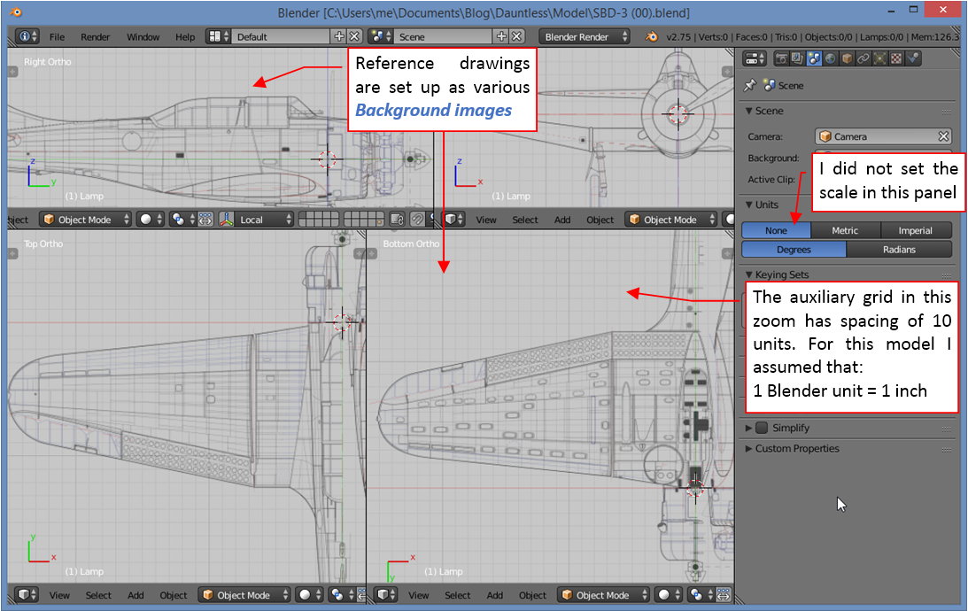
Although Blender allows for arranging the reference drawings on the three perpendicular planes like in the 3D Max, I prefer the alternate way: the Background images feature. Using them, I can assign appropriate image to the corresponding view, and simultaneously use all the six views (bottom, top, left, right, front, rear). They appear just when I set appropriate projection.

This is also the moment to determine the “scale” of this model. Because on the SBD drawings that I have all the dimensions are in inches, I decided to assume that 1 unit in this Blender scene = 1 inch on the real airplane. However, I have no experience with the Blender Units setting, so I left them set to None. If you want to check details of this setup, here is the original *.blend file.

I started modeling the wing by forming the contour of its root rib. (For this purpose I draw the shape NACA2415 airfoil on the reference drawing). I smooth most of the model meshes with Subdivision Surface modifier (it uses the classic Catmull-Clark scheme). The shape of a single edge loop smoothed by this scheme is a piecewise Bezier curve (or, if you wish, a NURBS curve – this is just an alternate math representation). The edge vertices are its control points, so I can easily shape this contour. You can see the result in teh figure below. (In this image you can see that the vertices lie on the rib contour, because the mesh drawing mode there was switched to draw the resulting surface):

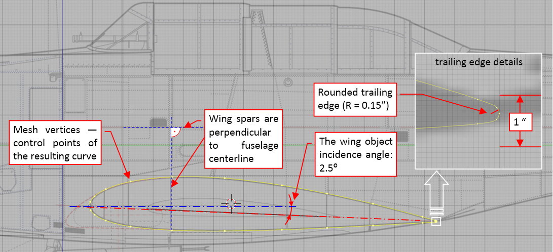
The theoretical shape of the NACA-2415 airfoil has a thin, sharp trailing edge. However, in the real airplane it was rounded because of the technological reasons. I tried to determine its radius from the photos. As you can see in the enlarged fragment of the picture above, it forms a small wedge with rounded corner. It is shaped using five vertices. (Their number corresponds the number of the leading edge vertices — I will explain the reason further in this text). The Dauntless inherited many solutions from its Northrop Delta lineage. For example — its wing spars are not perpendicular to the wing airfoil chord. Instead, they are perpendicular to the fuselage centerline. (In the SBD, like in the earlier Northrop designs, the center wing panel and the fuselage form a single unit.  I suppose that it was easier to put together the wing spars and fuselage bulkheads when they shared the same technological bases).

To provide as many “technological bases” for my model as possible, the X axis of the wing object is parallel to the wing chord. I can set it “in the Northrop way” by setting the object incidence angle to 2.5⁰. In this position I can work with the wing mesh, moving vertices along the global coordinate axes (i.e. the axes of the fuselage), and then switch to the local wing object axes when needed.

In the next step I formed the basic wing trapeze. I did it by extruding the wing root edge, and shrinking the airfoil located at the wing ti:

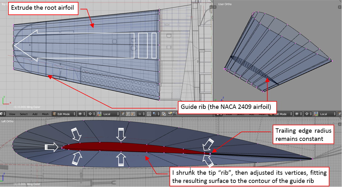
Now you can see why I draw this wing section on the plans without dihedral. This drawing would be useless if it depicted the wing “properly”! From the reference images and descriptions it seems that the wing tip had the NACA-2409 airfoil. In the first approximation I scaled down the rib of the tip, fitting it to the reference drawing. (To fit this mesh to the front view I temporarily rotated the wing by its dihedral angle — 10⁰ 8’ — as in the picture below). However, although scaling down the original NACA-2415 coordinates produces the NACA-2409, it does not work precisely for the airfoil shape recreated with the Bezier curves. To fix these small differences I prepared an auxiliary “guide” rib of the NACA-2409 airfoil and placed it in the tip. (see the picture above). Then I modified the wing tip airfoil, fitting the wing surface to the contour of this guide rib (you can see on the picture that it minimally protrudes from the wing – as a very thin line).

Then I rotated the root airfoil, adjusting it to the wing dihedral:

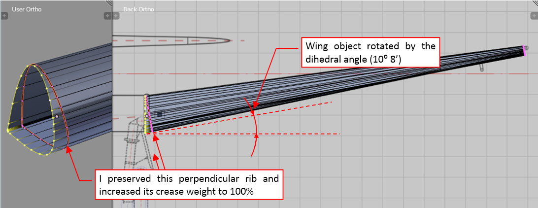
In the SBD Dauntless all the wing ribs were perpendicular to the wing chord plane, except the root rib of the outer panel. To easily insert properly oriented ribs in the middle of this wing, I inserted another rib after the skewed wing root rib. It is perpendicular to the chord plane. I marked this rib edge as “sharp” (by increasing its Crease weight to 100% —you can recognize it on the picture by different edge color). In this way I ensured that the skewed root rib has no influence on the new edges I will add in the middle of this mesh.

In the Catmull-Clark subdivision surfaces, you can use the Crease weights to obtain a local sharp edge or to separate a mesh fragment from the influence of the outer mesh vertices. I learned this method from a Pixar paper, presented on SIGGRAPH 2000 by Tony DeRose. (Before I started my first model, I studied the subdivision surfaces math, to know better properties of the basic “material” used in the digital modeling).

I had an occasion to learn that it works as expected in the next step: forming of the rounded wing tip. First I inserted into the tip area a few new ribs (using the Loop Cut command). Then I started bending their trailing and leading edges, to finally join them into an arch:

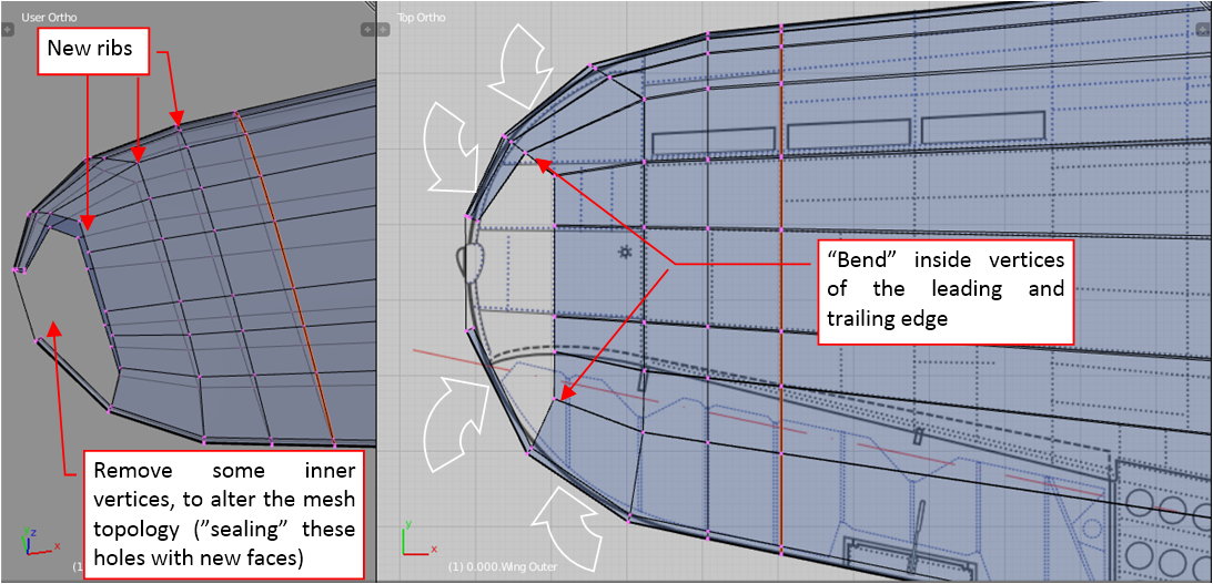
As you can see in this picture, I also removed some of the internal mesh faces. I did it because I had to alter the topology of this area. (It is easier for me to determine the new faces when the old ones are removed).

Note that it was a good idea to have the same number of vertices on the trailing and leading edge. Now I can easily join them at the wing tip.

Figure below shows the resulting surface:

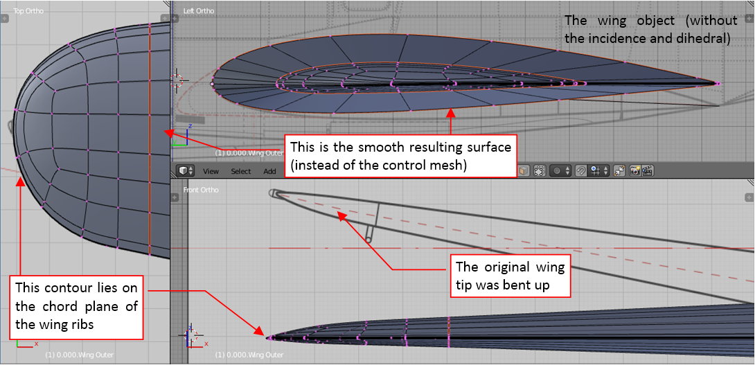
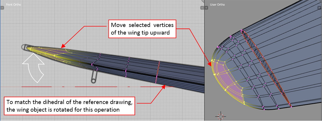
Note that the wing tip edge lies on the wing chord plane. As we can see from the reference drawing, in the real airplane the wing tips were slightly bent upward. We can easily obtain such an effect by moving upward (and slightly rotating) last vertices of the tip:

In the figure below you can see the control (i.e. not subdivided) mesh of this wing:

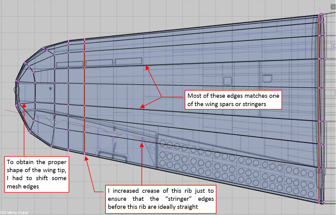
Note that I tried to align as many “longitudinal” mesh edges as possible to the stringers and spars visible on the reference drawing. This will be extremely useful when I draw skin details on the wing surface unwrapped in the UV space (for texturing).

In this source *.blend file you can check any detail of the mesh presented in this post. The next post will describe further steps of the wing modeling: separation of the aileron and forming of its bay in the wing.

This blog provides just an overall picture of the process. If you want to learn more about Blender, digital aircraft modeling and subdivision surfaces, see this guide: “Virtual Airplane” (vol. II).

  • Member since
    June 2013
Posted by bvallot on Sunday, July 26, 2015 11:00 AM

Jaworski, this is incredible!  And incredible timing as well.  I've just begun working on a Dauntless myself and I've been pooling together sources to up the detail in my build.  What a wealth of knowledge right here. =]  One thing I haven't found with any ease are pictures of the -3 engine and the parts within the mounts.  Would you have any references on that or know where to find them?

I'm really enjoying this thread.  I'll be watching.  =D

On the bench:  

Tamiya F4U-1  Kenneth Walsh


  • Member since
    June 2014
Posted by Witold Jaworski on Sunday, July 26, 2015 2:51 PM

You are welcome! :)

I can see no special differences in the R-1820 engine between subsequent SBD versions. Here are:

R-1820 engine manual (contains photos and drawings):

Some photos of the Bendix-Stromberg carburetor (not covered by the R-1820 manual)
Hamilton Standard Propeller governor details (not covered by the R-1820 manual):


So far I have not found too many pictures of the elements inside engine mounts of the SBD-3:

The details from the later version (SBD-5) can be also useful: the SBD-3 was simpler: if you remove the filtered carburetor air ducts it will be still usable:

Let me know if you will find more photos of this area...

  • Member since
    June 2013
Posted by bvallot on Monday, July 27, 2015 12:09 AM

This will definitely be of some help.  Many thanks! =]

On the bench:  

Tamiya F4U-1  Kenneth Walsh


  • Member since
    April 2015
Posted by Mark Lookabaugh on Friday, July 31, 2015 10:00 PM

I hate to break up the continuity of this thread... but I just can't help myself.  

I am in awe of your attention to detail.  You are amazing.

  • Member since
    June 2014
Posted by Witold Jaworski on Saturday, August 1, 2015 2:23 PM

Mark, thank you very much!

(Do not worry about the thread continuity - your feedback is as important as my posts that report the progress of the work Smile)

  • Member since
    June 2014
Posted by Witold Jaworski on Saturday, August 1, 2015 2:32 PM

In the previous post I have formed the general shape of the Dauntless wing. Now I will work on its trailing edge, separating the aileron and flaps. They were attached to the internal wing reinforcements. These reinforcements were distributed in parallel to the trailing edge:

In the first step I will split the wing mesh along this line. However, before I do this, let me mention a certain geometrical effect which can be surprising for many modelers. (Frankly speaking: it was also surprising for me — I knew that such an effect exists, but I thought that its results can be neglected for this wing area).

When you place on the wing a plane shaped like the "cutting line" shown on the picture above (see below, left), you will discover that the resulting intersection edge on the wing surface forms a curved contour (see below, right):

The curve on the wing tip is not a surprise, but why the intersection of the flat plane and the wing trapeze (i.e. the line between point 1 and 2) is also curved? The answer is: because this wing is like a section of an elliptic cone. The only straight line on the cone surface connects its base and apex. Any other direction (like our cutting plane) produces a curve. When the curvature of the wing airfoil on this area is low, the deviation from the straight line can be neglected. However, in this wing it produces a 0.23” deviation at the aileron root rib. You had to adapt contours of the spars and stringers used there.

Obtaining such a gently curved shape on a relatively long element is difficult from the technological point of view (i.e. costly). It can be applied if the high performance is on the stake (as in the Spitfire case). However, even the Spitfire designers had to make a compromise with the workshop and made the bottom of their wing flat. (In this way they provided a technological base).

What could do a pragmatic Northrop (then Douglas) designer in such a case? I have no direct photographic proof, but it seems that they approximated this shape with two straight segments. They are split at the aileron root section:

In the next post I will show you that in this wing each of these two segments was made in a different way. The flaps were attached to a reinforced vertical wall (a kind of a partial spar), while in the front of the aileron there was a lighter structure matching the shape of the aileron leading edge.

After these deliberations we can cut off the trailing edge from the win:

(I did it in two steps. In the first step I created a new edge along the intended split line, using the Knife tool. In the next step I separated the rear part of this mesh into a new object).

We will deal with the red elements in the next post. In this post let’s recreate wing details along the flaps and aileron bay:

The ultimate edges of aileron bay are located a little bit further than the “reinforcement line”. I extruded them from the original mesh.

When a part of the original control mesh is removed, the shape of the resulting object can have small deviations from the original shape of the complete wing. Thus before I separated the trailing edge I copied the complete wing into an auxiliary, “reference” object. Now I am using it to ensure that all these newly extruded vertices lie on the appropriate height:

On the picture above you can see solid red areas around the modified vertex. This is the result of the approximation of the curve section (the flap hinges have to be straight lines).

To determine exact shape of the aileron bay edges I placed an auxiliary “stick” along the aileron axis, as well as some circles around it. The radii of these circles match the shape of the aileron leading edge (+ the width of the eventual gap — see picture below, bottom left). Then I set the view perpendicularly to this aileron axis object, and used auxiliary circles to determine the shape of the aileron bay edge:

Finally I closed the aileron bay with a curved wall that matches the shape of aileron leading edge:

In this source *.blend file you can check all details of the mesh presented in this post. The next post will report further progress on the wing trailing edge details (I will form and fit the aileron).

  • Member since
    June 2014
Posted by Witold Jaworski on Saturday, August 8, 2015 12:08 PM

In the previous post I have modeled the aileron bay in the SBD Dauntless wing. However, it was one of the cases when I followed my intuition and the mathematical precision of the computer models instead checking how this detail looks in the real airplane. So let’s do it now. I have reviewed many photos. The figure below shows the one which is the most useful (made by my friend in 2014 in one of the air museums):

We can see here that the flaps are attached (via a very long hinge) to a reinforced structure which resembles a spar. It ends at the first aileron hinge. On the other hand, the aileron is mounted on three “point” hinges which protrude from the ribs. Thus the curved sheet metal that closes the aileron bay has much lighter structure, because it is merely a cover. It is riveted to the ribs and other wing skin panels. The “sharp corner” at the upper edge of the aileron bay is obtained by a fragment of the upper wing skin that overlaps (by about half of inch) the bent, rounded edge of the internal wall.

I recreated in my mesh the auxiliary spar along the flaps and the fragment of the wing skin that overlaps the upper edge of the aileron bay:

I will model the bent upper edge of the internal wall later, during the detailing phase. The lightening holes in the spar will not be modeled. For such less important openings I will use transparency textures.

At the beginning of the previous post I cut off the wing trailing edge. Now I split it into two objects: the aileron and the flaps. Then I started to work on adapting the aileron mesh. First I simplified its topology: I slid its upper longitudinal edge forward, where the curved leading edge begins (Figure a), below). I do not need its bottom counterpart, so it will disappear. In the effect the aileron cross section resembles a triangle, as in the real airplane. (Such simplifications of the theoretical trailing edge geometry were common in this aircraft generation).

 '

To form the curved shape of the aileron leading edge I extruded vertically from its bottom edge two face rows (Figure b), above). Then I closed the remaining gap with another row of faces.

After small adjustments of their vertices at the wing tip I obtained the rounded shape of the aileron leading edge:

Then I did some further adjustments, checking if the gap between the aileron and the wing is wide enough (0.2”) for the whole aileron rotation range (from -10⁰ to +17⁰). You can see the result in the figure below:

However, comparing this result with the photos, I discovered that I fitted it too tightly! What’s more, I also noticed differences in the shapes of the aileron tip and its bay between various restored aircraft:

The outer wing panels were the same in all the SBD versions (at least their external details — see this post) — so I cannot explain these differences as the differences between various aircraft versions. Well, it seems that one of these restored aircraft was modified afterward. But which one?

Restored aircrafts are great resource of information for all modelers. However, some of them contain various modifications. Most of such differences you can find in the airplanes restored before 1990. Since that time the average level of restorations has significantly improved.

To determine which case is wrong, you have to look at the archival photos:

In the picture of a factory-fresh SBD-1 you can see that the tip of the aileron was curved. Nevertheless, I had to widen the gap between the aileron and the wing tip, reproducing the case I can see on the archival photo:

In this source *.blend file you can check all details of the model presented in this post.

In the next post I will recreate the flaps.

  • Member since
    June 2014
Posted by Witold Jaworski on Thursday, August 13, 2015 1:45 PM

Summer break: I am leaving on vacation (away from the computer for two weeks). I will describe further progress of my work on the SBD Daunless on August 29th.

  • Member since
    June 2014
Posted by Witold Jaworski on Saturday, August 29, 2015 1:44 PM

Perforated split wing flaps were the hallmark of the SBD Dauntless. Their inner side was reinforced by the “grid” made of stringers and ribs. Because these flaps were often wide open — during landing or in dives — I have to recreate their internal structure. In this and the next post I will describe how I did it.

All the SBD flaps had fixed chord (they were made from perforated sheet metal of rhomboidal shape). After studying many photos I assume that all their ribs have the same size and shape — also the parts attached to the trapezoidal, outer wing section. It seems that Douglas factories built all five flaps of the SBD in the same way, using unified components. The flaps for the external wing panels had to be twisted a little during riveting — most probably on appropriate mounting pads. The trailing edge of the upper flap is the trailing edge of the whole wing. It was a thin wedge, profiled from a sheet metal and riveted to the flap skin:

(Similar wedge is riveted to the upper skin of the center wing — see the picture above). The chordwise contour of these flaps looks flat on the photos. In fact there is only a small difference (less than 0.2 inches) between the theoretical contours of the wing airfoil and a straight line on the area around the trailing edge. I think that for the designers such a technological simplification was not a big deal — they had already made a more serious modification by perforating the flaps.

I started building the SBD flaps by creating their upper and lower planes. (I created them by simplification of the mesh fragment that I previously cut off from the wing). I used the Solidify modifier to give them thickness of a sheet metal. (I used this modifier for all parts which I will create in this post). Then I added the wedge (another object) along their trailing edge:

I started this wedge as a single contour, which I extruded along the whole span of the flap. Because of the trapezoidal shape of this wing, I had to twist a little the outer end of this wedge, fitting it better to the upper flap. Then I shortened the trailing edge of the bottom flap, fitting it into the wedge when it is closed.

When it was done, I added the main “spar” of the flap (in fact it was a U-shaped stringer). I did it in the same way as I created the trailing edge: shaping the profile, then extruding it lengthwise:

Once extruded, I had to rotate this object and twist its end, lying its outer edges on the inner surface of the flap skin. To facilitate this process I assigned this object a contrast, red color.

While fitting this spar, I discovered that the twisted, four-vertex face of the flap skin has small elevation along its diagonal (as in picture above). It is not something “real” — just an effect of the internal decomposition of all quads into triangles made by Blender.

To eliminate this artificial effect I had to divide this sigle, large face into several smaller pieces:

It minimized the influence of Blender internal “triangulation” and allowed me to properly fit the stringer to the flap. As you can see in the picture above, the end profile of this spar is twisted, following the twist of the flap skin.

After the first stringer I created in a similar way two other reinforcements on the flap edges:

As you can see, I used two clones of the rib contour. (I needed them to determine slopes of the front and rear reinforcements in the side view — as in picture above).

When the flap lengthwise reinforcements are in place, I can add the ribs:

All the internal ribs are clones of a single mesh. The external ribs have the same contour, but each of them has its own mesh (because they do not have the cutout for the central spar, as the internal ribs). These flap ribs have quite complex shape, but I managed to keep their mesh quite simple. It was possible, because a part of this complexity (the sheet metal thickness, rounded edges) is created by the Solidify and Bevel modifiers.

When the ribs were in place, I added the last stringer. It was a “L”-shaped beam:


Modeling internal structures of the flap forced me to carefully measure anew all of its details, especially the width and location of its spars. In the effect you can see that my wing drawings are not as precise as you could expect:

In this source *.blend file you can check all details of the model presented in this post. In the next post I will continue my work — this time on the upper flap.


  • Member since
    March 2012
  • From: Corpus Christi, Tx
Posted by mustang1989 on Monday, August 31, 2015 8:28 PM

Man....this aint model building. This is freekin' engineering!!! Nice job!! And that's putting it mildly bud!


 Forum | Modelers Social Club Forum (proboards.com) 

  • Member since
    June 2014
Posted by Witold Jaworski on Saturday, September 5, 2015 2:24 PM

Thank you!

I simply cannot resist temptation to recreate most of the details I can see on the photos! For the first time you can have a "material" which allows you to recreate all these sheet metal elements as thick as they were in the reality... In this work your patience is the only limit :).

  • Member since
    June 2014
Posted by Witold Jaworski on Saturday, September 5, 2015 2:29 PM

In this post I will create internal structure of the upper split flap. Structures of both flaps are similar, thus I started this job by copying stringers from the bottom flap, finished in the previous post:

Every copied stringer is a duplicate of its counterpart from the bottom flap (I just used the negative scale: -1). I had to rotate these objects, placing them on the internal side of the upper flap skin. I copied the internal ribs in the same way (see picture below). (All of them are clones, which use the same mesh):

As you can see in the side view (see in the picture above, upper left), there is just a small vertical distance between the last ribs of the upper and lower flap (i.e. at the aileron). This is the thinnest place of this structure.

At the trailing edge of the upper flap there is the profiled wedge (I described it in the previous post). The upper flap is little bit wider (it has longer chord length than the bottom flap). Because of this the ribs of the unified size used in these flaps are too short to reach the closing wedge (see picture above).

We can observe this effect on the photos. To make these ribs longer, designers added at their ends small “U”-shaped profiles (see picture below):

I recreated these elements in my model (see in the picture above, right).

The upper flap has a cutout in its inner edge. Thus there is “one and half” of the external rib here:

I recreated this structure in my model and modified the mesh of the upper skin:

These flaps were attached to the wing by two long hinges. I recreated them as two very long cylinders and placed between the flaps and the wing:

Now, when I rotate the hinge along its local Z axis, the whole flap rotates, like in the real aircraft:

This is a preparation for the future animation of this movement (during the detailing phase).

In this and the previous post I built the split flaps and their basic skeleton. I recreated these ribs and stringers because they are visible when the flaps are extended. The additional benefit of this work was the verification of my reference drawings. (Now I know that I have to shift a little the perforation and rivet seams on both flaps. I will do it when I prepare their textures). However, on this stage it is too early to finish all remaining details of these flaps. It still may happen that I will discover something which will force me to modify the geometry of this wing and its flaps. Thus in the picture below I marked what I prefer to postpone until the detailing phase:

As you can see in this picture, I will create the openings in the flap skin later. At this moment I am going to recreate them using the same technique as for the lightening holes: textures (the bump map and transparency map). However, if this idea fails, I will model these openings in the flap skin mesh. (This method requires much more time than the textures).

In addition to these openings I will also recreate all the minor details of the flap structure. For example — I will split the “L”-shaped auxiliary stringer between the ribs. I have also to split the flap forward reinforcements into separate segments.

The complex system of the flap actuators will be also a challenge for the detailing phase (however, I already analyzed how it works).

In this source *.blend file you can check all details of the model presented in this post. In the next post I will create the fixed slats and finish this outer wing panel for this “general modeling” stage of work. Of course, I will work on it again later, during texturing and detailing.

In the next post I will add fixed slats, completing this outer wing section.

  • Member since
    June 2014
Posted by Witold Jaworski on Saturday, September 12, 2015 12:34 PM

In one of the previous posts I showed the details of the aileron bay. Now I separated the corresponding wing mesh fragment into a new object. I bent its upper edge like it was depicted on the photo:


On some photos I could see that this wall was built of two pieces of sheet metal. Their seam was located below the aileron pushrod.

The reason for such split became obvious after the comment I received from one of the readers (thank you, Brian!). It happened that a few weeks ago he visited the Yanks Air Museum in Chino, and had an occasion to examine wings of their SBD-4. He reported that while the bottom edge of the aileron bay is a straight line, the upper edge has a break at the pushrod. The difference from the straight line at this point is about 0.1-0.2 inches. Checking this tip, I examined photos of this particular SBD-4, then I verified photos of the other SBD version:


This nuance of the aileron edge is hardly visible in a perspective view. It explains why I missed it studying the photos!

Finally I recreated this detail in my model:


(Doing it, I had to modify shapes of three objects: the wing, the rear wall of the aileron bay, and the aileron).

I could not resist the temptation to recreate the rounded corner of the wing skin at the aileron root:


Frankly speaking, I should model such a thing during the detailing phase. I allowed myself to use some n-gons (faces that have more than 4 vertices) here, because this surface is flat so these n-gons will not deform the smoothed result.

However, looking on the photo above I noticed that the aileron bay edge seems to lie on the same line as one of the rivet seams on the flap. (The seam that runs along the rear edge of the hinge reinforcements). So it was on the reference drawing. However, do you remember that I had to modify these flap reinforcements, shifting them forward (in this post)? So now I know that this rivet seam is in another place on this flap, different from the place where you can see it on my drawing. Now I have to update accordingly the location of the aileron edge!

To preserve its vertical shape, I did it by two rotations: first I rotated it along Z axis:


Then I had to make a small rotation along Y axis (along the same pivot point), elevating these faces back onto the wing surface.

The updated layout of the flap ribs and struts means that I will have to move forward not only the rivet seams, but also the rows of the circular openings placed on the flaps (I mentioned it in one of the previous posts). What’s interesting, the auxiliary “L”-shaped stringers on the upper and lower flap have different chordwise locations. In the result, the last row of the holes in the upper flap does not match its counterpart on the bottom flap (see picture above).

The last detail I will recreate during this stage of work is the fixed slat. It requires six openings in the wing skin: three on the upper surface and three on the bottom surface. I did not modify the wing mesh for this purpose, because additional edges around these openings would seriously complicate its topology. I decided to create them in another way: it may happen that ultimately I will make these holes using transparency textures, but for now I will do it using the Boolean modifier. First I prepared an auxiliary object — the “cutting tool”


I set the wing as its parent, and placed on a hidden layer. Then I used a Boolean modifier to dynamically cut out these openings in the wing:


Note that I placed the Boolean modifier after the Subdivision Surface modifier, to cut these holes in the resulting, smooth wing surface. As an additional bonus, this modifier also creates their internal walls (they come from the auxiliary object).

Although the “rib” walls obtained in this way are OK, I decided to create the front and rear walls of this slat as a separate object. Why? Because it is easier to modify its shape when it is not split into three “boxes”, as the “cutting tool” object is:


I will join all these internal faces of the slats during the detailing phase. Currently I am leaving them in the current state, just in case I will have to modify the wingtip geometry.

This was the last element of the outer wing panel I wanted to create during the “general modeling” phase. I will recreate all of remaining parts (landing light, approaching light, Pitot tube, aileron axis arms, etc.) later, during the detailing phase.

In this source *.blend file you can check all details of the wing presented in this post.

Note: When you open this file, the Boolean modifier may not work properly. The slats will appear when you enter the Edit mode of the wing object, then switch back to the Object mode (i.e. select the wing panel and press twice the [Tab] key). It seems to be a minor bug in Blender: it happens when the object having the Boolean modifier is simultaneously the parent of the “cutting tool”. (More on various modeling issues you can find in Vol. II and Vol. IV of the "Virtual Airplane" guide).

In the next post I will start working on the centerwing. It will be occasion to find another parent for the “cutting tool” object, resolving the issue of disappearing slats.

  • Member since
    June 2014
Posted by Witold Jaworski on Saturday, September 19, 2015 2:05 PM

On the first glance the SBD center wing section seems to be a simple rectangular (i.e. constant chord) wing, with modified leading edge:

Posted Image

However, the landing gear openings visible on the photo can be difficult to recreate in a mesh smoothed by the subdivision surface modifier.

Additional photos from one of the SBD restorations made by Vulture Aviation in 2012-2013 reveal that the fuselage was mounted on the top of the wing (see the a) picture below):

Posted Image

A part of the upper wing surface was simultaneously the cockpit floor. Note the rectangular cutout in the middle of the leading edge. The SBD had a small window on the bottom of the fuselage, in the space between the two root ribs.

On the photo of the bottom of this wing (as in the b) picture, above) you can see that these root ribs had a modified airfoil shape: it bottom contour has a straight edge from the leading edge to the main spar.

I started to form the center wing section by preparing the single curve of its external rib. (I copied it from the root rib of the wing reference object, which I used during modeling of the outer wing panel):

Posted Image

I think that creation of these large landing gear bays (as the first picture in this post) will require a lot of modification in the wing mesh. Thus I decided to separate the mesh fragment that contains these openings (from the leading edge to the main spar) into a separate object. (It is always easier to modify topology of such a medium-size mesh part, than the whole wing). To ensure a smooth, invisible seam between this forward and the rear part of the wing, I had to accordingly prepare the control polygon of the initial airfoil. I added an additional point on each side of the vertices located above and below the spar line:

Posted Image

What’s important, such three points have to be collinear. The resulting subdivision surface “touches” the middle point of such a fragment of the control polygon, and it is tangent in this point to these two adjacent control polygon segments. (This is just one of the mathematical properties of the Catmull-Clark subdivision surfaces, which are implemented in Blender).

However, these four new control points altered the shape of the airfoil curve. Now I have to fit this shape to the original NACA-2415 airfoil of the outer wing panel:
Posted Image

Fortunately, the Catmull-Clark curves/surfaces have another property similar to the NURBS: so-called local change. Their formula ensures that influence of a single control point does not exceeds two subsequent segments of the control polygon (two segments in both directions — see picture above, right). It is easier to focus on the modified mesh fragment, when you know this rule.

Once the initial rib shape fits the outer panel, I can extrude it forming the center wing section:

Posted Image

To shape the leading edge I had to stretch a little bit the forward part of this mesh. As you can see (in the picture above), I placed this new edge loop in the place of the wing root rib.

However, comparing the resulting object with the photos I discovered that the leading edge of the center wing section should have constant radius (at least approximately):

Posted Image

In this way I have found another error in my reference drawing: the wrong shape of the root airfoil:

Posted Image

The tangent direction at the wing spar differs from the direction estimated on the drawing, thus the bottom, straight segment of the root airfoil has a slightly different slope. The leading edge is much thicker than I draw on these plans.

Adapting the well-known von Moltke’s sentence: “no plan survives contact with the enemy” to this situation, we can say that “no scale plans survive contact with their 3D model”. :)

I created a first approximation of the main wheel (it lacks the details) to check if it fits into the space between the leading edge and the main spar:

Posted Image

When I was sure that the shape of the wing is OK, I separated the forward part of this mesh (by splitting it along the main spar). As you can see (in picture above, right) these two parts join in a seamless way. It was quite simple to prepare such an effect in the initial curve by adding additional control points (as I described in the beginning of this post). It would be much more difficult to introduce similar modifications into the extruded mesh.

If you want to learn more about properties of the Catmull-Clark subdivision surfaces, as well as the details of the modeling workflow, see Vol. II of the “Virtual Airplane” guide.

In this source *.blend file you can check all details of the wing presented in this post.

In the next post I will create the opening for the landing gear.

  • Member since
    June 2014
Posted by Witold Jaworski on Saturday, September 26, 2015 1:43 PM

In this post I will cut out the opening of the landing gear bay in the wing. In the SBD Dauntless its shape consists a rectangle and a circle:

Posted Image

However, when you look closer, you will notice that the contour of the main wheel bay is not perfectly circular. There is a small deformation of its shape on the leading edge (see picture above). I think that it looks in this way because of the technological reasons. Another feature of this opening is the fragment “cut out” in the bottom part of the fuselage, below the wing. (We will make it when we will form the fuselage).

I started by applying all the information that was confirmed by the general arrangement drawing and various technical descriptions: the main wheel used 30”x7” tire. Its center was placed 18.5” from the firewall (measured along the global Y axis):

Posted Image

The X coordinate of the wheel center can be determined by the location of the root rib (10”) + small gap + tire radius (30”/2) ≈ 26”.

Then I tried to put around the main wheel a test contour of the opening in the wing:

Posted Image

Initially I thought that I will recreate this opening by embedding a subdivided octagonal hole in the wing mesh, as I did in my P-40 model (see Vol. II of the “Virtual Airplane” guide).

A subdivision curve based on an octagon produces nearly perfect circle. It does not matter if vertices of this octagon lie on different depths — as long as they form an octagon in the vertical view, the curve based on such a control polygon looks like a circle in the vertical view. (The mathematicians call this property “projective invariance”, it also applies to the NURBS curves). When you know it, it is much easier to model various mechanical shapes.


However, when I created an appropriate octagon around the wheel, I discovered that one of its vertices lies outside the wing mesh (see figure a), above). You cannot compose such a contour into the wing. Therefore I decided to create this opening using another Boolean modifier, as I did in the case of the fixed slats (described in one of the previous posts). I prepared the basic contour of the “cutting tool” — a smooth circle based on a 16-vertex polygon (as in figure b), above).

The fragment of the main wheel opening that “touches” the wing leading edge seems to be flatten a little (see the first picture in this post). To obtain such an effect I rotated the “cutting tool” object (the ring) by a few degrees so its Y axis was perpendicular to the leading edge. Then I shifted a little the single edge of this ring along the Y axis, fitting it into the wing:

Posted Image

By small movement of these two vertices I was able to precisely recreate the shape of this opening visible on the photos:

Posted Image

If I do not want to get the inner part of the “cutting ring” inside the resulting opening, I have to assign to this wing mesh a sheet metal thickness (using the Solidify modifier – as in picture below):

Posted Image

Because the forward and rear part of the wing are separated, I can use this Solidify modifier only in the front part. In this way I do not increase the polygon count of this model with unnecessary faces.

As you can see in the picture above, I also created a second “cutting object” — a box. I will use it to recreate the rectangular opening around the landing gear leg. Both of these tool objects are located on a single layer (9) which will be hidden during rendering. Their parent is the rear part of the center wing section (to avoid dependency conflict with the front part of the wing).

Finally I assigned both of these “cutting” objects to the Boolean (Difference) modifiers of the wing skin (The same method as used for the fixed slats). You can see the result in picture below:

Posted Image

It would be quite difficult to recreate such an opening by altering the control mesh of the wing skin. It also would make its shape more complex, and difficult to unwrap in the UV space (for the textures).

The openings created by Boolean modifiers have another advantage: it is very easy to modify their contours. I had to do this just after I created these holes. I discovered that I made minor error in the reference drawing: the landing gear leg opening should lie a little bit back. (Its centerline should pass through the landing gear wheel center

Posted Image

All what I had to do was to shift back the auxiliary box object, which creates this opening. So easy!

On the other hand, I observed small shadows caused by triangular faces created by the Boolean modifiers along edges of this opening. It was impossible to remove them in the typical way — using the Auto Smooth option or the Edge Split modifier. The only solution was to increase (from 2 to 4) the level of the Subdivision Surface modifier assigned to the wing surface object. It increased 16 times the number of resulting smooth faces created from this mesh. Fortunately, I split the wing into two parts, so I could set keep such a dense mesh only around the area where it is needed.

In this source *.blend file you can check all details of the wing presented in this post.

In the next post I will create main spars and ribs, visible inside this opening.

JOIN OUR COMMUNITY!

Our community is FREE to join. To participate you must either login or register for an account.

SEARCH FORUMS
FREE NEWSLETTER
By signing up you may also receive reader surveys and occasional special offers. We do not sell, rent or trade our email lists. View our Privacy Policy.