SEARCH FINESCALE.COM

Enter keywords or a search phrase below:

SBD Dauntless

73510 views
196 replies
1 rating 2 rating 3 rating 4 rating 5 rating
  • Member since
    June 2014
Posted by Witold Jaworski on Saturday, February 27, 2016 2:02 PM

Watchmann

You're pretty good at pushing verts, Witold!  I'm envious. :D

Thank you! :)

Anyway, I published all my know-how in this guide, so you can easily adapt my methods!

  • Member since
    June 2014
Posted by Witold Jaworski on Saturday, February 27, 2016 2:03 PM

SBD Dauntless had a radial engine hidden under typical NACA cowling. The Douglas designers placed its carburetor air intake on the top of this cowling, and the two Browning M2 guns behind it. In the result, the upper part of the SBD fuselage, up to the pilot’s windscreen, had a quite complex shape:

Posted Image

I am sure that I will tweak this shape multiple times before I reach the most probable compromise between all the reference photos I have. It will be much easier to do it by modifying a simple mesh instead of the complex topologies of the final cowling. Thus I decided to create first a simpler version of this fuselage section and adjust it to the all of the available photos. I will describe this process in this and the next post. Once this shape “stabilizes”, I will use it as the 3D reference in forming the ultimate cowling. Because I am going to recreate all the internal details of the engine compartment, I will create each cowling panel as a separate object.

I started by creating the three key contours of the NACA cowling:

Posted Image

Section 1 (see figure "b", above) was a perfect circle, while section 2 was a little bit higher than wider (see figure "a", above). Ultimately section 3 was a regular ellipse. Note that all these sections have the same number of the vertices (32).

Once I created these three edges, I connected them using three arrays of faces. Them I added in between (using the Loop Cut command) three additional edge loops. I needed them to form the curved forward part of this cowling:

Posted Image

As you can see above, I fit the silhouette of this NACA cowling to the reference photos. This is a photo of the SBD-5, so I moved this cowling forward by 3.5” (see in this post about differences between SBD-3 and SBD-5 cowlings Figure 4-6, for the explanation).

When I finished the NACA cowling, I formed the basic shape of the next fuselage section:

Posted Image

I created this part in the same way as the previous one. First I copied and shrunk the last NACA cowling edge, creating the gap for the outgoing air. Then I copied the firewall edge, and joined these two edges by an array of new faces.

In the next step I extruded the upper part of this surface, creating the section below the windscreen:

Posted Image

It is a “linear” continuation of the previous fuselage segment. I fitted its sides to the mid-fuselage, which I formed some months ago.
The next elements are the “bulges” that covered breeches of the Browning M2 guns. In this ‘quick and dirty’ approximation I formed them from a separate mesh patch (see figure "c", below):

Posted Image

Of course, I verified their shape on the available photos, as you can see in figure "c", above.

This comparison revealed, that the intersection lines between these “bulges” and the main fuselage require some improvements: they have to resemble straight lines:

Posted Image

To obtain such an effect, I had to decrease the upper radius of the last bulkhead (figure "b", above). In such a simple mesh it required just to move a few vertices. If I had to perform such an operation on the final panels, it would be much more difficult!

In the front of the gun barrels there were long recesses in the NACA cowling. The outer edges of such a feature are always a tough test for the model, because they depend on the proper shape of the both intersecting elements. First of these objects is the NACA cowling, the second is the shape of this recess — a cylinder in this case:

Posted Image

I cut these openings using a Boolean modifier. Figure below shows the result:

Posted Image

In figures "b" and "c", above, you can see the evaluation of the obtained contours. They seem to fit the borders of the recesses on the reference photos. (There are minor differences, but I suppose that they are results of the rounded edges of these features.

In this source *.blend file you can evaluate yourself the model from this post.

In the next post I will continue shaping this first approximation of the engine cowling.

  • Member since
    January 2016
  • From: Salt Lake City, Utah
Posted by Sailor Steve on Saturday, February 27, 2016 3:31 PM

I don't want to interrupt your thread, but I was thinking about how earlier on you said that there were others who are better at this than you.

I have my own little corner of my base website where I show off my plastic models. Everybody there tells me how brilliant I am and wonderful my models are. I reply that not one of them could even compete in a contest, let alone win. All I see is the warts.

What I'm trying to say is, you say there are others better than you. Maybe, but I don't see it. I think your work is brilliant, and I've read this entire thread at least once through, and I keep coming back to see what's next. Keep up the good work.

  • Member since
    June 2014
Posted by Witold Jaworski on Saturday, March 5, 2016 2:33 PM

Sailor Steve, thank you very much!

Just one thought about this fragment:

Sailor Steve

(...) you say there are others better than you. Maybe, but I don't see it.  (...)


Fortunately, I am able to point web sites of these modelers. You can find them at the begining of this introduction (see the 'Motivation' section). There is also a small forum of the 3D modelers, where you can find some interesting pieces.
  • Member since
    June 2014
Posted by Witold Jaworski on Saturday, March 5, 2016 2:35 PM

In this post I will continue my work on the engine cowling. I started it in the previous week by forming a “first approximation” of the forward part of the SBD Dauntless fuselage. Now I will create the last elements of this auxiliary object.

First of them are the covers around the M2 gun barrels. They were hinged around their inner edges, and their cross-section varies from a semi-circle at the NACA cowling to a flat line at the firewall:

Posted Image

I started forming this cover from a conic cylinder, created around the gun barrel:

Posted Image

Then I cut out its bottom part and flattened its end section along the side “bulge”:

Posted Image

I formed it to resemble the gun barrel covers as they were in the SBD-1..-4s. Studying the photos I identified that this detail looks a little bit different in the SBD-5 and -6:

Posted Image

As the last element of this auxiliary object I will form the windscreen. I need it for determining the ultimate slope of the “bulges” around the breeches of the M2 guns, and for checking the shape of its intersection with the fuselage. (If I did it later, it could reveal some unexpected surprises about the fuselage geometry, resulting in additional work).

I used the reference photos to determine the basic radii of the canopy hood and the windscreen cross sections:

Posted Image

(In this aircraft canopy hood slide under the windscreen, thus the radius of the windscreen cross-section was a little bit larger). As you can see in Figure "b", abve, the obtained contours differs a little to my reference drawings. (It seems that on these drawings the top of the cockpit canopy is a little bit lower than I have ultimately found it now on the photos).

In the next step I determined the radii of the cylindrical fragment of the windscreen:

Posted Image

It seems that it was not a regular cylinder — its radius at the top of the windscreen seems to be larger than the radius at the bottom (figure "a", above).

I created this cylinder as the first part of the windscreen surface (figure "a", below). I verified its shape using another reference photo (figure "b", below):

Posted Image

In the next step I removed the rear part of this cylinder and formed the flat, triangular side plates of the windscreen. As you can see in figure "b" above), they were hinged, providing the maintenance access to the M2 guns on the cockpit sides.

Then I extruded two additional rows of faces, forming the upper part of the windscreen (figure "a", below):

Posted Image

When the shape of the intersection between the windscreen and fuselage matched the reference photos, I also verified its side contour (figure "b", above).

Figure "a" below shows the complete object that approximates the shape of the SBD engine cowling. I set its color to red, as I do for all the reference objects in this model:

Posted Image

In figure "b" above you can see that it fits pretty well the reference photos. This is a picture of the SBD-5 from Chino Air Museum. The SBD-5 and -6 had their engines and the NACA cowlings shifted forward by about 4”, so did I in this model (see in this post Figure 4-6 for details).

In this source *.blend file you can evaluate yourself the model from this post.

  • Member since
    March 2012
  • From: Corpus Christi, Tx
Posted by mustang1989 on Sunday, March 6, 2016 9:12 PM

I've been following this since it started last year and think the world of this venture that you are on. You point out there are others into this and that's great. I , for one, appreciate that you are taking the time to post this here for all who are interested here to see. It may at times feel that you are posting to yourself as I don't see many responses, but I can tell you that I'm watching all this closely.


Joe


 Forum | Modelers Social Club Forum (proboards.com) 

  • Member since
    June 2014
Posted by Witold Jaworski on Saturday, March 12, 2016 2:18 PM

mustang1989

I've been following this since it started last year and think the world of this venture that you are on. You point out there are others into this and that's great. I , for one, appreciate that you are taking the time to post this here for all who are interested here to see. It may at times feel that you are posting to yourself as I don't see many responses, but I can tell you that I'm watching all this closely.

Joe

Thank you very much! Indeed, I want to popularize this new branch of our hobby. Posting in this thread is just a weekly reporting of the progress. Even when there are no answers, I can see the growing visit counter - and the 5-"star" rating, so it is not bad :).

  • Member since
    June 2014
Posted by Witold Jaworski on Saturday, March 12, 2016 2:20 PM

In this post I describe a break in the modeling that I made this week, because I had to fix my reference photos before the further work. The reason for this fixing was simple: the NACA cowling of my model did fit only the long-lens photos. For the further work I needed more information. This information was available in the high-resolution photos made by the Pacific Aviation Museum Pearl Harbor. However, they are slightly distorted.

In the ‘mathematically ideal perspective’ calculated for the computer cameras all of the straight lines remains straight. Unfortunately, the real-world camera lens can slightly deform (bend) the straight contours. This is so-called ‘barrel’ (or ‘cushion’) distortion of a photo. Unless you are using a panoramic lens, this deformation is hardly noticeable for the naked eye. Unfortunately, these differences become evident when you place a photo behind a 3D model, projected by a computer camera.

In case of reference photos that I used to verify my SBD Dauntless, the differences caused by the barrel distortion are visible around the forward part of the engine cowling:

Posted Image

It is really difficult to find the precise shape of this airplane on such a deformed photo. Thus I started searching the Internet for a method that would allow me to revert this deformation. First I encountered some advanced tools, like Hugin software. However, it seems to require series of similar photos to make a really improved picture. None of my single photos met this criteria.

On the Internet I also found some general scientific/engineering papers about the barrel distortion, as well as the tutorials how to fix it (for the architectural visualizations). They advised to use some originally straight contours/lines visible on the photo to estimate the image distortion. Indeed, for the photos as above, I can use the splits between airstrip slabs as such a reference:

Posted Image

I marked these lines on the photo above using dashed line. To see better their deformation, I draw along them straight lines, in blue. Note that these straight lines are tangent to the dashed lines on the left side of this picture. On the right side of this picture you can see maximum deformation of these split lines. This is the evidence of the barrel distortion.

I tried to reverse barrel deformation of this image using these split lines as indicators. I used a simple Lens Distortion filter from GIMP 2-D graphic program. The idea was that when I apply a deformation that makes these lines straight. Maybe such an operation will reverse the whole barrel distortion in this photo?

Figure below shows the Lens Distortion filter dialog window (GIMP), which I used to find the proper “reverse deformation” for this photo:

Posted Image

As you can see I used only the first (Main) parameter of this filter. I decreased its value until the split between the airstrip slabs on the preview became straight.

Then I matched the projection of my 3D model to this photo:

Posted Image

This is really a rough, approximate method, but the obtained results look really promising! Now the whole cowling fits the modified photo!

If it worked well for this picture, I tried it on another one:

Posted Image

The SBD fuselage spans over the whole length of this photo, thus the barrel distortion is more visible here. You can see it in the fin and the last bulkhead (see figure "a", above), as well as in the engine cowling (see figure "b", above). However, the contour of the hangar roof was a great reference for the reverse deformation. What’s more, the GIMP dialog windows preserves the last used parameters. Thus I even did not have to adjust again the Lens Deformation filter! The same value of Main = -6.8 (as set in the filter dialog window - see the third figure in this post) made this hangar roof ideally straight. Both photos come from the same source, and their EXIF data reveal that they were made by the same camera. Thus I think that this deformation value is the “constant” property of this particular camera, which is repeated in each photo it made.

As you can see in figure above, after reverting the deformation, this picture perfectly matches the 3D model over the whole length, from the cowling to the fin.

During careful examination of all the nook and crannies of the fuselage, I encountered the difference at the root of the tailplane. In my model this rib seemed little bit shorter than in the photo (figure "a", below):

Posted Image

When all other element of this section fits the photo, such a gap means a real difference between my model and the original airplane. After some tweaks I decided that this rib was less deflected from the fuselage centerline (figure "b", above). (It seems that I made wrong estimation of its angle when I sketched these drawings). In fact, this rib run in parallel to the fuselage surface. Figure "c", above, shows that such a modified rib fits the reference photo pretty well.

As in the science: the theory is widely accepted, when it allows you to discover something previously unknown. These updated photos allowed me to find another error in my model!


I quickly converted most of the other photos from the same air museum. Unfortunately, I encountered the limits of this simplified method, when I tried it on the photos taken from a ¾ view:

Posted Image

I could not fit the model to the modified version of this photo! I had to revert to the original picture and its matching (using a slightly different lens length co compensate most of the barrel deformation).

It seems that the simple method of applying Lens Distortion deformation works only for the objects set in parallel to the picture plane.


For the consolation, I scanned again the Google image search (I have not done it for over four months). It was a fruitful idea, because I found two new reference photos, made by a long-lens (600 mm) camera. (They were published in this post from General Aviation News blog). The first of these pictures is even more banked aircraft than I have found before:

Posted Image

In spite of the same Navy blue camouflage, this is a different SBD-5 from Commemorative Air Force (note its '5' side number). It allows me to verify the important details of the vertical view: the width of the fuselage or the shape of the engine cowling. As you can see, the model fits this photo pretty well. In particular, I found here the confirmation of the new deflection angle of the tailplane root rib.

Another photo is an extremely high resolution (5400 x 3600 px) picture of the same aircraft, taken during landing. It allows me to check better the side view details:

Posted Image

Ultimately, on such a detailed picture I was able to find the dynamic deformation of the wing: it is slightly bent upward, so its tip is no more than an inch above its non-loaded location. The Dauntless wings were as stiff as in the fighters!

In this source *.blend file you can find one of these updated photos.

In the next post I will start to work on the NACA cowling details, using the reference objects formed in the two previous posts.

  • Member since
    June 2014
Posted by Witold Jaworski on Saturday, March 19, 2016 2:42 PM

In this post I will shape panels of the Dauntless NACA cowling. Working on the scale plans a couple months ago I came to the conclusion that the basic shape of this cowling was the same in all the SBD versions (see Figure 4.6 in this post). You can find the differences in their ‘ornaments’, like the sizes and locations of the carburetor air intake, or the number of their cowling flaps. Thus I used the high-resolution, long-lens photo of the SBD-5 (described in the previous week), to determine the ultimate shape of this cowling, and the split lines of its panels (figure "a", below):

Posted Image

Basically, the SBD Dauntless NACA cowling was split into a single upper panel and two symmetric side panels. I started by copying corresponding part of the reference shape (created in this post) into the single side panel (figure "b", above). The subdivision surface of such a 120⁰ mesh ‘arc’ is somewhat flat at both ends. Thus I had to tweak a little mesh edges in these areas, fitting them to the reference contour.

In the next step I extruded the ‘strip’ that overlapped the upper panel (figure "a", below):

Posted Image

I also marked the bottom edge of this panel as sharp (figure "b", above). In fact, the right panel overlapped the left panel along this line (they were similar, but not identical).

What’s more, in the SBD-5 and -6 the split line between these panels was shifted left by about one inch. Nevertheless I decided that I will split these two panels later, during the detailing phase. At this moment I just dynamically mirrored the left panel using modifiers. It will be easier to unwrap in the UV space this single element, then copy its unwrapped mesh and form the right panel during the detailing phase.

To keep the topology of this mesh as simple as possible, I decided to cut out the exhaust stacks openings using a Boolean modifier:

Posted Image

The high-resolution photo was a very useful reference for the ultimate check of the shape of this opening. (Its contour contains two arches connected by short straight lines).

In a similar way I cut out the space for the cowling flaps:

Posted Image

Actually, I am preparing the three-flaps sections, as used in the SBD-1.. -4. Note that I used the same auxiliary object to cut the upper cowling panel.

The overlapping ‘strip’ along the upper edges of the side panels was chamfered just on the cowling leading edge (figure "a", below):

Posted Image

It would be very difficult to shape such an effect ‘in the mesh’ here, because of the two-dimensional curvature of this area. That’s why I created it using two auxiliary objects and another Boolean modifier (as in figure "b", above). This was the last detail of this panel, for the modeling phase.

The next element are the cowling flaps. Initially I created them as a three-segment ‘strip’ (one quad face per each flap). I marked all edges of this initial mesh as ‘sharp’ (Crease = 1). Once I determined the size and shape of these basic faces, I added new, internal edges and started to bend this ‘strip’ along the reference shape (red object in the figure below):

Posted Image

When this ‘strip’ was fitted to the reference cowling panel, I added temporary edges connecting their opposite vertices. These auxiliary lines helped me to determine direction of individual rotation axes of these flaps, as well as their origins (figure "a", below):

Posted Image

Then I separated appropriate fragments of this mesh into three cowling flaps (figure "b", above).

Finally I cloned and mirrored the three left cowling flaps into the three right cowling flaps (figure "a", below):

Posted Image

At this moment the right flaps objects have a negative scale, thus for the movement test I have to rotate these left and right flaps separately (along their local Z axes, using the Individual Centers pivot point mode — as in figure "b", above).

In this source *.blend file you can evaluate yourself the model from this post.

In the next post I will form the gun recesses in the upper cowling panel. It will be a quite difficult detail!

  • Member since
    May 2014
Posted by SubarooMike on Monday, March 21, 2016 5:24 PM

Where did you learn this art?

  • Member since
    June 2014
Posted by Witold Jaworski on Thursday, March 24, 2016 3:48 AM

SubarooMike

Where did you learn this art?

 
Well, I am a self-taught. I determined my methods using various available resources (books and tutorials). However, I paved the way for the others, describing everything in a comprehensive guide Star :).
  • Member since
    June 2014
Posted by Witold Jaworski on Saturday, March 26, 2016 2:21 PM

The gun recesses in the aircraft usually are tricky elements. Their edges depends on the shape of two curved surfaces: the fuselage around the recess and the tubular inner surface. When you make mistake in any of these two shapes — you have to remodel the whole thing.

In the SBD there are two symmetric gun recesses in the upper part of the NACA cowling. Figure below shows the left one:

Posted Image

As you can see on the photo, these recesses were formed in a separate metal sheet. It was riveted afterwards to the main body of the NACA cowling. I will repeat such an arrangement in my model, because using a separate object for such a feature simplifies its mesh. (I can make this mesh denser than the NACA cowling around it, and still I do not have to worry about the topological implications). The sheet metal around these recesses seems to be relatively thick, which ultimately makes the fitting of this panel to the NACA cowling surface easier. To make some space for this dedicated panel, I created initial openings for the gun recesses in the upper panel of the NACA cowling. They are generated by a Boolean modifier, and are a little bit larger than the final recesses.

The most difficult part of the gun recess in this aircraft is the fillet around its edge. To obtain a high-quality shape, I decided to start this panel as two separate objects. The first of them is the tubular inner surface (copied from the “cutting” object used in the Boolean modifier). The second object is just a small cylinder, which radius is close to the fillet radius. I will deform it along a 3D curve, which follows the border of the gun recess opening:

Posted Image

When I started to extrude subsequent segments of the “fillet” cylinder, it automatically follows the assigned curve. (The curve allows me to do it without worrying about preserving the circular cross-section along the whole length of the opening border). Technically, this is the effect of a Curve Deform modifier that I assigned to the cylinder object. This is the first modifier in the stack, and it precedes the smoothing (Subdivision Surface) modifier. Such an arrangement allows me freely slide the circular cylinder sections around the opening border, finding the proper locations for these key vertices:

Posted Image

Then I shifted this resulting contour down, and adjusted its “spine” curve so that the “fillet” cylinder barely touches the opening edge.

When the basic cylinder was shaped, I removed (applied) the curve modifier, as well as the unnecessary ¾ of the cylinder surface. The result is a regular fillet, formed around the opening (figure "a", below):

Posted Image

Now I started prepare the inner part of this recess for joining with this fillet. I had to add some additional sections. They are placed at the corresponding sections in the fillet mesh (figure "b", above).

When all the edges of the inner recess mesh were verified and adjusted to match the filet, I joined these two objects and removed the unnecessary faces (figure "a", below):

Posted Image

Then I created new faces that join these two meshes (figure "b", above).

Once the inner part of the recess panel was completed, I started to form its outer part by extruding its outer edge (figure "a", below):

Posted Image

I placed its vertices on the outer edges of this panel (figure "b", above). Then I added another edge loop in the middle and started to elevate the ‘sunken’ part of this surface above the cowling panel (figure "c", above).

Figure "a" below shows the outer surface neatly fitted to the cowling. As you can see, it requires not one, but two inner edge loops outside the fillet, to reproduce circular cross section of the NACA cowling around this recess:

Posted Image

Finally I used the same auxiliary object as for the underlying panel to cut out the space for the topmost cowling flap (figure "b", above). (It is made using the Boolean modifier).

The gun recess in figure "b", above, looks good enough. However, when I looked onto another reference photo, and then onto another, I slowly started to discover that these recesses had different cross sections! I assumed that it was an arc, while the more I study the photos, the more I came to a conclusion that it had narrower, ‘U’-shape cross-section!

Such surprises are common, when you are making a precise model. Thus, do not assume that the progress of your work will go as a "waterfall". It is more similar to a "spiral": you often come back to the completed parts and adjust some of their details. Just keep the objects ready for such situations: they are normal part of the work.

That’s why I still keep as much features as possible implemented as the modifiers applied to relatively simple meshes. Thanks to such an arrangement, the adjustment of the recess shape does not require a lot of work:

Posted Image

First I created a simple auxiliary object as the reference of the correct cross-section shape (white contour in figure "a", above). Then I placed the panel being modified over the reference shape of the NACA cowling (in red). Then I started to shift the complete fillet sections and the near lengthwise edges in the front view, placing them on the new contour. When it was done, I made minor adjustments along the recess edge, shifting the fillet sections until they fit the red surface of the NACA cowling

The difference in colors helps me to estimate the remaining deviations from the reference surface. I usually shift the modified section downward, until the resulting gray surface around it ‘sinks’ in the red reference surface. Then I move it minimally upward, so that the resulting surface appears just above the reference object.

Figure below shows the final result: gun recesses in the upper panel of the NACA cowling:

Posted Image

For convenient “handling”, the gun recess panels are attached to their cowling panel by the “parent” relation in the internal hierarchy of this model.

In this source *.blend file you can evaluate yourself the model from this post.

In the next post I will form another element of the upper cowling panel: the carburetor scoop.

  • Member since
    June 2014
Posted by Witold Jaworski on Saturday, April 2, 2016 1:53 PM

This week I have worked on the carburetor air scoop. This scoop passed significant evolution in the subsequent Dauntless versions. In the SBD-1 there was a rather large air duct placed on the top of the NACA cowling (see figure "a", below):

Posted Image

However, it was quickly discovered that it obscures one of the most important spots in the pilot’s field of view: straight ahead and slightly below the flight path. That’s why it was somewhat corrected in the next version (SBD-2). In this aircraft the designers lowered the scoop, increasing the field of view from the cockpit (see figure "b", above). Such a solution persisted in the SBD-3 and -4. In the SBD-5 they completely redesigned it, placing the carburetor scoops inside the NACA cowling (more about this — see in this post the paragraphs around Figure 11-6).

Close examination of the various reference photos led me to the conclusion that in the SBD-1 the air duct ran between the inner surfaces of the scoop and the top of the NACA cowling (figure "a", below):

Posted Image

There was a rectangular opening in the rear part of the cowling, located just above the Bendix-Stromberg carburetor of the R-1820 engine. (There was a short, vertical duct inside the NACA cowling from this opening to the carburetor intake. I will model it later, together with the engine).

The later scoop version (from the SBD-2, through SBD-3, up to SBD-4) was a typical “quick and dirty” solution for the identified problem. The designers could not split the upper panel to place the lowered air duct there, because it would hinder the stiffness of the whole NACA cowling. Instead, they cut out another rectangular opening in its leading edge (figure "b", above). In this way a half of the incoming air went to the engine as before, over the NACA cowling. However, the bottom part of the air stream was directed below the cowling surface. Both streams were joining inside the rear opening, before they went into the carburetor.

I created both openings using Boolean modifiers:

Posted Image

Then I started by forming the lower part of the air intake. I started with a single strip fitted to the side edges of the frontal opening (figure "a", below):

Posted Image

Then I extruded this edge and flatten the subsequent segments, forming the characteristic shape of the inner inlet, as in the reference photos (figure 'b", above).

When this first part of the bottom air duct was ready, I extruded its subsequent segments, forming the rear part (figure "a", below):

Posted Image

Finally I reduced the roundings along the duct side edges by adding there a multi-segment Bevel modifier. It not only diminished their size, but also made its cross section more circular (figure "b", above).

When the bottom part of the scoop was ready, I started the upper part. It begins in the same way: from a single strip, fitted to the cowling surface (figure "a", below):

Posted Image

Then I extruded the vertical faces (figure "b", above).

In the next step I extruded their upper edge into the horizontal surface (figure "a", below):

Posted Image

Finally I extruded the subsequent segments of the rear part of this mesh (figure "b", above).

Initially I kept the lengthwise edges of this object sharp, because I intended to create their fillets using the Bevel modifiers. However, a careful study of the reference photos revealed that the radii of the upper and bottom edge vary along the length of the scoop. Thus I created them by adding two additional lengthwise edgeloops to this mesh:

Posted Image

Figure below shows the real scoop (on the left) and the final version of the same scoop my model (on the right):

Posted Image

Although I did not managed to set up the picture on the right precisely as in the left photo, the carburetor scoop looks quite similar on both images. I can leave it “as it is” and start the work on the next cowling element. I can always fix its shape during the next stages of this project.

In this source *.blend file you can evaluate yourself the model from this post.

  • Member since
    June 2014
Posted by Witold Jaworski on Saturday, April 9, 2016 2:23 PM

In this post I will finish the engine cowling of the Dauntless (of course, for this stage of the project). In the previous posts I formed its outer panels. In the case of the air-cooled radial engines like the one used in the SBD, there is always another, inner panel: the central part of the cowling. It is located behind the cylinders and exhaust stacks. In the classic arrangement of the NACA cowling it is nearly invisible. In the SBD-1..-4 you could see only its outer rim. That’s why I had to use all available pictures of the Dauntless engine maintenance or the wrecks, to learn about its general shape:

Posted Image

This panel had two variants. The first one (let’s call it “flat”) is visible on the photo above. It was used in the SBD-1..-4. In the SBD-5 and -6 the engine was shifted forward by 4”, so the central panel became a little bit longer (“deeper”).

Frankly speaking, I still need more photos and drawings to better determine the shape of this part, especially the details of its earlier, “flat” version! Let me know if you have one — I am especially interested in the upper area, around the carburetor, in the SBD-1…-4. (The few photos that I have reveal that behind the upper cylinders of the R-1820 engine there was a vertical air duct from the air scoop to the carburetor. I still need to determine its shape, as well as the shape of the inner cowling around it).

That’s why I decided to determine the exact shape of this hidden panel later, when I fit the engine and its mounts. (I count on the indirect information coming from the geometry of the engine mount and the exhaust stack shape). At this moment I am leaving this area “as it is”, because too much of its geometry is based on my assumptions.

However, I can precisely shape the recesses around the gun barrels, because they are better visible on the photos. I have to make these details easily adaptable when I have to alter the shape of this panel. (I expect that in the future I will tweak the area around the carburetor multiple times, before it “stabilizes” in the most probable state).

The cross-section of these gun recesses have the same shape as their troughs in the NACA cowling. Thus I started by copying the control polygon of this “U”-like cross-section shape (five control vertices) and extruding it into an auxiliary “trough” (see figure "a", below):

Posted Image

I examined the interesection edge of this auxiliary object with the central panel. The goal was to place its vertices as close as possible to the existing mesh edges. I could easily check it in the front view, because the “trough” in this projection is reduced to a single contour (figure "b", above). While the both of its side vertices are very close to one of the elliptical edge loops, the middle vertex was too far from the nearest radial edge loop. I had to adjust the mesh of the central panel by rotating a little all of its upper radial edges.

After these preparations, I generated in the panel mesh the intersection edge with the auxiliary “trough” (I used my Interesct add-on for this purpose):

Posted Image

I removed the three vertices that were inside the contour of this intersection. It also deleted all the mesh faces around these points. Then I created new faces in this place, merging the intersection contour with the rest of the mesh of this panel (as in the figure above).

Figure below shows how I created the inner surface of this gun trough:

Posted Image

I started by creating a new face that “bridged” the opposite edges of the opening. Then I split it twice, obtaining three inner edges. I placed these edges directly behind the corresponding vertices of the opening contour. Then I closed this opening, creating the four remaining faces. (Now I can see that I could do the same in a simpler way, by extruding the bottom part of the opening contour. Never mind, both methods lead to the same result). At this moment the edges of this recess are too smooth. To reduce the radius of this rounding, and make it similar to a regular fillet, I assigned these edges the full Bevel Weight (=1.0). Then I added to this object a multi-segment Bevel modifier (before the smoothing Subdivision Surface modifier). The last picture from figure above shows the faces generated by this Bevel, before they were smoothed.

Finally I compared the shape of the resulting gun trough to the corresponding troughs in the upper cowling panel:

Posted Image

(I made it transparent, to better see the eventual differences in their shapes). Indeed, there were some deviations. I quickly fixed them, adjusting in the front view the whole edges of this recess. (In this view these edges are reduced to a single point).

Now I have to trim ends of the troughs in the NACA cowling, creating the space for the central cowling panel. I could do it by modifying their mesh. However, because the shape of this panel may be altered in the future, I decided to use another Boolean modifier for this purpose. I just created an appropriate auxiliary object, and applied it to the gun trough panel:

Posted Image

This was the last element of the NACA cowling. Figure "a", below, shows the recesses in the central panel that I formed in this post, while figure "b" shows details of the whole assembly:

Posted Image

As you have probably noticed in the course of the few previous posts, I had often to move the location of the NACA cowling, switching between the SBD-5 and the SBD-3 versions. To avoid such endless movements in the future, I decided to split the Bledner file of this project into several separate scenes for each Dauntless version that I need. For the beginning I created two additional scenes, for the SBD-1 and SBD-5. They are named after the Dauntless version they contain, thus I renamed the current scene to “SBD-3”.

Figure below shows the SBD-5 scene (and the scene selection menu):

Posted Image

When I created the scene for this Dauntless variant, I chose the option that created it as a copy of the original scene. Initially both scenes share the same objects (the same fuselage object or the wing objects are “linked” to SBD-3 and SBD-5 scenes). In the effect, I can edit these shared objects in any of these scenes. Every change I apply to their meshes, modifier stacks, or general positions/scales/rotations is visible everywhere.

Because the NACA cowling in the SBD-5 was shifted forward by 4”, I had to make in its scene local copies of the panel objects. However, they still share with the SBD-3 their meshes. In the effect, they became “clones” of their counterparts from the SBD-3 scene. Clones share the common meshes, thus they have the same basic shape, but they can have different general transformation (location/rotation/scale). Thanks to this, in the SBD-5 scene the bottom panels of the NACA cowling have the same shape as in the SBD-3, but their location is different. What’s more, the clones can have different modifier stacks. Thus in this SBD-5 model I was able to remove the carburetor scoop openings from the upper NACA panel, and modify the cutouts for the different cowling flaps (see figure above) because they were generated dynamically, by a Boolean modifier.

Ultimately — there are a few objects specific for the SBD-5, which exist only in this scene: the central cowling panel and the panels around the gun troughs. I copied their meshes from the SBD-3 and then modified them according the SBD-5 reference drawings. In the SBD-5 the central cowling panel, placed behind the engine cylinders, was longer by 3.5” than in the previous versions. I had to scale and reshape this mesh. Fortunately, its gun recesses (formed at beginning of this post) are easily adjustable, thanks to their simple topology.

In similar way I created a separate scene for the SBD-1:

Posted Image

At this moment the only difference between the SBD-1 and SBD-3 is the carburetor scoop on the top of the NACA cowling. However, there will be another minor differences in the next row of cowling panels.

In the future I will also create the SBD-2 scene (combining the NACA cowling from the SBD-3 and further cowling panels from the SBD-1), and the SBD-4 scene (basically – it is the SBD-3 with the SBD-5 Hamilton Standard Hydromatic propeller). As you can see, the SBD-2 and SBD-4 will be just combinations of various parts from the “key” versions (SBD-1, SBD-3, SBD-5), thus I will create them at the end of this build.

In this source *.blend file you can evaluate yourself these SBD-1, SBD-3 and SBD-5 scenes and their initial contents. In the next posts I will continue my work on the SBD-3, then update the SBD-1 and SBD-5.

  • Member since
    June 2014
Posted by Witold Jaworski on Saturday, April 16, 2016 1:21 PM

This relatively short post contains a digression about the aircraft shape. It was sparked by a suggestion that I received. Some time ago Alan from SOARING Simulator.com pointed me that the SBD NACA cowling was not as smooth as in my model (thanks, Alan!). He suggested that its contour was created from a combination of two or three arcs and a straight segment:

Posted Image

I thought about it and decided that this is a highly probable hypothesis. For most of the 20th century aircraft engineers did not have CAD systems. During that “BC” (“Before Computers” :)) era the typical problem in the ship, aircraft, or car industry was: “how to precisely recreate in the workshops the shapes sketched — usually in scale — on the designers’ drawing boards”. The most important shape — the wing airfoil — was recreated using a “cloud” of data points. However, it was a time-consuming (i.e. costly) method. That’s why for the less important areas, as the fuselage, designers used simpler solutions. The most obvious method to define a specific contour was a curve composed from two or three arc segments. It is relatively easy to recreate such a contour, because you need only to know the radii and the center point coordinates of the subsequent arcs. For example, there are many cases of such curves in the P-36 and P-40. There was also another drawing method for obtaining more “fancy” shapes (like the rudder contours) which was based on a general conic curves. To overcome this problem in a more advanced way the design team of the P-51 “Mustang” described all key contours of this aircraft using polynomial (2D) functions. Still the resulting points of the “Mustang” curves had to be calculated by hand!

The modern, computer-generated curves and surfaces (Bezier, NURBS, subdivision) have continuous curvature (as in figure "a", above). Thus it requires some effort to recreate in a computer model such a contour like the one sketched in figure "b", above), where the curvature continuity is broken between each segment. (BTW: the air flow “likes” the shapes that have continuous curvature. That’s why designers always tried to preserve it in the airfoil contours).

All in all, I turned to the reference photos, trying to identify a kind of the contour like the one depicted in figure "b", above). Ultimately I discovered a more severe break than the lack of the continuous curvature: a minor difference in the tangent directions along the panel seam (i.e. the contour of this NACA cowling does not preserve even the tangent continuity!):

Posted Image

I marked the tangent directions along the panel seam in blue. This is a modern, high-resolution picture of a restored SBD-5. To exclude the possibility that this is an accidental inaccuracy made during restoration, I started to search for this break in all other photos. Surprisingly, I think that I was able to identify this “bulge” in the others SBD-5s. In the previous versions (SBD-1 to -4) it was hidden under the carburetor air scoop. But even there I think that I can trace it in the lines of the nearby panel seams (the gun troughs panels, side edges of the air scoop). Such a small deviations are usually a “side effects” of the technology applied to the particular element. Finally I used the reference photo to recreate this “bulge” in the side view:

Posted Image

What’s interesting: previously the contour of this NACA cowling had a small convex break in the top view. (When I shaped it for the first time, without the additional section, I was not able to eliminate such a break in the tangent directions. It had to occur somewhere along this panel seam. I had only the choice where to place it, and I decided to leave it on the vertical contour). Now this contour is smooth, and there is a concave break in the side view.

I suppose that initially the forward ring of this NACA cowling was formed as a perfect solid of revolution. Then it was slightly deformed while fitting to the rear, “flat” part of the cowling. The cross section along the seam between these parts is not a perfect circle: it is somewhat higher than wider. Thus the rear edge of the forward cowling sheet had to follow this shape. It altered the tangent dimensions along this panel seam. In the top view it improved the fitting between these two panels of the NACA cowling. In the side view it only decreased the initial difference in the tangent directions.

Well, I hope that this post gives you a better insight, how we can deliberate on each small detail of the recreated airplane. In the overall picture of this aircraft the differences between the shapes before and after modification described above are hardly noticeable. However, I am a hobbyist, and sometimes we are the only ones who have the time to care about such minor things.

In this source *.blend file you can find this modified NACA cowling. (The change in its shape required some adjustments in the other panels).

  • Member since
    June 2014
Posted by Witold Jaworski on Saturday, April 23, 2016 1:10 PM

In this post I will create the next section of the engine cowling. I copied its forward edge from the rear edge of the inner cowling panel. Then I extruded it toward the firewall:

Posted Image

I am going to split this object into individual panels, thus I already marked their future edges as “sharp” (as you can see in the figure above). It allowed me to preserve continuity of the tangent directions around these future panel borders from the very beginning.

In the next step I created the space necessary for the covers of the gun barrels:

Posted Image

Then I split this object into separate cowling panels:

Posted Image

I also used auxiliary “boxes” and the Boolean modifiers to cut out various openings in the side and bottom panel.

To keep the mesh topologies as simple as possible, I decided to model the inner part of the air outlet in the side cowling as a separate object:

Posted Image

(In the real SBD-3 it was also a separate piece of sheet metal). Its vertical contour was rounded to fit the fuselage behind the firewall (as you can see in Figure 48‑4), thus to shape it in this way I added three additional edge loops in the middle of this mesh.

The initial version of the gun cover was copied from the reference object, then I adjusted its shape fitting it to the adjacent panels (at least to their contours — see figure below):

Posted Image

Note that it is possible to have a corner in the middle of the border of a 3D surface that was carefully fit at its front and the rear contour (see the figure above)! In this case this is an intended effect, recreating the effect visible on the reference photos.

The last element of this cowling is the adjustable scoop (see the figure below), directing the air into the oil radiator (hidden inside engine compartment). It seems to have thick walls, but I suppose that they were empty inside (however, I am not sure — I cannot see any seams there):

Posted Image

I started forming this element by fitting its bottom surface into the fuselage contour:

Posted Image

Then I formed the side walls of this object. As the reference I used an auxiliary circle, centered at the scoop pivot point (as in figure "a", below):

Posted Image

Then I created the thick walls of this scoop using a Solidify modifier (see figure "b", above)

Initially I was going to round the edges of this object using a multi-segment Bevel modifier, placed after the Solid modifier. However it occurred that the Solid modifier created in some corners of this mesh dynamic faces that cause problems in the result generated by the Bevel modifier. Thus I had to “fix” the results of the Solid modifier before using the Bevel tool. You can see the rounded, thick edges of this scoop in figure "a", below, while figure "b" demonstrates the complete cowling panels:

Posted Image

Figure below shows the complete engine cowling, compared to an original aircraft:

Posted Image

Note that the model in the picture above uses different lighting than in the photo. It results in different shadows and reflections from the curved surfaces of the fuselage.

In this source *.blend file you can evaluate yourself the model from this post.

In the next post I will create the last panel of this fuselage: the hinged doors in the front of the windscreen.

  • Member since
    June 2014
Posted by Witold Jaworski on Saturday, April 30, 2016 1:40 PM

In this post I will form the fuselage panels in the front of the windscreen. In the SBD there were two hinged cowlings, split in the middle. They allowed for quick and easy access to the M2 gun breeches and the internal cabling behind the instrument panels:

Posted Image

The parts of the fuselage around the cockpit are always tricky to model. It especially applies to the panel around the windscreen. When you obtain the intersection edge of these two objects, it can reveal every error in the windscreen or the fuselage shape. To be better prepared for this task, I created an auxiliary, simplified model of this fuselage section (see this post and the next one). Now I copied a part of it as the initial mesh of this panel:

Posted Image

In the next step I used my Intersection add-on to obtain the intersection edge between this mesh and the windscreen object (see figure "a", below):

Posted Image

Initially this edge is not connected to any of the mesh faces. To fit this panel to the windscreen I removed some of the original faces and created in their place the new ones. They incorporated the intersection edge into this mesh (see figure "b", above).

The resulting curve that I obtained in this way required just a few minor adjustments (see figure "a", below):

Posted Image

It is always good idea to check this shape in the reference photo (see figure "b", above). Fortunately, it seems that my edge between the windscreen and the fuselage fits its real counterpart.

When I verified the basic shape of this panel, I extruded it into the “frame” strip that spans around the windscreen:

Posted Image

To obtain a shape that resembles the real part, I assigned to the intersection edge a multi-segment Bevel modifier. It produces a fillet that forces the Subdivision Surface modifier (applied later) to generate a more regular rounding along this windscreen bottom frame.

Finally I created the armor plates that were attached to this hinged cowling. It was an easy part: I copied corresponding fragment of the cowling mesh, then I used a Solidify modifier to make it thick enough (on the photos it seems to have just a few millimeters):

Posted Image

I think that in this armor I will use textures (bump texture, ref texture) to recreate the bolts and the circular recesses around their heads (as visible in the photos). However, I will do it during the next stage of this project.

The last element that I modeled in this mesh was the seam along the bottom border of this panel. It was stamped in the sheet metal to overlap the upper longeron of the fuselage (see figure "a", below):

Posted Image

I also thought about recreating this detail in the textures, but ultimately I decided that it needs a more pronounced appearance. It is an easy effect (see figure "b", above) that required just a few additional edges (as in figure "c", above).

In this source *.blend file you can evaluate yourself the model from this post.

In the next post I will form the multiple segments of the SBD “greenhouse” cockpit canopy.

  • Member since
    June 2014
Posted by Witold Jaworski on Saturday, May 7, 2016 1:38 PM

Like many contemporary designs, the SBD had a long, segmented (“greenhouse”) cockpit canopy. In this post I will show you how I recreated it in my model. I will begin with pilot’s canopy, then continue by creating the three next transparent segments.

I formed the pilot’s canopy by extruding the windscreen rear edge (see figure below). (I formed this windscreen earlier, it is described in this post). The high-resolution reference photo was a significant help in precise determining its size and shape:

Posted Image

Generally, the canopy shape in the SBD is quite simple. The tricky part was that each of its segments slides into the previous one. (Oh, well, the pilot’s canopy slides to the rear, but it does not matter in this case). This means that there were clearances between each pair of neighbor canopies that permitted such movements. If I made them too small or too wide, the last (fourth) canopy segment would not fit into cockpit rear border (i.e. the first tail bulkhead)! In such a case I would have to adjust back all the canopy segments. Well, I will do my best to avoid such error.

After the pilot’s cockpit canopy I created the next, fixed segment:

Posted Image

It was a fixed part of the cockpit canopy, bolted to the fuselage. I used the available reference photos to precisely recreate its shape. Of course, I also had to determine the distance between the sliding pilot’s canopy and this segment. It was a key moment: making it too narrow or too wide would spoil all further segments.

The photo references can be useful even when the modeled object is not visible: you can see such a case in figure below:

Posted Image

Although in the reference photo the gunner’s canopy is hidden under the fixed segment, the last canopy element is in place. Thus I used its forward edge as the reference shape for the rear edge of the previous canopy. The front edge of this element is deduced from the cross section of the previous canopy segment, offset inside by the clearance distance.

Initially I created the last canopy segment by extruding such an “offset” rear edge of gunner’s canopy:

Posted Image

The initial evaluation of the cockpit rear edge revealed that I had to extend a little the last edge of this object, to match the shape visible in the photos:

Posted Image

Of course, I also had to take care about the clearance between this and the previous canopy segment (see figure "a", below):

Posted Image

In the next step I cut out the unnecessary part of this mesh (see figure "b", above).

Finally I recreated the rounded corner of this segment. I did it using an additional vertex, located on the bottom edge of the last mesh face. (See figure below. In this way that face becomes an n-gon). When I slide this vertex forward along the bottom edge, it reduces the radius of this corner. A movement into opposite direction enlarges it:

Posted Image

Figure below shows the complete cockpit canopy:

Posted Image

Fortunately, its last segment fits well into the cockpit rear edge, so I do not have to adjust all these canopy segments! (I mentioned such a possibility at the beginning of this post).

In this source *.blend file you can evaluate yourself the model from the figure above.

The shapes you can see in red in figure above will become the transparent plexiglass surface. I still have to place the sheet metal frames on these elements (I will do it in the next post). There were also internal tubular structures that supported these canopies from inside. I will recreate them during the last, detailing phase of this project

  • Member since
    June 2014
Posted by Witold Jaworski on Saturday, May 14, 2016 2:47 PM

Today I will add the basic details of the cockpit canopy: its outer frames. However, before I started this work, I had to conduct yet another verification of the canopy shape. I placed the canopy rails on the cockpit sides, and verified if they fit the corresponding canopy segments. First I tested the rails of the pilot’s canopy (see figure "a", below):

Posted Image

They were formed from open-profile beams (see figure "b", above). Why these rails are such an important test tool? Because they always have to be parallel to the fuselage centerline! It sounds obvious, but it can reveal various unexpected errors in the canopy shapes. In this case I discovered that the fixed segment of the cockpit canopy was mounted on the pilot’s canopy rails. (In the previous post I assumed that this rail was placed between the pilot’s canopy and this fixed canopy). If I did not find this error now, it would cost me much more work during the later stages of this project! Now I could quickly fix it (see figure "b", below).

In the rear part of the SBD cockpit you can find a double (two-beam) rail see figure "a", below). The forward segment of the gunner’s canopy slides along the outer rail, while the rear (i.e. the last) segment — along the inner rail:

Posted Image

In figure "b", above, you can see that this rail protrudes from the last segment of the canopy. It’s OK — in the real aircraft they cut out a half of its bottom edge, to make room for it (see figure "a", below):

Posted Image

Frankly speaking, these rails forced a lot of small modifications along this “canopy sequence”. Their presence allowed me to fix various small differences between the reference photos and this model. In particular, now the roundings on the canopy rear edges match the photos, as well as the clearance between these canopies.

The typical cockpit canopy frame of a WW II airplane was a structure made from duralumin (or steel) tubes. In the SBD these tubes had rectangular cross sections, and were riveted to each other. They formed frames, which were covered with relatively thin (2-3mm) transparent organic glass plates. These plates were attached to the tubular “skeleton” by rows of small bolts:

Posted Image

The heads of these bolts had flat (conic) heads, which were “sunken” in the thin sheet metal strips placed over the organic glass plates. (There was also a seal layer under these thin duralumin strips). In this post I will recreate these external sheet metal elements. The internal tubular frame of the canopies will appear during the last, detailing stage.

As the first I created the windscreen frame (figure "a", below). The general method is always the same: I copied the mesh from the “glass” object, then cut out the frame stripes (figure "b", below):

Posted Image

Of course, the subdivision surface generated by these strips in some places does not lie on the reference “glass”. Thus I had to adjust this mesh a little (as in figure "a", below):

Posted Image

Finally I obtained the result as in figure "b", above. Note that I created the frame of the hinged windscreen part as a separate object (just in case).

I formed the further canopy segments in a similar way. First I copied the mesh of the corresponding “glass” object. If it was required, I shifted it along its rails to match it against the reference photo (figure "a", below):

Posted Image

Then I inserted into this mesh additional, sharp (Crease = 1) edges along the borders of the frame strips that are visible on the reference photo. Finally I removed the unnecessary faces from the areas between these strips (figure "b", above).

When the frame shape matched the reference, I shifted it back onto the corresponding “glass object” (figure "a", below):

Posted Image

Finally I made this frame thick (by the “sheet-metal thickness” — about 0.02 or 0.03”). I did it using a Solidify modifier. It is directed outside, so it creates an illusion of thin stripes lying on the “glass” surface (figure "b", above).

In a similar way I created frames of the all other segments of this cockpit canopy:

Posted Image

In this source *.blend file you can evaluate yourself the model from this post.

As you can see, this Dauntless model starts to resemble the original aircraft. However, it still misses the propeller. I will work on it in the next post.

  • Member since
    June 2014
Posted by Witold Jaworski on Saturday, May 21, 2016 2:08 PM

The SBD Dauntless used two types of the Hamilton Standard propellers:

  • Hamilton Standard Constant Speed (counterweight propeller) used in the earlier Dauntless versions (SBD-1 … SBD-3). The blades of this propeller had smaller tips (see figure "a", below);
  • Hamilton Standard Hydromatic used in the later Dauntless versions (SBD-4 … SBD-6). The blades of this propeller had larger tips (see figure "b", below):


Posted Image

These two blades had different shapes. In this post I will recreate the earlier version, which was used in the SBD-1 .. -3 (figure "a", above). Several posts later I will modify its copy to obtain the later model of the blade, as used in the SBD-4 .. -6 (figure "b", below).

The main problem with recreating propeller blades of various historical aircraft is the lack of their precise drawings. In fact, I saw such a thing once, in the detailed plans of the Soviet WWII fighters. (Such a drawing contains the contour of the blade in the front and side view, as well as the set of subsequent airfoil sections, from the rotation axis to the tip). Nothing like this you can find for the typical Hamilton Standard blades! I looked for any trace of such drawings in the Internet. All what I found was a thread in one of the aviation forums. One of the participants of this discussion showed letters that he exchanged several years ago with the Hamilton Standard company. He asked for drawings of a blade that was designed in 1936. HS declined to reveal it, explaining that this design still remains their “business secret”.

In such a situation, all what we have are the photos of the real blades. (Until somebody makes a 3D scan of such a blade, and will publish it in the Internet — I hope that such a reverse engineering is legal). I used these references to draw the most possible blade contour in my scale plans. However, I had to rely on the photos for best estimation of the size and thickness of the airfoil sections of this blade, as well as the variation of their pitch along the span (i.e. propeller radius). Thus they may be less precise copies of the original than the rest of this model.

Now I see that I should draw the propeller blade vertically or horizontally on my reference drawings (see figure below). Well, I sketched them at the fancy angle of 120⁰, but never mind — it is still possible to use it. I will have to slide and scale the mesh vertices along the local axes of the blade object.

I started the work on the blade by creating a cylinder object. Then I rotated it by 120⁰, aligning to the reference drawing (as in figure "a", below):

Posted Image

Then I extruded its upper edge and flattened it at the tip (as in figure "b", above).

In the next step I inserted a few additional edges in the middle of this blade (figure "a", below), and shaped them so they resemble a flat-bottom airfoil (figure "b", below):

Posted Image

You can find such a flat-bottom airfoils in the most of the propeller blades. Why? Because their flat bottom edge creates a kind of technological base in this twisted, complex shape. (For example, it allows you to measure the local pitch).

I do not know what was the airfoil used in the Hamilton Standard blades. In one of the aviation forums I have found that it was RAF-6. It is not confirmed information. If it would be true, the leading edge of this blade should be sharper (RAF-6 had smaller radius of the leading edge).

When the cross-section shape of the blade was set, I started to form its contour in the front view:

Posted Image

I stretched and shifted its airfoil edges until the blade contour fit the reference drawing. Figure "a", above, shows how the base (i.e. control) mesh of this contour looks like. In fact, I formed it directly, using the alternative display mode of the smooth resulting surface (as in figure "b", above).

Finally I closed this mesh along the circular tip. Comparing the reference drawing with the photos, I decided that the contour of this tip was a perfect arc. What’s more, I decided that it was a little bit larger than on my reference drawings. Thus I created a reference object — a circle (figure "a", below):

Posted Image

I modified the last edge of this mesh, shaping the resulting contour around the reference circle. Figure "b", above, shows the final shape of the mesh, while figure "c" — the resulting tip surface.

Because I missed the information about pitch distribution along this blade, I decided to deform it in a dynamic way, using a curve via a Curve Deform modifier assigned to the blade object. In this case the deforming curve is a straight line, placed along the local Z axis of the blade (figure "a", below):

Posted Image

In such an arrangement I can control the pitch of this blade by changing the tilt value in the curve control points. At the tip the tilt is 0⁰, while at the last point (which lies on the propeller axis) it reaches the maximum value (25⁰). These values are just an estimation. The tilts in the middle points of the curve lie within this range (figure "b", above). It dynamically deforms the control mesh of this blade (figure "c", above). After a few trials I obtained the twisted shape that resembles the photos.

When you twist the shape using a modifier (like the Curve Deform in this case), you can easily switch into the original, untwisted shape of this blade. In this form you can easily introduce eventual modifications, like the sharper leading edge, or different shape of the tip. This feature will be useful when I have to create another version of this blade (for the SBD-5)

Figure below shows the three clones of this blade, arranged as in the propeller:

Posted Image

Their mesh is a copy of the original, with the “applied” (i.e. fixed) result of the Curve Deform modifier. Just in case, I preserved the original (not twisted) mesh of this blade together with the deformation curve in the References scene, among other auxiliary objects. It will be useful later, for the Hamilton Standard Hydromatic propeller, used in the SBD-5.

In this source *.blend file you can evaluate yourself the model from this post.

In the next post I will create the hub of this Hamilton Standard Constant Speed propeller.

  • Member since
    June 2014
Posted by Witold Jaworski on Saturday, May 28, 2016 2:45 PM

In my post from the previous week I modeled the blade of Hamilton Standard Constant Speed propeller, which was used in the SBD-1, -2 and -3. The Douglas factory mounted on the hub of this propeller a small spinner (as in figure "a", below):

Posted Image

It seems that during the service of these aircraft, the ground crew often removed this spinner. It exposed the propeller pitch control mechanism (figure "b", above). There are many photos of the SBD-2 and SBD-3 without spinners, thus I decided that I had also to model this “bare” variant.

These constant speed propellers were in wide use during the 30’, but it was not easy to find any detailed photos or sketches of their counterweight pitch control mechanism. Finally I figured out that the counterweights were connected to the corresponding blades (figure "c", above). The central cylinder shifted along the propeller axis, controlling the angle of the counterweight arm (and, in the effect — the angle of the propeller blade pitch).

By the way: this means that the overall length of the SBD Dauntless with this propeller and removed spinner depended on the current pitch setting! (I estimate that the movement range of this pitch control cylinder was about 1“). Maybe this explains the different lengths of these early SBDs, which you can find in different sources?

How to start forming such a complex shape like this variable pitch mechanism? I began by identifying its key axes and base planes:

Posted Image

The most difficult part of this process is not visible here: I had to realize the basic shape of these parts. I spent some hours studying the photos before I decided that the hub (referred also as “barrel”) of this propeller can be composed from several cylindrical elements. After this conclusion I could start forming this object. I began by shaping a cylinder around the blade base:

Posted Image

To facilitate my modeling, I used all of the symmetries that exist in this part. I formed just a quarter of the cylinder mesh, then mirrored it across the blade axis. In the next step I placed clones of this mesh around the two other blades. (When I modify the original mesh, it will also modify these clones).

I formed the side surfaces of this barrel from a half of an elliptic cylinder:

Posted Image

I started it as a classic cylinder of a circular base. Then I rotated this object by 60⁰ and scaled it along its local Z axis until I obtained the shape resembling the photos. Then I used my Interesction add-on to obtain the intersection edge between this surface and the neighbor cylinder.

Finally I joined these two meshes and removed all of their faces. I preserved just the three edges: around the blade base, the inner edge of the elliptic cylinder and the intersection edge. I joined them with the new faces (figure "a", below):

Posted Image

In this way I obtained a solid which looks like the original propeller hub. Note that the three segments “touch” each other without visible seams — it looks like a continuous surface (figure "b", above). I used a multi-segment Bevel modifier to generate regular fillets along the sharp edges of this mesh.

I could make the opening for the counterweight arms in the front of this barrel using a Boolean modifier. However, it was relatively easy to recreate this particular shape by small modifications in the control mesh (figure "a", below):

Posted Image

In a similar way I integrated the small fragment of the cylindrical rear axis with the rear faces of the barrel mesh (figure "b", above).

The next difficult element are the flanges for the bolts that in the real propeller joined the two halves of this barrel. If I tried to incorporate them into the barrel object, it would significantly complicate its mesh. In the effect I would spent some additional hours on various adjustments. Thus I decided to create this flange as a separate object, that joins with the main body of the barrel in a more-or-less seamless way.

Figure below shows how I shaped this element:

Posted Image

As in the case of the main body, I model here just a single segment of this flange — the rest is replicated by the Mirror modifier. I started from a cylinder created around the eventual bolt axis (figure "a", above). Then I modified this mesh, fitting it to the underlying surface of the central barrel (figure "b", above). In the next step I extruded additional “strips” of the faces that lie on the barrel surface (figure "c", above). I rounded the sharp edges around these faces with a fillet (generated by a multi-segment Bevel modifier). Finally I extruded the part of the small wall that accompanies these bolt flanges (figure "d", above), and shifted its origin point onto the propeller axis, to create similar flange on the opposite side of the blade base.

I created two additional clones of this object, placing them around the blade bases (figure "a", below):

Posted Image

I also made the walls of this barrel thick, using a Solid modifier. Looking at figure "b" (above) you can see that these bolt flanges look now like integral parts of the barrel. I will recreate the remaining elements of this hub during the detailing phase (for example — the bolts that kept halves of this hub together).

The last element I have to model now are the counterweight bearing shafts. They were attached to the control cylinder. I started this part by adding a small shaft bushing on the bottom side of the counterweight arm (figure "a", below):

Posted Image

Then I created the first row of vertical faces around this cylinder (figure "b", above). I also created two additional clones of this mesh and placed them around the control cylinder, below corresponding counterweight arms. When they fit each other, I modified the topology of these faces, preparing them for joining the mesh of the shaft bush (figure "c", above). Note that I placed these faces precisely below the second-last pair of the cylinder vertices. I also prepared additional faces, which will allow me to quickly join them with the octagonal cylinder of the shaft. Finally I duplicated these vertical faces, placing them on the opposite side of the shaft mesh. It allowed me to quickly create the last missing faces in this mesh, and obtaining the finished shaft bushing object (figure "d", above).

Figure "a" (below) shows the complete pitch control mechanism of the constant speed counterweight propeller:

Posted Image

I will add more of its details (the bolts, for example) during the last phase of this project. In the last step I also recreated the spinner (figure "b", above). It was an easy solid of revolution — I will not elaborate here how to create it. (If you want to learn more about shaping the spinners — see this guide). There is one missing thing: I do not know how this spinner was attached to the propeller hub. Do you have any hint on this subject?

In this source *.blend file you can evaluate yourself the model from this post.

I will create the R-1820 engine during the detailing phase. This was the last element of the SBD-3 that I created before the UV-mapping and texturing phase. (In fact, I am not going to unwrap the small elements of the variable pitch mechanism. I could just create the propeller blades and the spinner. I created it just because this propeller hub is a quite large part of the Dauntless silhouette). In next post I will recreate the few details which differ the SBD-1 from the SBD-3.

  • Member since
    June 2014
Posted by Witold Jaworski on Saturday, June 4, 2016 1:28 PM

As I described it in one of my previous posts, in parallel to the SBD-3 I build a SBD-1 model and a SBD-5 model. They are in the same Blender file, but in separate scenes. Since I completed the SBD-3 model for this project stage, now it is time to take care of these other versions. These models share all the common objects with the SBD-3, so I have to recreate a few different details. I already modified their NACA cowlings. In this post I will update the SBD-1, because there is just a single remaining difference: the ventilation slot in the side panel of the engine cowling.

The SBD-3 had this slot much wider than the SBD-1 and SBD-2:

Posted Image

(I used here an archival photo of the SBD-2, because it had the same side cowling as the SBD-1. There were only 57 SBD-1s ever built, so the photos of this version are not as numerous as the later ones).

Figure below reveals the reason of this difference in the cowling shapes:

Posted Image

The SBD-1 and SBD-2 had special emergency device: pneumatic balloons, which automatically opened when the aircraft ditched on the water. They had to keep the airframe on the surface, giving the pilot and gunner more time to evacuate. These balloons and their trigger installations were stowed in boxes behind the ventilation slots (figure "a", above).

In the SBD-3 the designers removed these balloons, creating more room for the air coming out from the oil radiator (figure "b", above). In this version these ventilation slots are completely integrated into the side cowling panels.

Because of the frame around the balloon compartments (as in figure "a", above), the side cowling of the engine had a slightly different shape in the SBD-1 and SBD-2. I modeled it by copying the corresponding cowling panel from the SBD-3, and inserting an additional edge loop in the middle (figure "a", below):

Posted Image

I marked this edge as sharp and used it for the minor modifications of the panel shape (figure "b", above).

It seems that the shape of the cutouts in the side view is identical in the SBD-1,-2 and SBD-3, thus I used the same auxiliary objects for its Boolean modifiers (figure "a", below):

Posted Image

However, I had to create anew the inner panel, located inside this cutout. I started with the edge copied from the firewall. I extruded it forward (figure "a", above), then inserted some additional edges in the middle (figure "b", above).

I shaped this inner panel forming it as a smooth continuation of the fuselage shape (figure "a", below):

Posted Image

Then I concentrated all the inner edges of this mesh at the ventilation slot (figure "b", above), and bent the forward edge of this panel toward this outlet (figure "c", above).

In the effect I obtained the shape that closely resembles the original cowling:

Posted Image

You can compare this photo with the first illustration in this post.

It was the last element that I had to modify in this model. Figure below shows the complete airframe of the SBD-1:

Posted Image

It is ready for the next stage of this project (applying materials and textures).

In this source *.blend file you can evaluate yourself the model from this post.

In the next post I will start updating the model of another Dauntless version: the SBD-5. (There will be more differences than between this SBD-1 and the SBD-3).

  • Member since
    June 2014
Posted by Witold Jaworski on Saturday, June 11, 2016 2:01 PM

In this post I start finishing the SBD-5 model. It differs in more details from the SBD-3 than the SBD1. One of the most prominent differences is the propeller. I will create it in this post.

In the later Dauntless versions (starting from the SBD-4) Douglas used the new propeller: Hamilton Standard Hydromatic. The SBD-1,-2,-3 used the older constant speed propellers, which used counterweights to oppose the force generated by the oil pressure in the control cylinder. (I created the model of this propeller in this post). The Hydromatic propeller used the oil pressure on both sides of the piston that controlled the pitch. It eliminated the massive counterweights, creating a lighter, smaller, and more precise pitch control unit. Hamilton Standard Hydromatic propellers has been widely used since 40’ (you can still encounter them in the various modern aircraft).

In the Dauntless, these Hydromatic propellers came with slightly modified blades:

Posted Image

I used some photos to copy the contour of this new blade into the reference drawing. Then I copied the “old”, untwisted blade from the SBD-3 and modified its vertices so it fits the new shape (this is the view from the rear):

Posted Image

(It was quite similar to the las stages of shaping the SBD-3 propeller blade, described in this post. Thus I will not elaborate about it here).

The hub (Hamilton also refers this part as the “barrel”) of this propeller had a quite complex shape:

Posted Image

This barrel splits into the front and rear halves. Because there is an oil under pressure inside, there are three bolts on each of the three flanges that keep these barrel halves together.

Beware: it seems that these classic Hydromatic propellers are rare, and some of the restored SBDs use different, non-original models. As a quick indicator you can use the number of the bolts around the barrel. The original propellers had a single bolt in the middle of each flange (as the propeller from the figure above).

The propeller from the figure above was used in the flyable SBD-5 (“white 39”) from Chino Planes of Fame air museum. It seems OK, just misses a small detail: the cap on the tip of the dome. Another example: in the flyable “white 5” from the Commemorative Air Force you can find a larger hub with two bolts in the middle of each barrel flange. What’s more, the blades of this aircraft have non-original shape. To further increase the confusion, there is a non-flyable SBD at the Palm Springs Air Museum, (“white 25”) which combines a non-original, larger Hydromatic barrel and the propeller blades from an earlier SBD version (SBD-3?).

In fact, the aircraft from Palm Springs is a real trap for the modelers: its engine cowling combines panels from various Dauntless versions! (You can see in this photo that it has the carburetor air scoop from the SBD-3 and the side panels with narrow ventilation cutouts from the SBD-5).

The halves of this hub barrel were forged (or casted?), thus all of its edges and corners are rounded. It makes modeling of this element much more difficult, at least in Blender (you will see it in a moment).

To better understand this shape, I started with its conceptual model, without all these fillets and flanges:

Posted Image

Studying the photos and available drawings of this control pitch mechanism, I decided that this “barrel” is a combination of three cylinders (the bases of the propeller blades) and a solid of revolution resembling a jug (as in the figure above). Using this conceptual model, I quickly determined the exact shape of this central “jug” that produces the same intersection edges as you can see in the photos.

In a CAD system the next steps would be easy: I would create the basic flange shape by adding some plates and small cylinders. Then I would rounded all their edges using various fillets, and the barrel would be ready.

Unfortunately, Blender has no such a powerful fillet feature: it only has a multi-segment Bevel command, which can create a fillet between two elementary faces. It is usually sufficient for architects. However, If I joined the conceptual model from the figure above into a single mesh (using Boolean union operator), I would to be able to create the appropriate fillet along its edges. (Boolean operation produces in Blender a lot of small elementary faces along the intersection edge. Their size determine the maximum radius of a fillet). I started to think about following pzzf7s’ suggestion about using the free AutoCAD 123D as an auxiliary tool for such parts. Ultimately I decided that before I do it, it is a good idea to create at least one of such difficult shapes using Blender tools. Later it will allow me to make a fair comparison between making complex mechanical parts in Blender and AutoCad 123D.

So I started modeling the propeller barrel in Blender. During this process I used the conceptual model as the reference object (I marked it in red):

Posted Image

I decided to take the advantage of the internal symmetries of this shape, and prepared the mesh for 1/6th of the barrel — just half of a single blade base and one and half of the flange bolts. Thus I initially created two cylinders for these bolts (figure "a", above). Then I joined these two cylinders into a single object, which is rotated along Y axis by 60⁰ (to create the local symmetry axis along the flange). I removed the half of the inner cylinder, because it is dynamically recreated by the Mirror modifier. In the next step I created the basic flange that connects these two cylinders (figure "b", above). Then I added two inner edges, to bend the side faces of this mesh along the rounded sides of the reference surface (figure "c", above).

Once I formed this flange, I started to shape the remaining part of this mesh. I added an arc that lies on the surface of the central solid of the barrel (figure "a", below):

Posted Image

The number of the arc vertices is extremely important here. It had to be similar to the distance between vertices of the flange edges that connects the bolt cylinders. In similar way I added another arc around the blade base cylinder, then extruded both these edges into two intersecting surfaces (figure "b", above). Finally I generated in this mesh the intersection edge of these two surfaces (using my Intersection add-on). I used this edge as the base for forming two new rows of faces that replaced the original ones (figure 'c", above).

Now the shape of this object starts to resemble the barrel. I improved the shape of its fillet by adding additional edge (figure "a", below):

Posted Image

Finally I shaped the inner part of the blade base (figure "b", above) and filled the gap in the front of flange cylinders (figure "c", above).

The rear half of the barrel was easier, because I started it from a mirror copy of the forward part (figure "a", below):

Posted Image

Then I removed some of its faces and modified the shape of remaining key edges (figure "b", above). Finally I connected these edges with new faces, and added additional edges along the fillets (figure "c", above).

All in all, forming this element in Blender was not easy. On the next occasion I will try the AutoCAD 123. (I have to learn it).

In figure "a", below, you can see the finished hub barrel. I also added the cap on the dome tip:

Posted Image

Figure "b", above, shows the finished assembly. I suppose that I will reuse this hub in many other models. A lot of the various aircraft which used the Hamilton Standard Hydromatic propellers. (At least those, which used the tree-blade model with the single bolt in the middle of their barrel flanges. I know that such a specific conditions sound strange, but it is a quite common model).

In this source *.blend file you can evaluate yourself the model from this post.

In the next post I will recreate other SBD-5 details that differ from the SBD-3.

  • Member since
    June 2014
Posted by Witold Jaworski on Saturday, June 18, 2016 2:57 PM

I continue updating the Dauntless versions that I am building in parallel to the basic SBD-3. In the previous post I updated the one important element of the SBD-5 model: its propeller (SBD-3 used an older version of the Hamilton Standard propeller). In this post I will continue this update.

While I already recreated the SBD-5 NACA cowling (see Figure 46-8 in this post), now it is time to adapt the panels behind it. I started by copying the corresponding cowling from the SBD-3. When it appeared in the place, I discovered a 1” gap between this cowling and the SBD-5 inner cowling panel (see figure "a"), below:

Posted Image

I immediately verified these cowling panels in the reference photos (figure "b", above). It does not look like my mistake: the side panels perfectly fit the firewall and the upper and lower fuselage contour. It seems that this segment of the engine cowling really was in the SBD-5 and SBD-6 longer by 1”! (It seems quite probable: if the designers shifted the whole engine forward by about 3”, they could also modify this segment).

Following this finding, I modified all the panels of this cowling segment. I also modified the auxiliary “boxes” used by the Boolean modifier, to obtain thinner and higher air ventilation outlets. (This is another difference between the SBD-3 and SBD-5):

Posted Image

I shaped the inner surface of these outlets starting from a rectangular plane, as I did in the SBD-1 model:

Posted Image

When the side cowling panels were finished, I modified the oil radiator air scoop, located in the bottom panel:

Posted Image

The photos reveal that this panel was in the SBD-5 wider than it was in the SBD-3 by about 2”, because it housed a larger (wider) air scoop. (I suppose that they mounted in the SBD-5 a larger oil radiator, because it had a more powerful engine – 1200 HP instead of 1000 HP in the SBD-1…4).

When I finished the bottom panel, I started shaping the upper panels that cover the pilot’s gun barrels:

Posted Image

It seems that they have slightly different shape than in the SBD-3. What’s more, the protruding upper edge of the side panel (as in the figure above) indicates that the designers remodeled (simplified) this area altering both shapes: of the side panel and of the upper panel.

I compared these elements with all available photos, then remodeled both of them:

Posted Image

Note that in this SBD-5 the upper border of the side panel is not a straight line, like in the previous versions. The last mesh face that contains this edge has 5 edges, while all the other faces in this mesh have four edges. This is an intended effect — it seems that such a n-gon creates in this place the desired shape.

There is yet another difference, which you can hardly find on any scale plans: the windscreen frame:

Posted Image

In the older versions (from SBD-1 to SBD-4) it was built from the upper part and two rectangular plates on the sides. It seems that in the SBD-5 they simplified its technology, and created it from two metal stripes. The thinner, forward strip runs around the windshield, while the much wider rear strip forms its trailing edge. The pilot’s canopy hood slid under this rear strip — I suppose it better sealed this canopy edge.

I used a copy of the SBD-3 windscreen frame as the starting point. I modified most of its inner edges, recreating the “two-strip” shape:

Posted Image

Finally the whole front of this SBD-5 was ready (as in figure "a", below):

Posted Image

In the last minute I discovered that in the SBD-5 they also simplified the upper cowling panel. In the earlier versions it consisted two hinged covers above the gun barrels and a central panel (see this post). In the SBD-5 it was just a single panel (as in figure "b", above).

In this source *.blend file you can evaluate yourself the model from this post.

In the next post I will recreate the last remaining details for this project stage: the cutouts behind the gunner’s cockpit.

  • Member since
    June 2014
Posted by Witold Jaworski on Saturday, June 25, 2016 2:43 PM

The last details that I create in this project stage are the gun doors behind the gunner’s cockpit. In the SBD-1 they covered a single Browning gun. Fortunately, they were wide enough for stowing the double guns, which were mounted in the SBD-2 and SBD-3 by the Navy workshops:

Posted Image

Note that stowing the ammunition belts of this double gun required additional cutouts in the cockpit rear border. They were covered by slide plates on both sides of the gun doors (see figure above). In this post I will recreate these details.

Before I do it, I have to fix a certain error that I have recently found: the shape of the tail cross-section, near the cockpit edge. When I formed it, I relied on the photos from a certain restoration project (as in figure "a", below):

Posted Image

The upper part of the first bulkhead behind the cockpit (at station 140) in figure "a", above was shaped along a single, gentle arc/curve. Looking on the other photos I assumed that in the front view the gun doors formed an arc, and this arc smoothly joins the curve of the bulkhead contour at the hinge line. Basing on these assumptions (marked in figure "a", above) in blue), I prepared appropriate mesh topology (as in figure "a". below). I created a “sharp” edge along the future gun doors hinge line, which enables me to cut out the inner area for the gun doors (as you can see in this post, Figure 24-9).

However, since that time I still had an impression that something is wrong with this tail shape. Finally, when I started to look at the sliding panels behind the gunner’s cockpit, I found that their cross-sections are different than I expected. I have found the ultimate confirmation in the picture from SBD-1 manual (figure "b", above). The top arc of this contour had larger radius, and its endpoints were outside the hinge lines. It was smoothly combined with a straight contour segment, spanning from the topmost longeron of the fuselage (the same that runs along the canopy side border).

Well, great! This means that I have to modify the concept of the mesh topology for this area in my model! Figure "a", below, shows the original layout, while figure "b" shows the modified mesh:

Posted Image

The enlarged arc of the tail cross-sections forced me to shift the mesh edges away from the gun door hinge line. In the effect, I had to switch to the “plan B” for this opening: I will create it using a Boolean modifier. (Never mind, I was going to use it anyway during the detailed phase, for the other openings in the fuselage).

To better fit the fuselage to the straight edges of the gun doors, I already placed their hinges on the tail upper surface (figure "a", below):

Posted Image

I tweaked the mesh edges around the cockpit rear border, obtaining the shape that closely resembles the original part in the reference photos (figure "b", above). However, I do not like their complex topology: such a thing can be an obstacle for eventual further modifications.

After this, I decided to verify how the last cockpit canopy slides under the previous segment. (This is another test before I start to work on the cutouts in the tail surface). In general, the gunner had to rotate it first into horizontal position, then slide it under the previous canopy (figure "a", below):

Posted Image

However, when I started sliding it, I had to stop: its rear edge was too wide (figure "b", above)! It seems that its radius is exaggerated: it was larger than the radius in the forward section of this canopy (figure "a", below):

Posted Image

Well, I adjusted the size of this last section, so that in the rotated position the last canopy segment fits the previous one (figure "b", above). Of course, then I also had to adjust the corresponding frame object to this new glass shape. I definitely should check it earlier! On the other hand, after this modification the gunner’s cockpit of my model better resembles the original photos.

The decision of using the Boolean operator for the gunner’s opening allows me to simplify the fuselage mesh (figure "a", below):

Posted Image

As I mentioned earlier in this post, I was not satisfied with the complex topology of the cockpit rear border. Now I decided to create it as a separate panel (i.e. separate object). It will differ between the SBD-1 and the later SBD versions, because in the SBD-1 (and SBD-2) the fuselage did not have the side cutouts (compare the first figure from this post and figure "a", below). That’s why the auxiliary “cutting object” for the Boolean operation has a shape that resembles the “T” letter (figure "b", above). In this way I created the main fuselage part that fits all the SBD versions. The topologies of both meshes — the fuselage and the rear panel around the gunner’s cockpit — became simpler. It means that it will be easier to introduce eventual further modifications.

Posted Image

There was an issue with the internal hierarchy of this model: the fuselage could not be the parent of the auxiliary “T”-like object, because it “cuts” its shape. (Such an arrangement causes problems with displaying the model — I already encountered it in the case of the wing fixed slats). The obvious solution was to assign both objects used by the Boolean modifier to a common parent. In the case of the wing it was its root rib. However, so far this main part of the fuselage was the root object of the whole model hierarchy. To resolve this problem I decided to create a new root: an Empty object. Because I will need it for posing the airplane in an eventual final scene, thus I placed it on layer 19, among other auxiliary handles (figure "b", above).

After these preparations I was finally able to make the sliding panels and their rails:

Posted Image

I used the reference photos to precisely recreate these elements. (The picture of a SBD-5 wreck in the figure above comes from Pacific Aviation Museum Pearl Harbor. I decided that when I work with the details, I can more trust the wrecks than the restored aircraft). The cutout for the ammunition belt was made between two fuselage stringers and the bulkhead at station 140 (see figure "a", above). Note that it creates a triangular hole between the sliding plate and the canopy rear frame (figure "c", above). Ultimately it was covered by a rubber band, attached to the canopy. (I will recreate it during the detailing stage of this project).

I created the sliding panel from a rectangle, which received the oblique forward edge. Initially I created the shapes embossed on its surface from separate cylinder halves. Then I recreated the faces around their edges, integrating these shapes with the base plate.

The “rails” of this sliding panel were made from simple duralumin stripes, folded inside. They were riveted to the fuselage stringers. Because these rails had to be parallel to each other, the axis of the fold in the bottom rail was deflected from the stringer axis (figure "b", above). That’s why this element had a wedge-like shape.

The archival photos revealed that there was also an alternate version of the sliding plates, which appeared in the SBD-3s. You can see it in the figure below:

Posted Image

I think that the photo in figure "a", above, was taken during operation “Torch” (November 1942), because the star on this picture has a wide light outline, most probably in yellow. Note that the gun has no armor plates there, and the sliding panel has no embossed stiffener along its rear edge. Figure "c", above, shows such a panel in a restored aircraft. (I have found it in the photos from the Kalamazoo Air Museum). We can see clearly here that the lower rail strip is not folded like in the previous figure, but just bent upward, and it is riveted to the stringer along its lower edge. This means that this sliding panel is somewhat narrower than the one from the SBD-5. (Why? Because the lower edge of this panel lies above the stringer axis, while in the SBD-5 it is slightly below the stringer axis). I suppose that it can be a field modification of an original SBD-3, adapting it for the double gun. However, I am not sure that all the SBD-3s had such sliding plates. Anyway, I recreated it in my SBD-3 model. The other version of the sliding panel, as in the previous figure, you can find in the SBD-5 model.

In this source *.blend file you can evaluate yourself the SBD-1, SBD-3 and SBD-5 models from this post.

  • Member since
    June 2014
Posted by Witold Jaworski on Saturday, July 2, 2016 2:32 PM

While working on the cowling details, I discovered that the SBD-5 from the Commemorative Air Force (“white 5”) uses a non-original Hamilton Standard propeller. It has larger hub and a pair of bolts in the middle of the hub barrel edges. (As I wrote in this post, the original Hamilton Standard hubs used in the SBDs were smaller, thus they had a single bolt in the middle of each barrel edge). What’s more, I also noticed that the centerline of my model does not precisely pass through the tip of the propeller dome visible in this photo. When I corrected this mistake, I also noticed that the edges of certain cowling panels in my model are minimally below their counterparts on the photo. I examined this difference and decided that I should fix it by rotating the camera of this projection around the fuselage centerline. It was really a “cosmetic” adjustment — the rotation angle was about 0.7⁰. However, suddenly everything in this model matched better the reference photo — except the horizontal tailplane:

Posted Image

When I previously matched my model to this photo (see Figure 42-9 in this post), I aligned it along its horizontal stabilizer. (I assumed that it is not deformed by any significant load). It seems that I was wrong: the Dauntless on this picture is taking off (its wing flaps are retracted). What’s more, its elevator is slightly rotated upward, what means that this airplane has already gained enough speed and currently the pilot is lifting its nose to leave the ground. Thus there is an aerodynamic force which bends the tailplane downward, while the lift force tries to bend the wingtips upward:

Posted Image

I think that I would obtain a perfect match between the fuselages of my model and in the photo by placing the viewpoint of this projection between its previous and the current location. (In its previous location it matched the deformed tailplane, while in the current one — it matches the deformed wing).

However, both of these tailplane and wing deformations are small. Thus aligning the wing of my model to the wing in this photo delivers me much more useful information, than a “geometrically pure” match somewhere between these two points. The influence of viewport rotation of 0.7⁰/2 = 0.35⁰ on the fuselage can be neglected, and now the only part of my model that does not fit the photo is the tailplane. It’s OK, because in this projection I cannot see any special details on this element. On the other hand, now I can use this high-resolution photo to check various details on the bottom side of the wing.

Currently we are close to the end of the modeling stage of this project. All the elements of this model that I am going to ‘unwrap’ for the image textures are already in place. Now I will use this high-resolution reference photo to re-examine the model shape and fix all the remaining differences. I started from the empennage:

Posted Image

I fixed it working directly on this picture (I restricted the movement of the mesh vertices to the global YZ planes).

Then I shifted forward, fixing the dorsal fin:

Posted Image

There still was a difference in the tail bottom contour. This time I had to alternate the lower part of the tailplane bulkheads:

Posted Image

I did it by scaling these parts of the bulkheads downward. The most difficult part of this operation was the preservation of the straight lengthwise (“longeron”) edges in the rear part of the tail.

Of course, I also used other photos for this check. In the figure below you can see matching the wing against a “semi-vertical” shot of a Dauntless in a steep bank (most probably in a tight turn):

Posted Image

I can see here a difference in the wingtip shape. However, I already verified it against other photos, several months ago (see Figure 31-8 in this post). What’s more, I discovered that when I slightly rotate the wing tip around the wing span axis, it perfectly fits the photo (figure "b", above). Thus I again started to think about the forces — this time acting on these wings in such a turn. The lift force has to counter the centrifugal force here. For such a steep bank it can be several times greater than the weight of the aircraft. Thus the wing in this photo is under extremely heavy load, and it wing tips can be twisted as severely, as those in figure "b", above). Ultimately I assumed that this is an effect of dynamic deformation, and I should not modify the wingtip. (The photos of this wing in static conditions do not confirm this shape).

However, in figure "c" above you can see another difference that has haunted me for a long time: the gap between the wing flaps and the aileron. On the various photos, both static and in-flight, it seems that the trailing edge of the wing flap was a little bit shorter than in my model.

First I checked if in this photo the flap is not shifted nor rotated:

Posted Image

I placed auxiliary lines on the flap surface of my model. They go along the last row of holes in each of the 6 segments of this flap (figures "a", "b" above). These lines reveal the “natural” direction of the flap ribs. At the outer end of this flap I put a polyline, which upper edge matches the flap upper. (I wanted to check if this edge is parallel do the flap ribs).

Then I put the wing and these auxiliary lines flat on my reference drawings (i.e. I set the wing dihedral and incidence angles to 0). You can the result in figure "c", above). It seems that the middle sections match my reference drawings (and my model). However, the most inner section (containing the four rows of three holes in each row) should be slightly wider, while the most outer section was shorter (although it contains the same number of holes!). This result was a little surprise, because when I drew these scale plans, I assumed that the spacing between the flap holes was constant. (It would be easier to machine such a perforation). Now it seems that this distance varies in different segments of this flap! Finally, the polygon on the outer end of the flap clearly indicates that its outer edge is oblique (as in figure "c", above).

Of course, I verified these findings in other reference materials:

Posted Image

The close-up photos of various aircraft confirmed that the outer edge of the upper flap was slightly oblique (figure 'a", above). I can also see that the distances between the rows of holes in the last flap segment were shorter than in the segments in the middle. (It implies that the spacing between these rows in the most inner segment could be also a little bit wider). What’s more, I could see these differences in one of the original Douglas drawings (figure 'b", above). However, I neglected them before, because this is not a regular, orthogonal view. (Such a drawings can be often deformed in various ways).

Thus I modified the aileron and the flap according these findings (figure "a", below). When I attached wing to the centerplane (i.e. when I set its incidence and dihedral angles) I discovered that the corresponding aileron and flap edges became vertical in the rear view (figure "b", below):

Posted Image

An additional headache was the outer edge of the bottom flap, which was parallel to the last rib (figure "c", above). Ultimately I decided that most probably the outer corners of the upper and lower flaps overlaps as in figure "b", above).

Of course, I reviewed the whole model and made much more minor adjustments. I will not bother you describing them all. Fortunately, most of them did not require as much work as this small gap!

Figure below shows the resulting SBD-5 model:

Posted Image

In this source *.blend file you can evaluate yourself the current version, described in this post.

In the next post I will start the “painting” stage of this project. I begins with mapping of the texture coordinates (UV) onto the model surfaces (so-called UV-unwrapping).

  • Member since
    June 2014
Posted by Witold Jaworski on Saturday, July 9, 2016 3:09 PM

In the previous post I promised that I will start the UV-unwrapping. However, last week I found a new edition of Bert Kinzey’s “SBD Dauntless” book. After ten years break, Bert started to continue his “Detail & Scale” series, this time in a different form: digital editions. This e-book is the “updated and revised” version of an earlier publication (from 1995). For me, the most important part of Kinzey’s books are the “walk around” photos. They differ from all other “walk arounds” by careful selection of the pictures and comprehensive comments that explain many technical details depicted on these images. Usually these comments are as important as the photos.

Posted Image

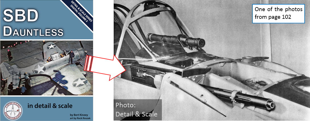
Take for example such a caption that you can find on page 102, below the picture of the forward firing guns (as in figure above):

All versions of the Dauntless had two fixed, forward-firing, .50-caliber machine guns which were fired by the pilot. This photograph was taken from the Pilot’s Manual for the SBD-2, and it shows both of the two fixed guns in place. However, the manual also states that the left side gun was usually removed from the SBD-2 in order to save weight. This was done only on the SBD-2 and usually only during peacetime. Once the war started, the additional firepower of the second gun was more important than the weight advantage gained from deleting one of these guns.

It is a great clarification that cites a reliable source: the original manual. In the other books on this subject you can find various, often contradictory versions about the SBD-1 and SBD-2 forward guns. For example:

Pilots’ armament [of the SBD-2] was increased from one to two .50 caliber guns (Barret Tillman, “The Dauntless Dive Bomber of World War Two”, Naval Institute Press, 2006, page 8);

This statement implies that the SBD-1 had a single 0.50 gun! (And it does not tell us about the source of this revelation).

Another one:

To retain the center of gravity (CoG) position [in the SBD-2], one of the forward-firing machine guns was removed (Robert Pęczkowski, “Douglas SBD Dauntless”, Mushroom Model Publications 2007, page 8);

This statement implies that all SBD-2 had a single 0.50 gun because of the design reasons (aircraft balance). This is also an information without specified source.

You can find in the Web many other descriptions of the SBD-1 and SBD-2. I remember that I encountered somewhere yet another variation of this story. It stated that the pilot in the SBD-1 had two smaller, 0.30-caliber guns.

I am really happy that Bert gives us the ultimate answer on this issue. (In another place in his book he mentions that for this writing he used the six original manuals, one for every Dauntless version. That’s why I take for granted his statement that all SBDs had two 0.50 forward guns).

In the chapter about wings (page 85) I found the confirmation of my hypothesis about the overlapped flap edges:


Posted Image

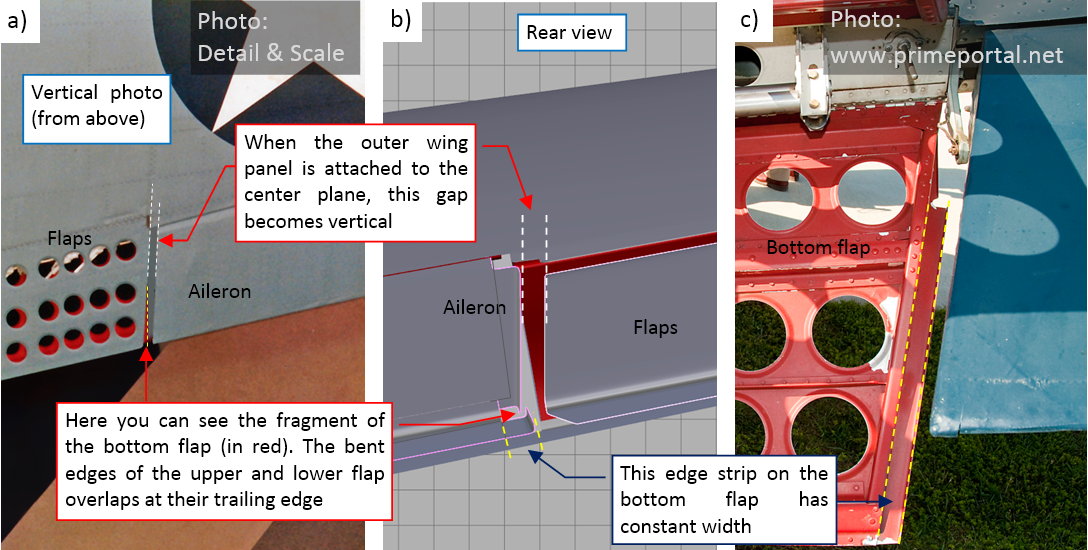
Compare figure above with the second-last picture from my post from previous week. This was a result of the deduction, because when I wrote it, I had no such a vertical photo of the wing with closed flaps.

However, when I studied the photos of the cockpit canopy, I noticed a difference in the shape of the rear segments:

Posted Image

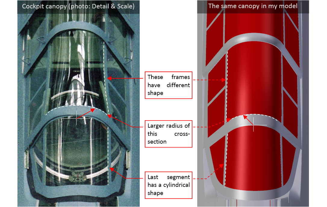
Figure "a", above, shows a fragment of the photo, taken from above. It reveals that the upper part of the last segment had a cylindrical surface, and the radius of the cross section between the third and the last canopy segment was larger than in my model (shown in figure "b", above).

It was further confirmed by all other photos: the side edges of all cockpit canopy segments were parallel, while in my model they are not:

Posted Image

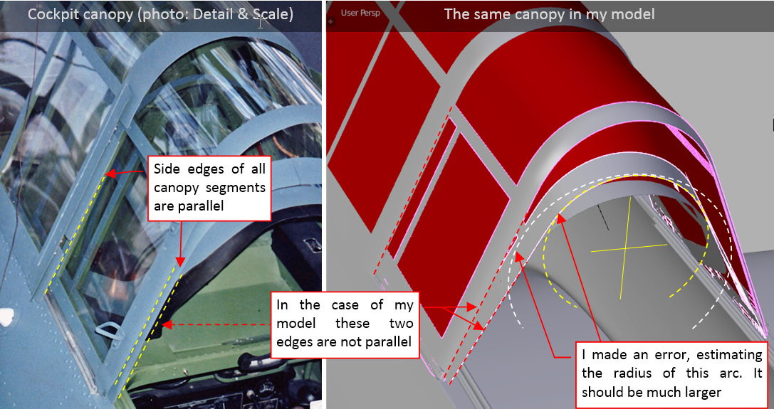
I had to be blind that I did not noticed this mistake before! In fact, it happens when you stick too much to your assumptions about particular shape. In such a state of mind you can see only the details that confirm your hypothesis, and neglecting the others. I assumed that the top radius of the subsequent canopy segments decreased like in the telescope tube: each segment has smaller radius than the previous one. In the effect I received much smaller radius at the end of the third canopy segment than you can see on the Detail & Scale photo.

As the first approximation of this radius I placed inside the model an auxiliary circle (Figure "a", below):

Posted Image

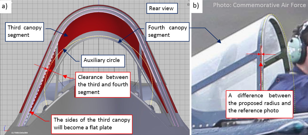
I fitted this circle between the sides of the previous segment and decreased it by an appropriate clearance. Then I checked how it looks in another reference photo (Figure "b", above). In this way I have found that it should be slightly smaller. Thus I started to search for the reason of such a result.

BTW: I used the same reference photo before, to verify the pervious cross section. I determined then that it had much smaller radius than the result presented above. This situation shows that you always have to double check every model element on multiple pictures!

Finally I think that I found the reason: the canopy sides should have a little less steep slope in the rear view. The error comes from the wrong assumption about the shape of the pilot’s canopy:

Posted Image

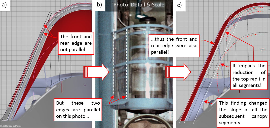
I assumed that the upper horizontal “sticks” of this canopy frame were nearly parallel to the fuselage centerline. In the effect the front and the rear edges of this segment were not parallel (figure "a", above). The photo from Detail & Scale book reveals that I was wrong (Figure "b", above). You can see on this shot from above that both horizontal elements of this canopy frame are parallel to the cockpit border edge. Thus I had to rotate a little the rear edge of the pilot’s canopy, making it parallel to the front edge. It forced me to decrease (by scaling) the radius of the arc that closes the upper part of this canopy. In the effect, I will have to decrease the corresponding arcs in all subsequent canopy segments, including the last segment. As I mentioned in one of the previous posts, I tried to avoid such things, but nevertheless I am prepared: the meshes of my model are relatively simple, so such a modification is not a great problem.

If you want to create a precise copy of any complex object, be prepared that from time to time you have to step back and alter the shape of some finished elements. The work on such a model more resembles a “spiral” than the classic “waterfall” process.

Well, I documented these small bur laborious modifications on the pictures below. Generally, in each canopy segment I had to rotate the side faces along their base (see it in the second segment, depicted in Figure "a", below). Then I scaled down (a little) the upper faces of such a mesh, decreasing in this way the cross-section radius of the resulting surface.

Posted Image

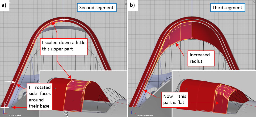
The third segment was more difficult, because the radius of the top arc in its cross sections increases toward the rear (Figure "b", above).

The most difficult part was the last, fourth canopy segment (see the picture below). First I formed its faces in the rotated position (figure "a", below), ensuring that it properly slides into the previous segment, and that its upper part forms a clean cylindrical surface:

Posted Image

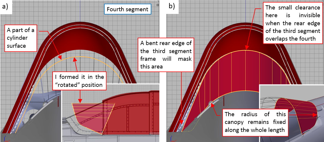
Then I rotated it back into “closed” position, and verified all other details (figure "b", above). Fortunately, it seems that the radius of its rear edge did not significantly change, and it still fits the rear border of the cockpit. (It still looks like in the reference photos). The biggest change occurred in the frontal cross section of this canopy segment.

Indeed, I already altered this radius before: see this post, Figure 57-5. You can see that I made a wrong decision that time, decreasing this section instead of increasing the rear edge of the previous canopy segment. This is a typical “fitting” error, which occurs quite often!

Figure "a", below, shows the modified shape of the cockpit canopy:

Posted Image

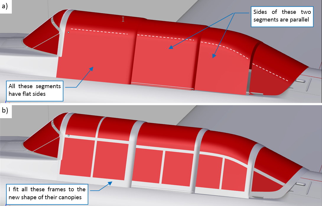
Figure "b", above, shows the same canopy with the updated frames. It is hard to notice any of my changes in this side view, isn’t it? In fact, fitting anew the frame meshes to the altered canopy segments required even more time than the adjusting of the canopy basic shapes! I am really happy that some posts ago I managed to tame the temptation to recreate the internal frames of these canopies. Now I would have much more work with them.

That’s why I am going to recreate all the internal details in the last, fourth phase of this project. In this way I am just creating “time buffer” for eventual new findings, like this one.

Of course I checked the updated canopy on the reference photos. This time I did not want to be blind on eventual differences — as you saw in this post, even slight distance between the model and the photo can indicate a significant error. I slid all the canopy segments into “open” position, to compare them to the CAF photo (this photo has the highest available resolution - see figure "a", below):

Posted Image

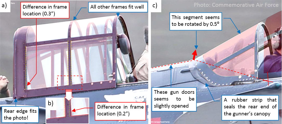
To better see the model on this picture, I assigned a red material to these frame objects. As you can see, most of the canopy frames match the photo. However, there are two exceptions, on the pilot’s cockpit canopy. The bottom ends of the middle and rear frames seem to be shifted (by about 0.2” and 0.3”). It could mean that the slope of these canopy sides had a slightly different angle. However, the front edge and the rear edge of this segment match the photo (figure "a", above). At this moment I will leave this difference unresolved — maybe in the future I will find something, which will help me to explain this difference.

There are also slight differences in the last canopy segment (figure "b", above). However, I think that I can explain them now. This part of the cockpit canopy has two degrees of freedom: you can slide it as well as rotate around its corner. The canopy in figure "b" seems to be rotated by about 0.5⁰. Such a small rotation can be within the tolerance of its lock mechanism. It can be caused by the gun doors, which seem to be slightly opened in this photo. There is also a thick rubber (or leather) strip around the rear edge of this canopy segment. It seals the rear border of the cockpit. (I will recreate it later). I think that the influence of the gun doors and this strip can rotate of this last canopy segment by such a small angle.

In this source *.blend file you can evaluate yourself the current version of the model, described in this post.

This post ends the “modeling” stage of this project. During this phase I formed the general shape of the model, and created all the surfaces which require the classic “image” textures. In the next post I will unwrap these surfaces in the UV space, preparing them for the “painting”. For all other details that I will create during the last, “detailing” phase, I will use procedural textures, which do not require UV-mapping. (The only exception are certain elements of the cockpit interiors, like the instrument panels, but they will have their own, separate texture images).

  • Member since
    June 2014
Posted by Witold Jaworski on Saturday, July 16, 2016 3:50 PM
Because of the holiday break, during July and August I will report my progress every two weeks. I will return to weekly reporting in September.

I have just begun the third stage of this project: “painting” the model. At this moment I am unwrapping its meshes in the UV space. I will deliver you a full post about this process next Sunday. Today I will just signalize how it looks like.

So I started by creating a new reference picture. It had to have a rectangular shape. Inside I placed my drawings of the fuselage, wings, and the tailplane:

The most important thing: all elements of this drawing have exactly the same scale. As you can see, I used flipped left side silhouette in place of the right side view. In fact, I should prepare a 2D drawing of the right side view first, then place it here. On the right side of the Dauntless fuselage, the steps to the gunner’s and pilot’s cockpits were located in different places. There was also a rectangular hatch of the luggage compartment. However, I am a little bit lazy, and I prefer recreating these details directly on the final textures. I will describe what I mean in August, when I report how I drew it.

I use the reference images to keep the proportions between all unwrapped model parts. Sometimes it is also useful for hiding the seams, as in the case of these wings:


I split the mesh into the upper and lower surfaces, and mapped it onto the corresponding parts of the reference drawings. On some textures (for example: the camouflage) it will be impossible to obtain an ideal continuation of the picture mapped along this seam. It is not a problem on the sharp edges, like the wing trailing edge. However, the rounded leading edge is a different case: I prefer to keep it “in one piece”, hiding the texture seam in the first original panel seam on the lower surface of the wing.

When the mesh is mapped on the reference picture, I use another, standard test picture to ensure that the mapped image is not deformed


At this moment I have already unwrapped most of the model:


I still have to unwrap the engine cowling. When I finish it, I will publish a full post about this process, as well as the updated model. (I will do it on next Sunday — July 24th).

In this guide you can find detailed step-by-step instructions how to map various aircraft model meshes onto texture images, as well as all other details of “painting” the digital models.
  • Member since
    June 2014
Posted by Witold Jaworski on Monday, July 25, 2016 6:45 AM

This week I finished mapping all the parts of my model onto a two-dimensional image. Figure below shows the test image, mapped on the model surface. (Its pattern helps me in keeping the same mapping “scale” for each object):

Posted Image

I did not “unwrap” the small details, like the parts of the propeller mechanism, because I will “paint” all the small parts using procedural textures.

Figure "a", below, shows how these meshes are distributed on the 2D UV map (you can see the reference image beneath). At this moment I mapped just a single (left) wing, the symmetric halves of the rudder and the fin, as well as the left side of the fuselage. The upper and lower part of the tailplane are symmetric, so I just mapped its left, upper side. I will create the other sides and symmetric elements later, at this moment I just reserved the necessary UV space for these objects.

Posted Image
In figure "b", above, you can see that the reference image looks like the first approximation of the skin details. In the next post I will draw an image of these details that fits these unwrapped meshes. It will be the base for all the textures I will create for this model.

In the rest of this post I will shortly describe my typical approach to UV mapping.

This post is not intended as a detailed step-by step guide. If you want such an introduction “for the absolute beginners”, use this book. It is accompanied by many useful Blender add-ons, for example an add-on that exports all the unwrapped objects into such an SVG image, as shown in figure "a", above. (In the standard Blender you have to export each object separately).

Let’s analyze the wing case. I am going to map its upper and lower surface separately. Thus I defined two auxiliary vertex groups, to easily select these mesh parts:

Posted Image

I use the Project From View command to create initial mapping. For the upper wing surface I use the projection from the local top view of the wing object:

Posted Image

I shifted and scaled this shape, fitting it to the reference image. I used “pinned” vertices from the flat part of the wing surface to this image (using the Pin command). Then I invoked (in the UV/Image Editor window) the Unwrap command:

Posted Image
It “relaxes” (unwraps) all the faces that are not pinned. In this case Blender unwrapped the leading edge and wing tip edge.

I unwrapped the wing bottom surface I the same way. At this moment the seam line between the upper and lower wing surface lies in the middle of the leading edge (figure "a", below). While it is OK for the relatively sharp edge around the wing tip, the minimal discontinuity of the texture image on the most exposed, forward part of the wing would spoil this model. Thus I usually hide such a seam, leading it along the nearest panel seam line on the lower wing surface (figure "b", below):

Posted Image
When I marked the seam line, I called another Unwrap command. In response, Blender “teared” the bottom part of the leading edge from the lower wing surface, and “glued” it to the upper surface:

Posted Image
As the final touch, I straightened the rib edges (it is much easier to draw the texture images on such an “orthogonal” wing layout). The only exception is the skewed inner edge of this wing segment:

Posted Image
When the wing surface was mapped, I replaced the reference image with the standard Blender test image (UV Grid). It is prepared for finding eventual mapping distortions:

Posted Image

As you can see, there was a serious distortion along the leading edge seam.

The remedy for such a flaw depends on the mesh local conditions. When it occurs on a flat surface, you can make the seam line sharp (setting its Crease coefficient to 1.0). However, in this case it would spoil the cross-section of the leading edge. The other, less preferable solution is to insert an additional, perpendicular edge loop. When you locate it in the proper place, it efficiently removes such a distortion:

Posted Image

(I do not like creating such additional edge loops, because each of them makes the resulting mesh topology more complex. However, sometimes you have no choice, as in this case).

In this source *.blend file you can evaluate yourself the current version of the model (as in the first illustration from this post).

  • Member since
    June 2014
Posted by Witold Jaworski on Saturday, September 10, 2016 2:03 PM

After a long break in August and September (I had to finish a demanding project in my daily work) I am back. This week I made a “slow start”: because in my last July post I finished mapping the SBD-3, now I mapped in the UV space parts that are specific to the alternate Dauntless versions: SBD-1 and SBD-5.

Let’s start with the SBD-1: when you switch into its scene, you can immediately see the gray elements that are not mapped in the UV space (as in figure "a", below). These parts are specific for this version:

0062-01.jpg


It did not require a lot of work *– just to unwrap few additional meshes in the UV space. You can see them in figure "c", above). I placed their faces in the same location, as their counterparts from the SBD-3. In figure "b", above, you can see the SBD-1 model after this update.

Then I had to make similar work in the SBD-5 scene. The engine cowling of this model contains more differences, thus it required much more work:

0062-02.jpg


When all the meshes in all SBD models were unwrapped, I had to export them into a 2D drawing. (I will need such a picture as a reference for painting various textures). I prefer to keep it as a scalable vector drawing, thus exported it into an SVG picture, which I can edit in Inkscape:

0062-03.jpg


The standard Blender command allows you to export only the single mesh of the active object. Some years ago I wrote an add-on which exports into SVG all selected objects at once. (You can find this add-on and learn how to use it in the III volume of this guide). It is extremely useful for such a model built from multiple objects, like this one.

Inside Inkscape I placed the exported objects onto a layer that has the same name as the defualt UV map in Blender: UVMap. (In the next posts I will prepare in Blender some other alternate UV maps, thus this naming convention is important).

Internally, I split in Inkscape the contents of the UVMap into five sublayers:


0062-04.jpg


Two bottom layers (Color, Common) contains the elements that are common to all three models. I created Color layer for the future use. It contains just the fixed parts of the wing. I am going to use a separate texture for the national insignia and various technical labels. On some SBDs the stars on the wing lower surfaces were so large that they will require the seam line directly on the leading edge. Thus for this purpose I am going to create an alternate UV map for the wings. I will place it in Inkscape on additional Decals sublayer. Then, to create the UV layout for the insignia texture, I will hide the Color layer. When I will need the UV layout for the camouflage texture, I will turn off the Decals layer, and make the Color layer visible.

Why I did not simplify this drawing, creating in Inkscape a separate layer for each texture that would contain all the required objects? Because in such a case I would have to duplicate all of the common objects – sometimes several times.

The progress of my modelling project is not like a “waterfall”, it more like a spiral. From time to time I have to return to a finished stage, and fix something there. That’s why I always try to have just “one string that controls all”: in this case it means having single instance of every mesh in the Inkscape drawing. When I have to modify something in the corresponding Blender mesh, I will need to update just single element in this drawing, instead of multiple instances in the “simpler” version.

I use the same method as described above for obtaining the UV layout for a particular Dauntless version. There are three sublayers, named: SBD-1, SBD-3, and SBD-5. In each of them I placed just the elements that are specific for these version. For example, the figure below presents contents of the SBD-3 layer:

0062-05.jpg


When you combine it with the basic layers (Color, Common), you will get the complete UV layout for the SBD-3:

0062-06.jpg


(Of course, at this moment this layout contains only the left side of the model. I will update it later, adding the elements from the right side).

In this source *.blend file you can evaluate yourself the current version of the model, and here is the Inkscape file.

JOIN OUR COMMUNITY!

Our community is FREE to join. To participate you must either login or register for an account.

SEARCH FORUMS
FREE NEWSLETTER
By signing up you may also receive reader surveys and occasional special offers. We do not sell, rent or trade our email lists. View our Privacy Policy.