SEARCH FINESCALE.COM

Enter keywords or a search phrase below:

SBD Dauntless

73382 views
196 replies
1 rating 2 rating 3 rating 4 rating 5 rating
  • Member since
    June 2014
Posted by Witold Jaworski on Tuesday, June 2, 2020 1:39 PM

In this posts I will analyze differences between my 3D model (built from 2015 to 2019, as reported in this thread) and the SBD geometry data obtained from the original documentation. Actually, I can perform such a ultimate comparison for the wing, because I found its original geometry diagram in the NASM microfilm. In previous post I used it for preparing a “reference frame” for such a verification. Results of this comparison will allow me to determine the real error range of my previous methods described in this blog, in particular – the photo-matching method.

Unfortunately, the incomplete microfilm set from NASM does not contain any other geometry diagram, so I will not be able to prepare such a precise reference frame for the SBD fuselage or empennage.

At the beginning, I identified an error in the wing location. It was determined by the position of leading edge tip of STA 66, marked as point A in the picture below:


In this post from 2015 I determined this location using the general arrangement diagram that I found in the SBD maintenance manual. As you can see above, there were issues in deciphering some of its dimensions. One of them was the distance from the thrust line to point A. I identified it as 20.38”, which means that in my model this distance from the fuselage ref line is 26.38” (6” + 20.38”).

A high-resolution scan of another arrangement diagram from Douglas microfilm (dwg no. 5120284) shows that this distance was 26.52”. (You can see this dimension in the picture above). Thus – this is the first identified error in my model, caused by a mistake in reading available drawings: 0.12”.

After re-adjusting wing position in my model, let’s examine the center wing section:


In previous post I already mentioned my wrong assumption about the 15% thickness of the outer wing section at STA 66 (i.e. at the section joints – see Figure 109-4 in that post). Now I can see the effects of this error: upper wing surface of my model is located about 0.35” above the red reference rib (i.e. above the rib created according the master diagram ordinals). As you can see, I also made minor mistakes in the leading edge shape. There is an offset of 0.15” in the top view contour, and a difference in the shape of the forward part of the wing root profile. The latter does not exceed 0.3”. Because of these differences, you can see that the original wheel bay protrudes a little from the wing leading edge of my model. In general, wing webs (spars) locations are quite precise – just the Web #2 is shifted by 0.3”.

Let’s look now at the bottom side of this wing section. Surprisingly, the Web #5 location and the radius of the trailing edge precisely match the master diagram data. However, the lower wing surface is placed 0.05” above the wing ordinates (this is a minimal difference, but still visible in this model):


I also properly identified location of the Web #1. In my model I placed the most forward (“nose”) web in a slightly different location – about 0.15” to the rear. I made the biggest error in the shape of the lower, forward part of the wing root profile: it reaches about 0.5” near the leading edge. (As I remember, I assumed this airfoil shape basing partially on fitting the main wheel, and partially on the photos). The wheel bay location and size are surprisingly close to the master diagram data: the overall error does not exceed 0.15”.

In general, the center wing section of my model matches quite well the master diagram ordinals. Of course, I will fix all these differences, but I will do it later (I describe it in another post).

Now - what about the shape of the outer wing section? I found there much greater differences:


While the aileron and flap seem to match the master diagram pretty well, there is a significant difference at the wing tip. Also, the fixed slats are shifted outward by about 1”. However, we are comparing here my original wing model (dihedral angle along trailing edge: 10.2°) with the master diagram drawing placed on the original reference plane (dihedral angle: 8.5°). In Figure 109-15 from previous post I demonstrated that the real wing tip was 1.43” closer to the aircraft center plane than the tip depicted in this reference image. (This is because of the strange location of the reference plane in the outward wing). To fully assess these differences, I switched the current view to the projection aligned to the original, oblique reference plane of the outward wing:


Here we can see that the wingtip of my model exceeds the master diagram shape by 2”! On the other side, this is the result of two coupled errors. As you can see in this post and this post, I used the arrangement diagram from SBD maintenance manual as the primary source of the basic geometry.

In this diagram the basic trapezoid of the outer wing is described by five dimensions. I could not know that three of them are wrong! In the picture below I placed these dimensions in blue and red boxes (the wrong values are in red boxes):


In practice, this means that I unconsciously “stretched” the outer wing in my model, matching the wrong wing span. (For example – I shifted entire outboard wing section outside STA 66 by 0.8”. Such a modification did not agree with the stations diagram from the maintenance manual, but it was the only way to place the wing tip according the dimension from this arrangement drawing).

By the way: now I can see another error in the drawing above. Note the partial span dimensions, which I marked as L1 (66) and L2 (183.05). As you can see, their sum should give the L dimension (249.187). Does it? Certainly not! (66+183.05 = 249.05). While L1 is the location of STA 66, confirmed by many reference dimensions on various blueprints, L2 value fits to nothing. This could be the span of the outboard wing measured along the reference plane (185.05 – the third digit in the picture above can be both: 3 or 5). If this assumption is true, such a dimension should never appear in this top view, in particular in this closed dimension chain.
 
As I mentioned in at the beginning of this post, in this comparison I would like to determine the error range of my photo-matching method. It bases on the relative comparison: to determine absolute dimensions of the analyzed object, you previously must know at least one or two of its original dimensions. As you can suppose, I treated the wrong basic trapezoid of the outer wing from the arrangement diagram as the confirmed contour, and appropriately arranged the reference photos. You can see the results in this post about verification of the wing shape.

To estimate the error range related to the photo-matching method alone, I compensated the effect of the assumption errors (improper wing span) by adjusting my model dimensions. I scaled spanwise the outboard wing, decreasing its size by about 1%. After this update, the basic wing trapezoid of my model fits the real “reference frame”. Below you can see the result of a new comparison:


There is still difference in the wingtip contour, but now it does not exceed 1”. What’s more – now the wing slats match the blueprint quite well (the error does not exceed 0.12”). There is still a difference of 0.8” in the location of the gap between the flap and the aileron. However, I placed this gap in my model according the stations diagram from the maintenance manual, so it is shifted now. (I remember that I always noticed small difference in location of this gap when I matched my model to the photos).

You can see the originally matched photos in this post about wing shape verification. In particular, look there at Figure 31-8 and my description below that picture – it looks that initially I made a proper assumption about the contour arc, just its radius was somewhat different! A few months later I made another verification, described in this post (in particular, see Figure 42-8). Now I think that some problems with matching the wing tips of my model and the photo (as in Figure 42-9 in that post) were caused not by the dynamic wing deformation, but by assuming wrong basic dimensions.

CONCLUSION: it seems that despite the few available photos of the wing the errors of my photo-matching method did not exceed 1” (0.4%) in this SBD model. I think that this is an acceptable result, especially in the cases of aircraft which original blueprints are not available.
 
(Last year I wrote a detailed two-part tutorial on the photo-matching method: here you will find its part 1/2 and part 2/2).

However, in my SBD model these photo-matching errors coupled with other errors, caused by assuming wrong overall wing dimensions. I read them from the only available documentation, which I had in that time: the general arrangement drawing from the SBD maintenance manual. I think that such a situation is a special case. I will still trust the dimensions from manufacturer’s blueprints. This is the ultimate source, and – despite issues like the one described in this post – they build the real aircraft using these drawings! Of course, if you find two different blueprints of the same assembly, it is a good idea to compare a couple of their key dimensions. Just in case.
  • Member since
    January 2015
Posted by PFJN on Tuesday, June 2, 2020 6:08 PM

Hi, 

The levels of detail that you have been able to pull together is amazing.

Pat

1st Group BuildSP

  • Member since
    June 2014
Posted by Witold Jaworski on Monday, June 15, 2020 11:33 AM

Pat, thank you for following!

Today a short post about another wrong dimension, then in the further posts I will describe my work on the fuselage "reference frame".

______________________________________________________

In some aircraft it is difficult to provide the precise value of overall length. One of them is the SBD Dauntless, because of its easily demountable spinner used in the first three variants (SBD-1…-3). Also the length of the Hamilton Standard Hydromatic spinner hub, used in the later SBD variants, can vary – especially in the restored aircraft. Thus, for verification of model kits or similar purposes I would suggest checking the distance between two easily distinguishable points: from the firewall to the tip of the tail cone. This dimension remains the same in all SBD variants. Preparing the fuselage blueprints for my model, I could determine this distance using the tail cone assembly drawing:


The key information is provided by the stations marked in this drawing: their names describe distances from the firewall. (You can read them yourself from the high-resolution version of this drawing). I could read that the fuselage tip cone starts at station 271.6875 (11/16) and ends after station 308. However, this drawing does not provide the closing dimension (from station 308 to the tip), thus I had to measure this distance. Assuming a quite wide tolerance (1%), I estimated it as 6.7”. This means that the distance from the firewall to this fuselage tip was about 114.7” (+/- 0.05”). The light bulb protruding from the tip is not documented in this drawing. From the photos I could estimate its length as 1”. However, the information provided in this blueprint forced me to follow the “Douglas convention” of skipping the light bulbs dimensions. I already noticed this convention in the case of the SBD wing span: it was distance between the bases of the running lights, located on the opposite wing tips.

Later I discovered that I could verify this estimated distance using certain dimensions from the general arrangement drawing (dwg no 5120284):


I marked these three partial dimensions in the figure above. I subtracted from the total length (399.25”) the distance from the spinner tip to the wing leading edge (at STA 66: 91.56”), then added the distance from this point to the firewall (9”). I was surprised when I obtained a quite different result: 316.69”. This is 2” more than I measured in the previous blueprint – I could not explain such a significant difference!

However, looking at this arrangement drawing, I found another dimensioning chain:


First two dimensions (9” + 274.812”) describe position of the rudder hinge axis, while the third dimension describes distance from this axis to the rudder tip (29.875”). (This rudder chord length is confirmed by corresponding dimension in its assembly drawing no 5156459). Obtained result: 313.688” is 1” short of my measurement, but it does not include the small part of the fuselage tip behind the rudder:


Fortunately, another source confirmed this result: the arrangement diagram from the SBD-6 maintenance manual:


Although the aircraft total length here is slightly different from dwg 5120284 (33’ 0.1” vs 33’ 0.25”), all three dimensions related to the rudder size and location are identical. (Just their fractional parts are expressed using decimals). This arrangement drawing is more detailed: at the tail tip you can see 1” dimension related to the remaining distance from the rudder tip to the running light base. Thus, the distance from the firewall to the running light base at the tail tip (314.687”) agrees with my initial measurement (314.7”).

Comparing these two versions of the arrangement diagram I found some other simplifications in dwg 5120284. It seems that it was drawn by a draftsman who skipped many detailed dimensions, and truncated the less important fractional parts from the remaining ones:


Fortunately, the main dimensions like the overall span of the stabilizer are identical in both drawings.

Frankly speaking, after finding these errors I decided that I cannot trust dimensions from drawing 5120284, if they are not confirmed in other blueprints. This conclusion seems to be quite paranoid, but it looks that somebody in Douglas accepted this blueprint without proper verification.

Ultimately, for the SBD scale plans and model kits I propose following length checks:


Both distances are identical in all Dauntless versions.

I do not suggest checking the overall wing span, because the value used in all general drawings (including the manufacturer arrangement diagram): 41’ 6.37” is wrong due to conceptual mistake. (I described this error at the end of in this post). The real SBD wing span was 41’ 3.2”, but I doubt that any drawing/model kit fits this dimension. Thus I suggest measurement of two other spans, which are confirmed in all assembly blueprints:


I suppose that you can trust more the model kit/scale plan that fits these four dimensions. The other distances can vary, due to wrong wing span, provided by Douglas itself, or the wrong fuselage length specified in the BuAer SBD-1, SBD-2 and SBD-3/-4 performance reports. (These lengths were repeated in all publications about his aircraft. In the result – for the SBD-3 both: the length and the span were wrong in all sources that I saw. See this and this post for more details).

  • Member since
    June 2014
Posted by Witold Jaworski on Thursday, July 16, 2020 11:27 AM

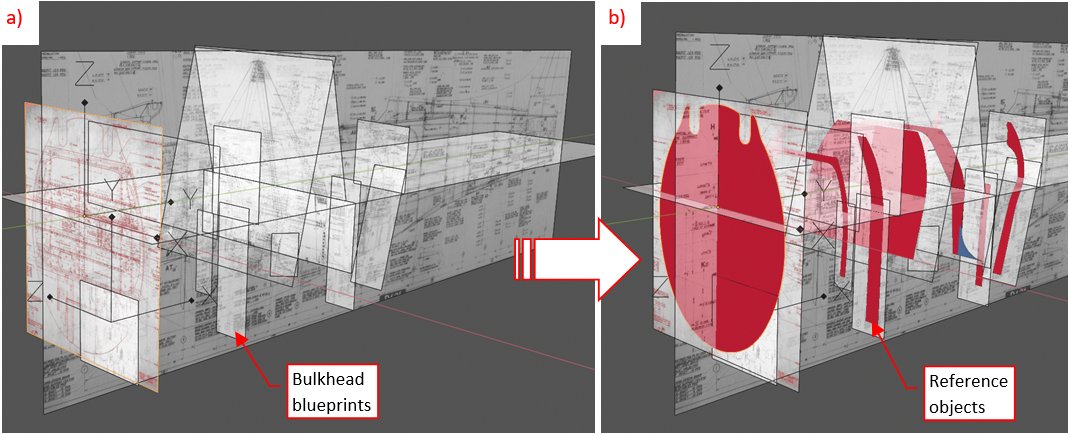
As I already mentioned in this post, my microfilm set does not contain the fuselage geometry diagram. (I suppose that it was included in the missing roll C). Thus, this part of my work will be much more difficult, because I even do not have complete set of the bulkhead drawings! Just found a structure assembly drawing (i.e. side and vertical views), skin panels assembly drawing, mid-fuselage bulkheads, and some bulkheads of the tail. In the picture below I marked these undocumented areas of the fuselage in transparent red:


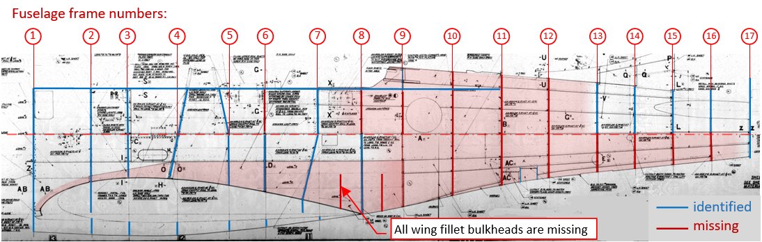
Douglas blueprints refer to the fuselage bulkheads as “frames”. They are numbered from 1 (the firewall) to 17 (the mounting base for the tail wheel and horizontal stabilizer). Of course, the fuselage assembly drawings provide their positions, measured from the firewall. (You can find them in this assembly drawing of the skin panels). In this post I will refer to fuselage bulkheads using their ordinal numbers, shown in the picture above (for example: “frame #05”).

However, even the identified blueprints of the fuselage frames are usually assembly drawings, which means that they do not contain any useful dimensions (as the frame #05 in figure "a", below):


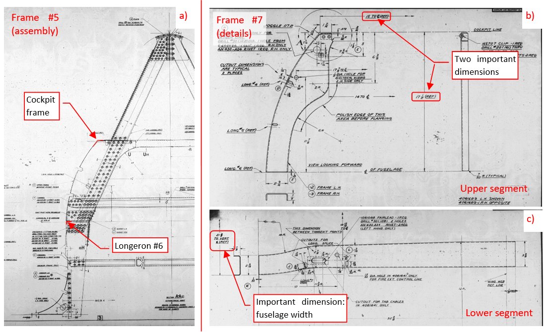
All you can do witch such a drawing is to use it as a reference image. This is not the best option, because these microfilm pictures are always slightly deformed, due to paper folds and distortion of the camera lens. In the case of detail drawings you can find some useful dimensions, like the overall fuselage width (measured from the center plane), or the height. (As in drawings of frame #07 in figures "b", "c", above). Note that these frames are split along the fuselage reference plane into the upper and lower part. While the upper part (figure "b", above) at least resembles a bulkhead, in the case of the lower part (figure "c", above) I had to think for a while before determining its inner and outer side.

Because I have only a few vertical photos of the fuselage, one of the most important information are bulkhead widths. I have collected them just for the 7 frames:


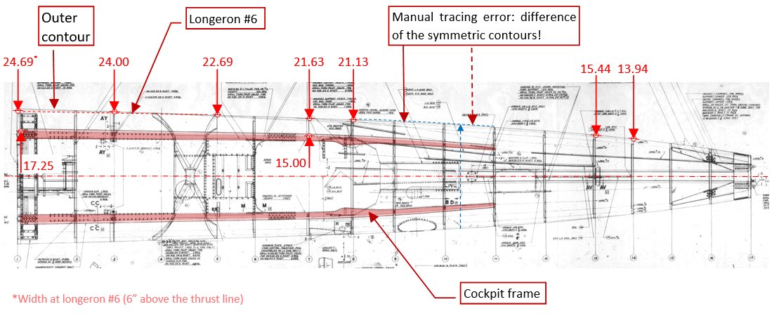
Except frame #03, these fuselage width are measured at the reference plane (longeron #06). In the case of the firewall, this is not the point of the maximum width. (Firewall has an elliptic shape, which origin lies 6” lower, on the propeller thrust line – see figure below). Note that I also found two widths of the cockpit frame. These two points, combined with the height from figure "b", above, allowed me to determine precise location of this very important longeron. (It forms a base for many other dimensions). Unfortunately, I did not find explicit width dimension for the last frame (#17).

I also verified the top view of the fuselage (the third illustration in this post), checking its symmetry. Unfortunately, I found that this contour is asymmetric (i.e. the drawing is deformed) in the area without dimensions (between frames #8 and #11). This deformation could occur during microfilm production. (This blueprint was originally split between four film frames, and frame 3 and 4 overlap in this area). However, these drawings were manually traced in ink, and this can also be a human (draftsman) error.

If you wonder about the error range of the lines traced on the original blueprints, look at the picture below. It shows two drawings of the firewall. One of them is in red, while the other in black:


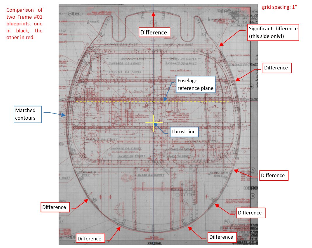
As you can see, contours of these two firewall “instances” can vary even by 0.3” (0.4% of the overall size). Which one is closer to the real contour? I decided that I will use the red drawing, because it is symmetric, and its contour mostly agrees with the left side of the black blueprint. I suppose that at least part of these differences are non-critical draughtsman errors.

The most important elements of the technical drawings are their explicit dimensions. Depicted object has just to resemble the real thing, making the drawing readable. All curves are described by datapoints (ordinals), grouped in the geometry diagrams. That’s why for a manufacturer/workshop both of the compared firewall assembly drawings are valid, in spite of these differences.

Unfortunately, without the fuselage geometry diagram I have to rely on these “not-so-precise” object contours. This means that in my “3D reference frame” that I am building in Blender the possible error range will be much wider in the fuselage than in the wing. (Because the wing reference objects were mostly based on the original geometry diagram). In the second part of this post I will try to improve this situation a little, checking some doubtful/undocumented areas with the reference photos.

I placed the identified drawings of the fuselage frames in the 3D space, using some of their largest horizontal and vertical dimensions for determining the proper scaling. However, in the effect there were so many overlapping half-transparent pictures (as in figure "a", below) that in the practice the whole thing could not be used as a reference. It forced me to recreate each frame as a 3D planar contour, and hide their source drawings:


For the beginning, I focused on the better documented mid-fuselage. Once the bulkheads were created, I connected them with the cockpit frame and other longerons:


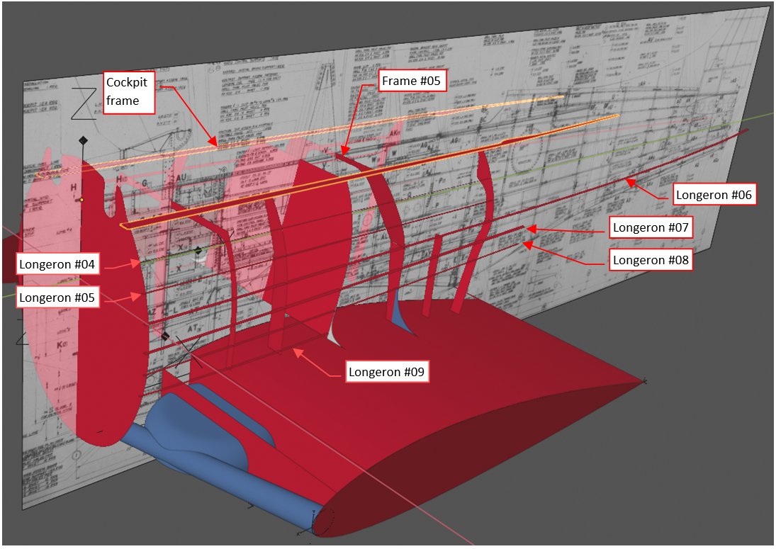
The longest longeron #06 lies on the fuselage reference plane, thus its shape from frame #05 to frame #17 determines the fuselage contour in the top view. For the convenience, these longerons run along the original longeron lines, depicted in the fuselage assembly drawing.

These longerons helped me to find and fix minor differences in the shape between subsequent bulkheads:


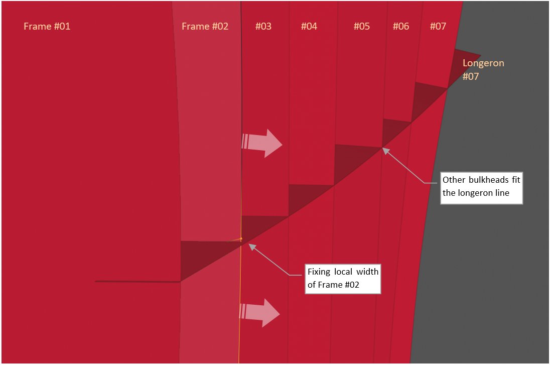
(When you look along the longeron at high angle, as in the picture above, you can quickly find all differences in the local width of the subsequent bulkheads.)

That was the easier part. Now I have to recreate the tail bulkheads. As you can see in the first illustration in this post, I found only the upper parts of frames #13..#16, and complete closing frame (#17). They contain just a few usable dimensions. Paraphrasing well-known Goya’s title, “the lack of dimensions produces assumptions”, and assumptions are the main source of eventual errors. However, there is no other way. In this case I have to make several assumptions about the shape of tail bulkheads.

Of course, first I reviewed all the blueprints for any hint about their shape. I have found some fragmented contours of tail bulkheads placed as additional information in other drawings. For example – figure below shows all what I found about frame #09:


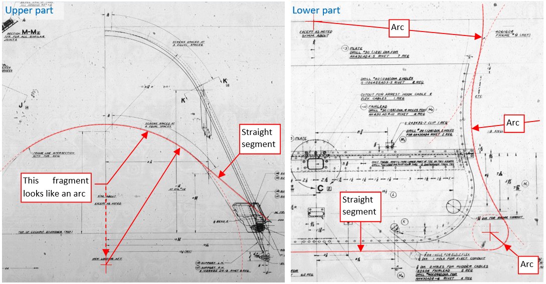
The continuous red line marks the frame #09 contour, identified in two drawings. The left picture comes from cockpit enclosure assembly drawing, while the right picture is a fragment of an internal diaphragm assembly. The drawing of the cockpit enclosure (left) contains upper part of frame #09 contour. It looks as it was formed from an arc and straight segments (this is my first assumption). In the diaphragm assembly (right) you can see a complete frame #09 contour, up to the reference plane. It seems to be formed by a 3 arcs and a straight segment (this is my another assumption).

Design of this fuselage tail comes from the historical Northrop Gamma/A-17 aircraft line. First Gamma was built in 1932. In that time aircraft designers seldom incorporated advanced curves in their shapes, because they were much more difficult to recreate in the workshop than ordinary arcs. That’s why I stick to identifying circular sections in these contours.

I placed these two images in the 3D space, then created auxiliary circles fitting the assumed arcs. Using their contours, I created the model of frame #09:


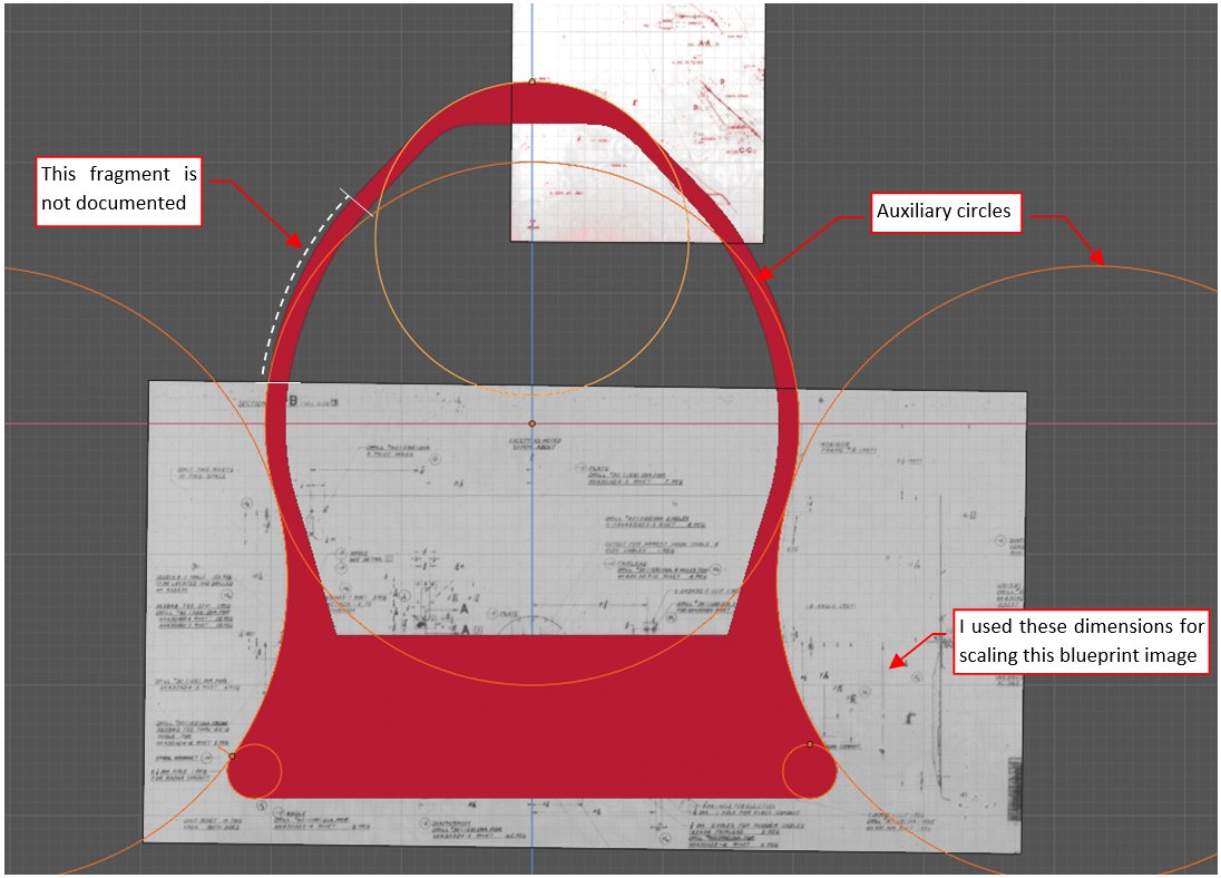
As you can see, there is still a completely undocumented segment above the fuselage reference line. I based its shape on the corresponding segment in the last documented frame (#07).

I could identify similar arcs in the tail bulkheads. They fitted the available drawings of frame #13, #14, and #15. To ensure smooth shape transition between subsequent bulkhead contours, I organized these auxiliary circles into “cones”. Below you can see pictures of the first two cones, which form the main part of the tail:


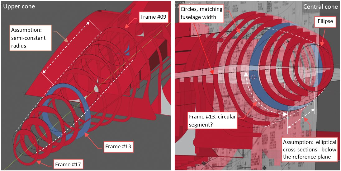
For easier recognition, I marked the first documented tail frame (#13) in blue. Its width and height are determined by explicit dimensions, while the shape of previous frames is based mainly on assumptions. In picture above, left, you can see the upper cone. It starts with the frame #09 contour, which should fit the cockpit enclosure (arc diameter: 22.5”). Then it remains nearly constant up to the frame #13. (In fact, it seems to slightly enlarge its diameter, reaching maximum – 24” – at frame #13, then quickly decreasing in the further frames. For frames #16 and #17 this contour is meaningless, because their upper parts are completely hidden inside the horizontal stabilizer fairing).

In the picture above, right, you can see the central cone. Its axis lies on the fuselage reference axis, and its side contour is the side contour of the fuselage. I did not find any drawings of the lower part of frame #13. Basing on the side and top fuselage contours I decided that it was a simple circular segment, precisely matching the central cone. I assumed that the lower contours of all further frames (#14, #15, #16, and #17) were elliptical, because frame #17 seems to fit into an ellipse (as you can see in figure "a", below):


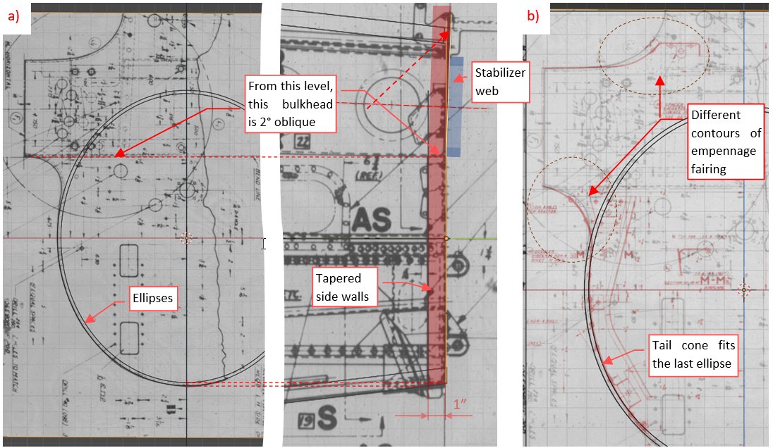
This frame had relatively large, tapered side walls (1” wide), thus I placed in this drawing two ellipses: one for the inner, and one for outer contour (both marked in the source blueprint). As you can see, these contours fit them pretty well. Note also that the upper part of this bulkhead is 2° oblique, to fit the attached rear stabilizer spar (web).

I also verified this elliptical contour in another drawing, of the first bulkhead in removable tail cone section (you can see it in Figure "b", above, marked in red). The last ellipse fits both blueprints. However, I noted differences between these drawings in the empennage fillet shape. (Compare its black and red contours in the marked areas of Figure "b", above).

In the next post I will continue my work over the lower part of the fuselage. I still have to prepare references for the large wing fillet, which spanned along half of the SBD fuselage length.

  • Member since
    June 2014
Posted by Witold Jaworski on Tuesday, August 18, 2020 11:40 AM

In previous post I started creating 3D reference objects for the SBD fuselage. In this post I will complete this work. I will focus here on the difficult part: the wing fillet. It spanned along more than half of the SBD fuselage length. In this post I am going to prepare reference geometry that describe its shape from bulkhead #4 to bulkhead #13. Unfortunately, in drawings from the NASM microfilms I found just a few contours related to this feature:

Just in case: the illustration above uses the fuselage bulkhead (frame) ordinal numbers, introduced in the previous post. I am referring them using these ids (for example: “frame #05”). See figure below for their map.

Figure "a" above shows horizontal contour of this fillet, which I found in the panels assembly diagram (dwg 5063493 – see its high-resolution version). Figure "b" above shows two contours of the forward wing fillet segment (the part placed over the wing). I found the contour of frame#08 (marked in red) in a carbon dioxide installation assembly drawing. Figure "c" above shows four contours of the rear part of the wing fillet (the part behind the wing trailing edge). In previous post you can find description the source drawing that I used for recreating frame #09 contour. Contours of frame #10 and #11 are copied from battery and tool compartment drawings, while frame #12 (and #11) – from flares assembly drawings. As you can see, all these contours were placed in their original blueprints just as additional information, thus I do not expect that they precisely depict the real lines.


It seems that the geometry of this wing fillet can be described as a fragment of two bent cones, shown below:


The forward cone is adjacent to the wing and fuselage. Rear cone starts at wing trailing edge, and extends up to frame #13. (At frame #13 it finally joins the central cone of this tail, described in previous post). I identified circular cross sections of wing fillet cones using drawings shown in the previous figures "b" and "c". These two cones must be adjacent. To see better what I mean, look at figure "a", below:


I built instances of these fillet cones (shown in Figure "a", above) around circles shown in the previous figure. Note their adjacent area between frame #09 and #10 (ideally it should be just a single adjacent edge).

I shaped the horizontal contour of the rear cone (precisely: its topmost segment, between frame #08 and #09) according the fuselage panels diagram (as in figure "b", above). The side contour of this cone simultaneously fits the bottom contour of the fuselage. Then I noticed a serious flaw in this drawing: its wing fillet contour between frame #09 and #10 it does not fit the actual contour of the rear cone (see Figure "b", above). What’s more, this blueprint does not show any wing fillet contour behind frame #10.

To better show in the 3D space what this difference means, see Figure "a", below:


The contour from fuselage panels diagram suggests that the bottom part of frame #10 was as wide as the upper part. To illustrate this difference, I shifted in Figure "a", above, the circular cross section of the rear fillet (black circle) into corresponding location. Because in this blueprint the contour line “sinks” into the fuselage contour at frame #10, one can only speculate about eventual position of the next cone section, at frame #11. Anyway, the photo of the frame #10 from a restored aircraft (Figure "b", above) confirms the current shape of this bulkhead (highlighted in the picture above). This means that the contour from the fuselage panels diagram is wrong, at least for the part that spans behind frame #10. If so, what about the remaining part, between frames #08 and #09?

I decided to check this issue on the reference photos, that I matched using the previous version of my SBD model. Surprisingly, the PAM photo of the original SBD-5 (before restoration) fits ideally the reference frame (Figure "a", below):


Figure "b" above shows enlarged fragment of this photo. As you can see, the shape of the real wing fillet contour is completely different from the shape copied from the fuselage panels diagram! The only common point lies at frame #09. The remaining contour of the rear fillet cone (marked by white dashed line) seems to be a perfect continuation of this real curve.

How to explain such an error? In technical drawings, the most important thing are the explicit dimensions or references. (In the case of this panels diagram these are references to skin thickness and riveting seam types). Depicted object has just to resemble the real thing, making the drawing readable. All eventual curves are described by data points (ordinals), grouped in the geometry diagrams. That’s why for a manufacturer/workshop this panel assembly is valid, in spite of these wrong lines. I suppose that it would be less readable with the real fillet contour drawn after frame #09

I modified the shape of the rear cone between frame #08 and #09 according this reference photo. To fit it into the fuselage side contour I had to modify shape of the last two sections of the forward cone (Figure "a", below):


I marked the modified area of this cone in purple color. (To make this reference object more convenient, I reduced the forward cone to the most important quarter). As you can see, I flattened a little the outer parts of last two circular sections. Of course, I checked this shape with another reference photo (Figure "b", above). Now it differs a little from the ideal circle depicted in the assembly blueprint of the carbon dioxide system (see area "b" in the first figure in this post), but I assumed that it was a simplified contour, used for the illustration purposes.

The updated, somewhat shorter outer wing segment fits much better the reference photos (this is another confirmation that I read properly its assembly drawings). Now I used these photos for checking the fuselage side contour:


It is interesting that in this way I am comparing the real aircraft with its blueprint (in this case – the side view of the structure assembly). As you can see in the picture above, I found some differences along the upper edge of the tail. Figure below shows their details:


First, look at the fin contours: the real shape is quite different from the blueprint contour! Of course, I also checked this difference in reference photos of other aircraft (the PAM SBD-5). They confirmed these findings. In the picture above you can also see a difference in the fuselage height behind gunner’s cockpit enclosure. However, this one was not confirmed by photos of other aircraft. In the cockpit enclosure drawing I also found the explicit dimension of the fuselage height at the edge of gunner’s cockpit: 26.65”. Thus, I suppose that this is an individual shape variation, specific to the restored machine depicted in this photo. (For example – caused by the modified gun doors).

However, I used information from the reference photos to make an adjustment of the fuselage height, in the front of the fin:


As you can see in the picture above, the upper contour of the fuselage is “anchored” by two explicit height dimensions: at the corner of the gun doors (26.65”) and at frame #13 (18.09”). Except these two heights, I also found among the SBD blueprints a drawing of the flares loading door. Unfortunately, it does not contain any useful height dimensions. However, its side shape fits the reference photos pretty well, while it does not fit the fuselage contour in the basic structure assembly drawing. Ultimately, I decided that the in the reality the top of the fuselage was located somewhat higher in this area than in the structure assembly blueprint. (If the fin contour in this blueprint is wrong, the same could happen to the contour of the upper fuselage). The difference was about 0.3”. I adjusted the fuselage shape according the reference photos and the flares loading door drawing.

After shaping this side contour (it corresponds to longeron #01 in the SBD skeleton) I also recreated the 14 remaining longerons. Their locations match the structure of the real aircraft:


In fact, it was quite slow process: I had to fix minor differences in the bulkhead shapes along each longeron. Sometimes the line of newly added longeron forced me to correct the previous one. The surfaces of front and rear wing fillet cones were a great help: without them I could not properly form the complex shape of longeron #09 or longeron #12.

Finally, I also added a few bulkheads and the root rib of the horizontal stabilizer fairing. Figure below shows this reference frame from another side:


Note the three auxiliary circles at the firewall. After comparing three different drawings of this bulkhead, I decided that it was not a regular ellipse, but a similar contour created by three arcs.

The differences between this and the elliptic contour are within eventual draughtsman error range. However, I took into account certain “tendencies” in the firewall shape. It could also happen that SBD designers approximated the elliptic shape in this way, because it is easier to recreate such a combination of three arcs in the workshop.

Figure below shows the final bulkhead shapes, as well as the longeron diagram (note that they were set in the radial directions):


  • Member since
    January 2015
Posted by PFJN on Tuesday, August 18, 2020 8:27 PM

Hi,

I'm going to have to reread this section several times.  Fillets seem to be a very complicated part of a plane Surprise

Thanks for sharing your work

Pat

1st Group BuildSP

  • Member since
    July 2014
  • From: Philadelphia Pa
Posted by Nino on Wednesday, August 19, 2020 7:37 PM


3D modeling as a hobby can be a rather intense discipline I am finding out.


I am still in the process of re-reading these posts and I must say, your graphics are fantastic.  I appreciate the effort you go thru to write-out your explanations, corrections, and comparisons for we Plastic Modelers.


Thank you for continuing this quest.


I have a long way to go to fully understand your methods to get past the missing micro-film canister #3, but I am greatly impressed on your efforts.


     Nino


P.S.  Sure glad  the SBD's diagrams are all in the US Customary system.  
I still find myself trying to convert metric in my head so that I can visualize size.

GAF
  • Member since
    June 2012
  • From: Anniston, AL
Posted by GAF on Monday, August 24, 2020 2:18 PM

The manufacturing process for aircraft back then was not as exact as today.  Dimensions "could" vary a bit, as evidenced by the manufacturers drawings.  That old saying about "beat to fit" was actually true!

Gary

  • Member since
    June 2014
Posted by Witold Jaworski on Friday, February 5, 2021 2:13 PM

I just published a book which discusses details of preparing/using reference drawings. I think that it can be useful for all modelers, including "plastic kit" modelers and the authors of the scale plans. Among other issues, it includes some materials presented in this blog. See here for details.

  • Member since
    June 2014
Posted by Witold Jaworski on Sunday, March 7, 2021 1:54 PM

This time a technical post about the overall dimensions of the subsequent Dauntless versions. We are using these values for scaling the reference drawings. If they are wrong - the whole model you are building is also wrong. That’s why they are so important:
___________________________________________________________

Since 2015 I have tried to determine the true length of the early SBD Dauntless versions (the SBD-1, -2, and -3). There was something wrong with the source of this information: the original BuAer performance data sheets. You can find there a different length of the SBD-2 (32’ 2”) and the SBD-3 (32’ 8”), while the differences between these variants cannot explain the reason of such a longer fuselage in the SBD-3. The other sources repeat these figures without any reflection. Fortunately, last month I found in the SDASM resources two interesting drawings of the SBD-1. One of them is a general arrangement diagram, which clearly specifies its overall length (and how it was measured):


As you can see, the overall length the SBD-1, without the spinner, was 32’ 1 ¼”. This agrees with the BuAer data sheet for the SBD-2 from November 1942, since they rounded each dimension up to the nearest inch. (For example: this BuAer sheet specifies the wing span as 41’ 7”, citing the general arrangement diagram which provides a more accurate dimension: 41’ 6 1/8”.) According the general convention in these drawings, the small transparent blisters of the running lights are excluded from these overall dimensions (see this post, Figure 111-5, and this post, Figure 109-12).

The BuAer data sheet from August 1942 treats the SBD-3 and the SBD-4 as a single variant, thus I assume that it provides the overall length of the SBD-4. Using the available blueprints, I concluded that it was 32’ 7 13/16”, which BuAer rounded up to 32’ 8” (see this post, Figures from 108-4 to 108-6). The sole reason of this difference is the length of the Hamilton Standard Hydromatic propeller, used in the SBD-4. Its central “hub” was longer than in the Hamilton Standard Constant Speed propellers, used in the SBD-1, -2, and -3. Basing on these facts, we can safely conclude that overall length of the SBD-2 and -3 without the propeller spinner was the same as the SBD-1: 32’ 1 ¼”.

What about the length with this spinner mounted? I did not find any explicit dimension, so I still have to rely on my estimations from the previous year (figure below corresponds to Figure 108-7 from that post):


Now, thanks to the SBD-1 arrangement diagram, we know the overall dimensions up to the B baseline (compare figure above with the first picture in this post). In this post you can see that I approximated this length as 32’ 1.5”, +/- 0.3”, so the true value 32’ 1.25” lies within declared error range. According to the data from the same post, the difference between B and C dimensions can be estimated as 42.38” – 37.66” = 4.72”. Let’s round this distance to 4.75”. (Although I suppose that the overall error range for this value is smaller than the error range of the estimated overall length, this 4.75” still lies safely within these limits.) This gives the overall length of the SBD-1, -2, and -3 with the spinner = 32’ 6”.

Below I am providing the length of each Dauntless version, according to their general arrangement diagrams:

  • SBD-1: 32’ 1 ¼ ” / 32’ 6”;
  • SBD-2: 32’ 1 ¼” / 32’ 6”;
  • SBD-3: 32’ 1 ¼” / 32’ 6”;
  • SBD-4: 32’ 7 13/16”;
  • SBD-5: 33’ ¼”;
  • SBD-6: 33’ 1/8”;

All these dimensions do not take into account the transparent covers of the running lights. Lengths in italic are the estimated lengths with the propeller spinner. Note the minor difference in the lengths between the SBD-5 and the SBD-6 (0.15”). I copied this dimension from the SBD-6 general arrangement diagram attached to the BuAer performance data sheet from 1944. It is repeated (as 33’ 0.1”) in the SBD-6 “Erection and Maintenance Manual”. What is interesting, minimally differ from the Douglas blueprints. One of them is the overall length. I cannot explain these variations.

Everything would be fine, unless I checked the alternative dimension chain in this SBD-1 drawing (below it is marked in red):


When you sum up these three red dimensions, you will obtain 386 3/16”. This does not agree with the blue overall length drawn above (385 ¼”)! The difference is close to 1 inch (precisely: 15/16”). One of these two lengths is wrong. Which one?

Let’s check similar arrangement diagram of the SBD-5:


In this case the sum of the red dimensions matches the blue overall length (396 ¼”). The redesigned engine compartment in the SBD-5 was 11” longer than the SBD-1, so you can see this difference in the overall length and in the red dimension on the left (91 9/16” in the SBD-5 vs. 80 9/16” in the SBD-1). The middle dimensions (22’ 10 13/16”) of the red chain are identical in both variants. But there is an interesting difference in the third red dimension. In the SBD-5 this is 29 14/16”, wile in the SBD-1 it was 30 13/16”. The difference is 15/16” – precisely as the difference between the alternate SBD-1 lengths!

In the rudder assembly I found that the 29 7/8”, listed in this SBD-5 arrangement diagram, is the chord length of the rudder:


I suppose that the SBD-5 and SBD-1 used the same rudder. (Behind the firewall, the geometry of both variants was identical). However, behind the lower tip of the rudder trailing edge there was additional 1” of the tail cone:


I signalized this detail in one of my previous posts. However, it was not dimensioned in this assembly drawing, so in that time I could only estimate its length to about 1”.

Now it seems that the partial dimension from the SBD-1 general assembly diagram provides the accurate distance from the rudder hinge to the running light base, so this additional length span is 15/16”. For unknown reasons, it was not included in the overall length, specified in the general arrangement drawings!

In fact, these general arrangement diagrams are also misleading in other dimensions. There was an error in the overall wing span specified in the Douglas drawings (see this post, figures from 109-12 to 109-15).

Conclusion:
because of these errors in the original Douglas blueprints, none of the widely published SBD overall dimensions is true. Below I am providing the updated values for each variant of this aircraft. Although the wing span was the same in all Dauntless versions, I am repeating it just for the reader convenience:

  • SBD-1: wing span: 41’ 3.2”, overall length: 32’ 2.19” / 32’ 6.9”;
  • SBD-2: wing span: 41’ 3.2”, overall length: 32’ 2.19” / 32’ 6.9”;
  • SBD-3: wing span: 41’ 3.2”, overall length: 32’ 2.19” / 32’ 6.9”;
  • SBD-4: wing span: 41’ 3.2”, overall length: 32’ 8.75”;
  • SBD-5: wing span: 41’ 3.2”, overall length: 33’ 1.19;
  • SBD-6: wing span: 41’ 3.2”, overall length: 33’ 1.19;

The wing span is measured between the running lights bases on the wing tips. Fuselage lengths are measured between the spinner tip and the running light base on the tail cone.

If you want to check accuracy of any existing scale drawing or plastic kit, use the well-documented partial dimensions, shown in Figure 111-7 and 111-8 in this post. I suppose that the overall dimensions will be always wrong, due to confusing Douglas general arrangement diagrams.

  • Member since
    June 2014
Posted by Witold Jaworski on Monday, March 29, 2021 2:17 PM

This February I found among the SDASM resources a diagram (dwg no 5060837), which describes the geometry of the SBD fuselage. This is the key piece of the information that was missing in the NASM microfilms I used before. Below you can see these lines:


The original drawing is slightly distorted. I was able to stretch its upper and lower portions, so in the central part its rectangular “grid” fits the blue guide lines drawn in Inkscape. However, this is a non-linear deformation, so it still occurs along the edges of this image. (In the illustration above, I marked these distorted areas in pink.)

The subsequent fuselage frames are placed at following stations:


Fortunately, fuselage diagram contains not only these distorted lines, but also tables of their numerical ordinates. They are provided for equally spaced horizontal and vertical “grid lines”, as in the illustration below:


The diagram provides two tables. One of them lists at each frame the fuselage widths along the horizontal lines (“waterlines”). The other provides heights of the upper and lower contour, measured along the vertical lines (“buttocks lines”). For some frames, like Frame 9, the table provides more than two heights, as show in the illustration above.

I used these numerical data for building corresponding “contour planes” in Blender 3D space:


Each of these planes is a polygon. Each vertex of these polygons corresponds to a single ordinate. These vertices are connected with straight edges. (On this stage, I did not want to interpolate them with curves.)

Then I used the same data points for creating section contours:


They are also simple polygons: vertices connected by straight edges. Because I generated them from the cross-sections of the vertical and horizontal planes, you can see on each of them the characteristic “grid” pattern.

Building these shapes, I found some obviously wrong points in the waterlines. In the table below I marked them in red:


Fortunately, the table of the buttocks ordinates is less erroneous. Just some data points are shifted to a wrong column. (In the figure below, I marked these values in yellow):


There are also others, less visible inaccuracies. In that times all these ordinates were measured from large drawings (some of them were in the 1:1 scale). Still, you cannot avoid minor measurement errors in such a manual drawing.

Once I placed these values in the 3D space, I examined resulting lines, looking for irregularities. For example, I found a suspicious point at station 7, on the cockpit frame:


The vertices from the previous frames (1..6) formed around this cockpit edge a polyline which you could extrapolate with a gentle curve. These data points were somewhat dispersed, but no more than by 0.02”. However, the vertex at frame 7 lies about 0.1” from this extrapolated curve. Was it a measurement error, or a real feature of this shape? To determine this, I checked the nearest waterlines (at +16”) and buttocks lines (at 16”). I did not find similar deviation there, thus concluded that this is just an error, and adjusted this outstanding vertex.

However, when I noticed a recession which repeats in the three subsequent waterlines – I concluded that this is a real feature:


I suspect that this is a “side-effect” of the large fillet between the wing and the fuselage.

In general, I assumed that the error range for these ordinates was about 0.05”. There are just a few larger deviations, as the one at the cockpit edge.

There are also differences between the data points plotted according to the numerical ordinates and the fuselage lines depicted near these tables. In the illustration below the plotted lines are in black, while the reference polygons (created according to the numerical data) are in orange:


I suppose that these inaccuracies are mainly caused by the irregular distortions of the scanned blueprint. On the other hand, drawings in this diagram are just illustrations for the numerical ordinates. Thus, you should not treat these black lines as an accurate reference.

  • Member since
    July 2014
  • From: Philadelphia Pa
Posted by Nino on Thursday, April 1, 2021 2:39 PM


Thanks for these updates.


 Wow!  The detail you are covering is overwhelming.


You are doing an excellent job working thru these drawings and plans.

   Nino.


  • Member since
    June 2014
Posted by Witold Jaworski on Friday, June 4, 2021 3:08 PM

Nino

Wow!  The detail you are covering is overwhelming.

You are doing an excellent job working thru these drawings and plans.

You are welcome! Big Smile I will do my best!

  • Member since
    June 2014
Posted by Witold Jaworski on Friday, June 4, 2021 3:11 PM

Currently I am working on a new edition of my book. I just saved some hours to discuss updates in the SBD Dauntless fuselage geometry, which I made using the newly obtained SDASM data.
__________________________________________________

In the previous post I used ordinals from the newly found fuselage geometry diagram for creating a set of the 3D reference planes:


In this post I will span a smooth subdivision surface between these points. I think that such an interpolation will provide a more accurate reference than the longerons (stiffeners), which I previously shaped in this post (see there Figure 112-07).

I compared my previous approximation of the fuselage shape, based on the partial data from the NASM microfilm, with these ordinates. In general, it seems that it was quite accurate:


The wing fillet fits well these ordinates – its shape requires just some minor adjustments. On the other hand, I can see that the radius of the upper parts of the tail bulkheads was somewhat smaller. At least I was right, assuming that this radius was constant along the rear gun doors. In this way these doors could be formed as a part of the cylindrical surface, which simplified their production.

Ordinates from this SDASM blueprint confirmed many of other assumptions that I made basing on the partial NASM blueprints (see my first two posts on the fuselage geometry):


Note the flattened cross-section of the wing root fillet. This diagram confirms my hypothesis about this shape, based on the shape of its trailing edge in the top view (see this post). It also confirms another assumption: that in the rear view all the fuselage stiffeners (I called them “longerons”) run along straight lines, spanning radially from the fuselage center. In the tail area, these lines are equally spaced: 15° from each other. In the mid-fuselage some of them are bent upward.

When I looked at the forward part of the fuselage described by the Douglas geometry diagram, I realized that there is something wrong with the upper contours of frames 1 and 2:


While most of the frame 1 data points perfectly fitted the firewall assembly drawing, they missed the “bulged” covers around the fuselage guns. Fortunately, I was able to recreate this cowling using dimensions from the windscreen and firewall assembly drawings.

I think that this diagram was based on the original Northrop XBT-2 prototype drawings. As you can see below, the upper cowling between frame 1 and frame 2 looks like in the geometry diagram:


XBT-2 was equipped with a single forward-firing gun, mounted on the right side, in the front of the pilot. Thus, left contours of its frame 1 and frame 2 could match the elliptic shape, depicted in this diagram. I suppose that the geometry of all other XBT-2 fuselage frames (3 … 17) match their counterparts in the serial SBDs.

Illustration below shows the smooth surfaces, spanned over the reference polygons. In this case, I corrected the shape of the wing fillet surfaces (blue and red), extending them up to frame 13. Then I added new surface (gray) which covers the main portions of the fuselage. Behind the cockpit, I fitted its shape to the cylinder. Upper parts of this cylinder cross sections fit the corresponding ordinal points of the fuselage frames:


To make sure that this “skin” passes through the original geometry, I placed it little below the ordinal points. In the effect, the vertices of the reference polygons minimally protrude from this surface – by about 0.01”. This is well within the range of eventual errors in locations of these ordinal points, and below the thickness of the real fuselage skin (0.03”). In this way I was able to visually check if the modeled surface fits all ordinal points.

On the other hand, the geometry of the WW2 aircraft was always given “as for the skeleton”, i.e. did not take into account the skin thickness.

When I compared the resulted shape with the fuselage assembly blueprint, I saw that its upper contour precisely follows the ordinates. There were some minor differences along the bottom contour plotted on this drawing:


These minor differences are OK, since these lines on such an assembly drawing are of least importance. In this blueprint, the key information are the referenced part numbers.

However, some months ago, when I did not have these explicit ordinates, I concluded that the upper fuselage contour was 0.3” higher than on this blueprint (see this post, figures 113-7 to 113-9). It looks like that on this high-resolution photo, which I matched with my model:


Because the explicit dimensions did not confirm these findings, I verified this hypothesis using matched photos of another restored SBD-5:


In both aircraft we can see identical difference in the dorsal fillet shape, but the fuselage, shaped according to the ordinals, perfectly fits the second picture. There is no visual difference, especially as significant as 0.3”. Thus – this higher upper contour is an individual feature of the restored SBD-5 from the first photo. Most probably they inaccurately rebuilt its tail section.

When you are looking into something for too long (as I did in the case of this fuselage) you can sometimes “find” a non-existing feature! In such a case, the explicit dimensions, as these ordinals, are invaluable.

On the other hand, I suppose that these photos depict the true shape of the dorsal fillet. (Unfortunately, its ordinals were provided in a separate blueprint, which is still missing.)

  • Member since
    June 2014
Posted by Witold Jaworski on Saturday, February 5, 2022 3:49 PM

I decided to upload the Blender file in which I reproduced in the 3D space the original ordinates of the SBD fuselage and wing. (I described creation of this 3D reference in my previous posts). I think that in this form they can be useful for other modelers, who would like to recreate the geometry of this aircraft. Here is the link to the *.blend file (102MB) that contains the model presented below:


The fuselage ordinates are organized into horizontal “water lines” (blue), vertical “buttock lines” (green) and resulting sections (red). Each vertex of these polygons corresponds to an original ordinate (data point). For simplicity, I connected these vertices using straight edges. (You can find more details about these “reference polygons” in this post).

As you can see, there are also original blueprints in this scene. In fact, they are the only reason of the large size of the uploaded *.blend file. In the initial view most of them is hidden because they would obscure all other objects. For example: I clipped from various assembly drawings silhouettes of the assembly frames. Each of these images is assigned to the corresponding section.

To manage this complex structure, I organized it into two basic collections named Wing and Fuselage:


Each of these collections contains a sub-collection named Blueprints and a sub-collection named Ordinates. Blueprints contains clips (raster images) of the original Douglas drawings. Ordinates contains the reference meshes (planes) recreated from the numerical ordinates provided in the Douglas blueprints.

Note the alphanumerical prefixes in the collection names (like “#5.A2a..”). I added them just to ensure that each name is unique. (This is a requirement in Blender.)

You can turn on/off visibility of these collections, as well as the individual visibilities of their objects. For example: I manually turned off visibility of most of the reference images. I am turning them on when I need them.

The internal structures of the Blueprints and Ordinates collections differ from each other. In the case of the wing, both are split into three sections: center wing, outer wing, and wing tip. In the case of the fuselage, Blueprints contains just a sub-collection for the bulkhead blueprints (Frames), because there were so many of them. Fuselage ordinates (i.e. polygons) are organized into separate collections for the Buttock lines and the Water lines. There is another collection: Stiffeners, but its data are less reliable, because they were provided as single values per each fuselage station. For the stiffeners #0, #1, #2, #12, #13, #14, #15, which are closer to the fuselage centerline, ordinate tables provided their widths. For the other stiffeners (#3 … #11) ordinate tables provided their heights from the fuselage centerline. It seems that Douglas engineers “traced” them by projecting onto the surface described by the buttock lines and the water lines.

In the Sections collection I placed cross-sections of the fuselage buttock- and water- lines. The only additional information there are the arcs between these data points. (For example – in the fillets that span between the fuselage and the wing, or between the fin and the stabilizer.) I recreated them using the radii provided by Douglas (in the blueprint with the fuselage ordinates). These radii were not complete, but they are better than nothing. It seems that the SBD designers used a fixed 3” fillet radius where they could.

You can easily identify these assumed (non-confirmed) data points of the fuselage sections, because they do not belong to any horizontal or vertical line:


These horizontal and vertical lines are the traces of the corresponding buttock planes and water planes. I left them in the resulting mesh as additional, disconnected edges.

In some water- and buttock- planes I also added a few additional vertices, to match better the eventual fuselage surface. (This is a purely aesthetic purpose.) They are non-confirmed by any numerical ordinate. For easy identification, I colored the additional faces created by such a vertex in brown:


The last Fuselage sub-collection, named Interpolation, holds my approximation of these ordinates. First of its sub-collections, named Surfaces, contains smooth surfaces that I spanned over the buttocks- and water- lines:


I described details of these surfaces in the previous post. They are something between a pure reference object and an initial attempt to forming the fuselage with smooth subdivision surfaces. (Shaping these contours, I learned about the minimum number of the control polygons that are needed to fit all available data points). You can also see there a windscreen “wireframe”. I built it using the dimensions from the cockpit assembly drawings. I needed these lines for reconstructing the shape of the guns cowling, which was not described by the original ordinates.

Two other Interpolation sub-collections, named Frames and Stiffeners, contain smooth interpolation of the fuselage bulkheads and longerons:


In addition, I also modeled the oblique parts of the bulkheads at station #4 (object: R1.Frame#04o), #5 (R1.Frame#05u) and #7 (R1.Frame#07b):


In the uploaded file their visibility is initially turned off.

Ultimately, this file also contains some reference photos. Each of them is assigned to an auxiliary camera which projects this model onto this photo. To easily switch between these projections, download this add-on and install it in Blender. It adds additional Cameras tab to the 3D View property pane (the one which you open using the No key). Use its contents to switch between available photos:


You can find more details about this add-on at the end of my tutorial on photo-matching (see the description around its Figure 104-26).

Playing with these photos, on three of them I observed a difference in the upper part of the windscreen contour:


While the bulkhead and stiffener lines (thin black in the picture above) perfectly match the photo, there is a difference in the windscreen heights. This requires further investigation, because I formed this 3D shape according to the explicit dimensions from the original cockpit canopy blueprints. Of course, I could make an error while creating these lines.

I observed similar (but not identical!) differences in the photos of another SBD-5, from the Pacific Aviation Museum Pearl Harbor:


The resolution of this photo is lower than the previous one. However, it is still enough to reveal this “offset”. At this moment I cannot exclude the possibility that these minor differences were created by the renovation teams. (It seems the least probable explanation, especially in the case of the Pacific Aviation Museum).

JOIN OUR COMMUNITY!

Our community is FREE to join. To participate you must either login or register for an account.

SEARCH FORUMS
FREE NEWSLETTER
By signing up you may also receive reader surveys and occasional special offers. We do not sell, rent or trade our email lists. View our Privacy Policy.