SEARCH FINESCALE.COM

Enter keywords or a search phrase below:

Revell 1:83 Mayflower

50328 views
601 replies
1 rating 2 rating 3 rating 4 rating 5 rating
  • Member since
    September 2012
Posted by GMorrison on Monday, March 28, 2016 5:28 PM

 Seems like it might be a temporary yard rig. I can't tell if the one on the knee is also there. This one just wraps around the beak.

 Modeling is an excuse to buy books.


  • Member since
    May 2003
  • From: Greenville, NC
Posted by jtilley on Monday, March 28, 2016 5:49 PM

Most of the rigging obviously had been removed when that photo was taken. If the gammoning was secured to the beak that far out, the beak likely would bust off when the bowsprit came under strain.

I've found several other shots of the replica that pretty clearly show only one gammoning. The only ships I've encountered that had two gammoning slots were really big ones, like the Victory.

Youth, talent, hard work, and enthusiasm are no match for old age and treachery.

  • Member since
    July 2014
  • From: Franklin Wi
Posted by Bakster on Monday, March 28, 2016 6:46 PM

Greetings JT-- this is Steve writing.  You must have had a Dave on your mind at the time of writing your post. No worries though.

I had reviewed the ME plans as well. I found as you have noted that they went about things different. So they didn't prove to be too helpful to me in this case. I will surely use their plans when it comes time to rigging.

 "So the gammoning goes around the bowsprit and the gammoning knee - period."

That settles the issue.

"I'm not sure what went wrong here, but the problem may be due to the age of the molds. (The kit, after all, was originally released in 1966. Those molds are at least fifty years old.) Maybe the gammoning hole has gotten a little plugged up and shrunk a bit. Maybe the little tabs have gotten fatter. Or maybe they weren't molded right in the first place."

Yup, it could be. 

"At any rate, the fix I'd suggest is: 1. Shave off the two little tabs on the knee. They aren't authentic. 2. Trim part 37 so it fits tightly over the knee, and glue it. 3. If necessary, file the gammoning slot a little wider. (For heaven's sake, make sure the rope you intend to use for the gammoning fits through the slot. The slot is far more accessible now that it will be later.)"

That seems like the next logical step. Now that I have the beakhead rails off again (or just one but the other soon to follow), I will have a much easier job at expanding it. 

There is one other thing that I can look at with the rails off. With the Revell plans, the Main Stay is shown wrapped around the bowsprit. With the ME plans, it is secured by means of a hole in the knee. See below:

Revell Plans


ME Plans

Below:

I noticed that in this image there is hole in the knee. It is a little plugged up now from the sanding that I was doing. I have not yet identified why that is there.  Is it possible that the main stay can be tied off there?  


  • Member since
    May 2003
  • From: Greenville, NC
Posted by jtilley on Monday, March 28, 2016 8:12 PM

Geez, I'm starting to forget the names of my friends. My wife says I don't have Alzheimer's, but I do have Halfzeimer's. She has the other half. Our stupid cat has a mild case of Catzheimer's.

I'll go back and change "Dave" to "Steve." I do apologize.

I don't see why your idea for running the mainstay collar through a hole in the knee wouldn't work. Anderson says (p. 100) that in English ships the collar typically ran through a hole in the knee - but he's talking mainly about warships. I've seen plans that showed the mainstay collar around the bowsprit as well.

I assume you, like me, are basing your comments on the Model Shipways kit on the instruction book. The kit also comes with a set of model-sized plans - four sheets of them. The price is steep - $50.00 - but if you're serious about the rigging (as you obviously are) it might be worth the money. Also, Model Expo frequently has sales, selling plans for as low as 50% off.

On a less financially extravagant level, you might want to think about William Baker's book, The Mayflower and Other Colonial Vessels. Baker, of course, was the designer of the Mayflower II. If I remember right, the original edition had a pocket inside the back cover, with several folded sheets of plns tucked inside. Used copies of the book (which has been out of print for years) can be had for quite reasonable prices: http://www.bookfinder.com/search/?ac=sl&st=sl&ref=bf_s2_a1_t1_1&qi=ECQwS7nTwkswQxkZedO38vhrD0k_1459213552_1:778:2375&bq=author%3Dwilliam%2520a%2E%2520baker%26title%3Dmayflower%2520and%2520other%2520colonial%2520vessels

I can't tell whether those used copies include the plans.

Hope all that helps at least a little.

Youth, talent, hard work, and enthusiasm are no match for old age and treachery.

  • Member since
    July 2010
  • From: Tempe AZ
Posted by docidle on Monday, March 28, 2016 9:00 PM

Steve,

The hole in your last photo is for the tab on the bowsprit. It aligns the bowsprit and holds it from slipping down into the hull. 

The way I did this setup was to have the gammoning slot under the grate like I showed you and then tied the gammon in gin a figure 8 pattern like Revell Constitution 1/96. It was the only reference I had at the time..... 6 years ago.

I tied everything through the slot and outside the beak. I remember that I did this before glueing the sides of the prow on to give me fighting room. I can do a mock up again and post pictures if you would like.

Steve(one of the other ones)


  • Member since
    July 2014
  • From: Franklin Wi
Posted by Bakster on Monday, March 28, 2016 9:51 PM

Oh my gosh, Steve. That explains the hole. Thanks for that. I had better open that hole up some and make sure the bowsprit tab fits it before I close things up again. Then again, I might rethink closing that up right away.

BTW...do you recall what it was that you once told me about with regard to I think it was the bowsprit, and that you had a fit issue? Does that sound familiar? I have been meaning to ask you.

I have to be honest in that I am having trouble visualizing how you did it with the hole below the grate.

Yeah there sure are a lot of Steves in the ship forum. Smile


  • Member since
    July 2010
  • From: Tempe AZ
Posted by docidle on Monday, March 28, 2016 10:14 PM

Steve,

I wish I could remember what it was I wanted to warn you about, although, it could be exactly what the heck we're discussing now. Although I wouldn't trust my memory, I cannot remember what the heck I did with my water glass most of time.....a running joke in our house by the way.

Anyway, I'll take some pictures of how I gammoned this beast. It will get my fingers back in shape for the Catalan Ship.

Steve


  • Member since
    July 2014
  • From: Franklin Wi
Posted by Bakster on Monday, March 28, 2016 10:24 PM

John, no worries. I knew who you meant. I only mentioned it so that others won't think my name is Dave, and then I would be Dave henceforth!  Smile

Yes that is correct. I am basing that on the model Shipways kit. Also, I will consider the other reference materials that you have mentioned.

Well, Steve (Docidle) cleared up the mystery knee hole. Too bad the hole has that purpose because I like the idea of running the mainstay collar to it. Bummer. It is interesting to learn though that this idea was within the realm of historical possibility.

As always guys, thanks for the help.


  • Member since
    July 2010
  • From: Tempe AZ
Posted by docidle on Monday, March 28, 2016 11:41 PM

You know Steve, that you could always scratch a piece of styrene to make the knee part for the mainstay collar........... Hint hint, nudge nudge, wink wink, know what I mean?

Steve


  • Member since
    July 2014
  • From: Franklin Wi
Posted by Bakster on Tuesday, March 29, 2016 8:55 AM

Mr Steve..  Thanks for the wink wink and nudge nudge.  I will give that some thought!! I suppose that I might even be able to drill a hole further up that knee and maybe not re-invent the wheel too much.  As long as there is clearance that is.

I will post an image on this later, but I played with the grating last night. I positioned it as such so that the gammoning hole is positioned above the grating. It is clear to me that for whatever reason, the model was not designed to have it positioned that way. By doing it as such, the back end of the grating sits incredibly low, and clearly, it is not the way it is designed to sit. So, from what I see, there are two options.

1. Mount it as you did with the hole below the grating.  Magically, everything lines up perfectly when done so. And if you don't mind, yes, please do show me how you gammoned it.

2. Mount it as you did with the hole below the grating, but expand the hole as JT recommended so that gammoning is done entirely through the knee. 

It is a mystery.

  • Member since
    July 2010
  • From: Tempe AZ
Posted by docidle on Tuesday, March 29, 2016 12:27 PM

Hopefully these photos will help a bit. The first two show the grate as I had set it up. ignore the lousy glue job. You see in the second photo that the gammoning slot is underneath the grate and the grate is glued to the hull wale.

Steve

The next photos show a figure 8 gammoning. I only did three or four turns but on the last photo you will see that there is room in the slot for at least two more turns.


  • Member since
    May 2003
  • From: Greenville, NC
Posted by jtilley on Tuesday, March 29, 2016 1:51 PM

This whole subject isn't a big deal one way or the other; the lower end of the gammoning will be almost invisible on the finished model. I'd forgotten that the bowsprit was mounted off-center (a common practice in those days - especially in small ships).

I'd recommend working on the beakhead beam piece (part 37) so the slot for the gammoning winds up above it. That may force you to widen the slot a little, but it will let you give the gammoning itself more turns. (I think seven to nine would be about right - with the same number of turns around the "bundle.")

Youth, talent, hard work, and enthusiasm are no match for old age and treachery.

  • Member since
    July 2014
  • From: Franklin Wi
Posted by Bakster on Tuesday, March 29, 2016 2:41 PM

Steve--thanks for taking the time to post these.  Now I can see what you are talking about and it makes complete sense to me.


  • Member since
    July 2014
  • From: Franklin Wi
Posted by Bakster on Tuesday, March 29, 2016 2:52 PM

John, thank you. I will look into it.

  • Member since
    September 2012
Posted by GMorrison on Tuesday, March 29, 2016 3:44 PM

jtilley

I'd recommend working on the beakhead beam piece (part 37) so the slot for the gammoning winds up above it. That may force you to widen the slot a little, but it will let you give the gammoning itself more turns. (I think seven to nine would be about right - with the same number of turns around the "bundle.")

I suppose you could fill in the old one and cut a new one higher up...

 Modeling is an excuse to buy books.


  • Member since
    July 2014
  • From: Franklin Wi
Posted by Bakster on Tuesday, March 29, 2016 4:54 PM

Very true GM. Good point.

BTW... have you started that sub yet? 

  • Member since
    July 2014
  • From: Franklin Wi
Posted by Bakster on Saturday, April 2, 2016 3:33 PM

This beakhead has been a royal pain in the rump.  A person needs octopus hands to hold, position, and glue this assembly. Using some tape helped but it was not quite strong enough to keep things in position as I made adjustments. Anyway, I think that I got it now.


Below: The gammoning slot is expanded to extend above the grating. 


  • Member since
    July 2014
  • From: Franklin Wi
Posted by Bakster on Sunday, April 3, 2016 1:24 PM

In this image the beakhead rail is taped in place. You can see how now it aligns with the rails on the hull and with nothing sticking out from underneath. Hallelujah, this witch is dead.

Next up... cosmetic surgery. And again, it will be on the knee. In order to reposition the grating I had to break the knee again. This is a complete do-over. I will be so glad to move on from this and maybe make some forward progress for a change. 


  • Member since
    July 2010
  • From: Tempe AZ
Posted by docidle on Sunday, April 3, 2016 10:13 PM

Looks Ab Fab Steve! Well done sir!

Steve


  • Member since
    July 2014
  • From: Franklin Wi
Posted by Bakster on Monday, April 4, 2016 9:59 AM

Hey Steve--thanks!  I appreciate the feedback. A solution to the problem was found with all of your help. This is a good example of forum members problem solving something to a good conclusion.

  • Member since
    July 2014
  • From: Franklin Wi
Posted by Bakster on Monday, April 4, 2016 10:08 PM


Around the time of Thanksgiving 2015 some of you may recall me mentioning the airing of a made for TV movie called, Saints & Strangers. I thoroughly enjoyed this movie.

I decided to take a break from the model tonight and post some screen captures of the movie. I suspect that some of the images are CG, but they look cool anyway. Maybe you guys will enjoy seeing some of these.

For what it is worth. 

Lights please...


I like the lantern


Passing the buck about the squalid conditions


I think it is storming out


A cracked beam


The ultimate fix


A Pilgrim tormentor dies 


The Mayflower Compact


Land is sighted


He is probably thinking, There goes the neighborhood


The exploring party arrives by speed boat


The Mayflower returns to England


Can I change my mind? Please?

THE END


  • Member since
    July 2013
Posted by steve5 on Monday, April 4, 2016 10:14 PM

pretty cool steve , will have to keep an eye out for it.


  • Member since
    July 2014
  • From: Franklin Wi
Posted by Bakster on Sunday, April 10, 2016 5:22 PM

Steve-- I am glad that you enjoyed it.

Prepping for Paint

We all know those pesky pieces that can be hard to hold, and where the thing doing the holding gets in the way of painting.  I.E. alligator clips, or whatever.  We all have our methods to deal with this problem but I thought I would share a technique that I had come up with during my first tour of scale modeling some 20 years ago. 

For pieces that are flat and where one side does not get seen, I do the following:

1. Get some scrap sprue and cut the pieces to the desired length. Cut off any nubs so they don't get in the way of things. 


2. Heat one end of the sprue (the tip of it) with an open flame (I put the sprue right into the flame) and until the sprue catches on fire. Remove the flame source from the sprue and let the sprue burn for about three seconds. After three seconds blow out the flame.

NOTE: The flame won't look as big as it does in this image unless you let it burn too long.


3. With the flame extinguished, wait another three seconds and then push the melted side of the sprue into the back side of the piece. Hold the sprue in place for maybe 10 seconds, and try not to wiggle things while the plastic cools.


4.  And that is it. If it is done right, it will have decent holding power. At this point, I can even put these through a dish soap wash before paint. You just need to be careful not to stress the connection too much. If you are going to scrub it, hold it by the piece and not the handle. If it snaps off by accident, just snip the melted end off and start over. 

After paint, and when you are ready, the handles pop right off.


If you want to try this I suggest that you practice on some scrap first and until you get the feel of it. You don't want to press really hard because you could distort the piece. This process works really well for me and it is really easy to do.


PS: The pieces do not have to be flat in order for this to work.


  • Member since
    July 2014
  • From: Franklin Wi
Posted by Bakster on Sunday, April 17, 2016 4:36 PM

Here are a few things that I can blabber about.

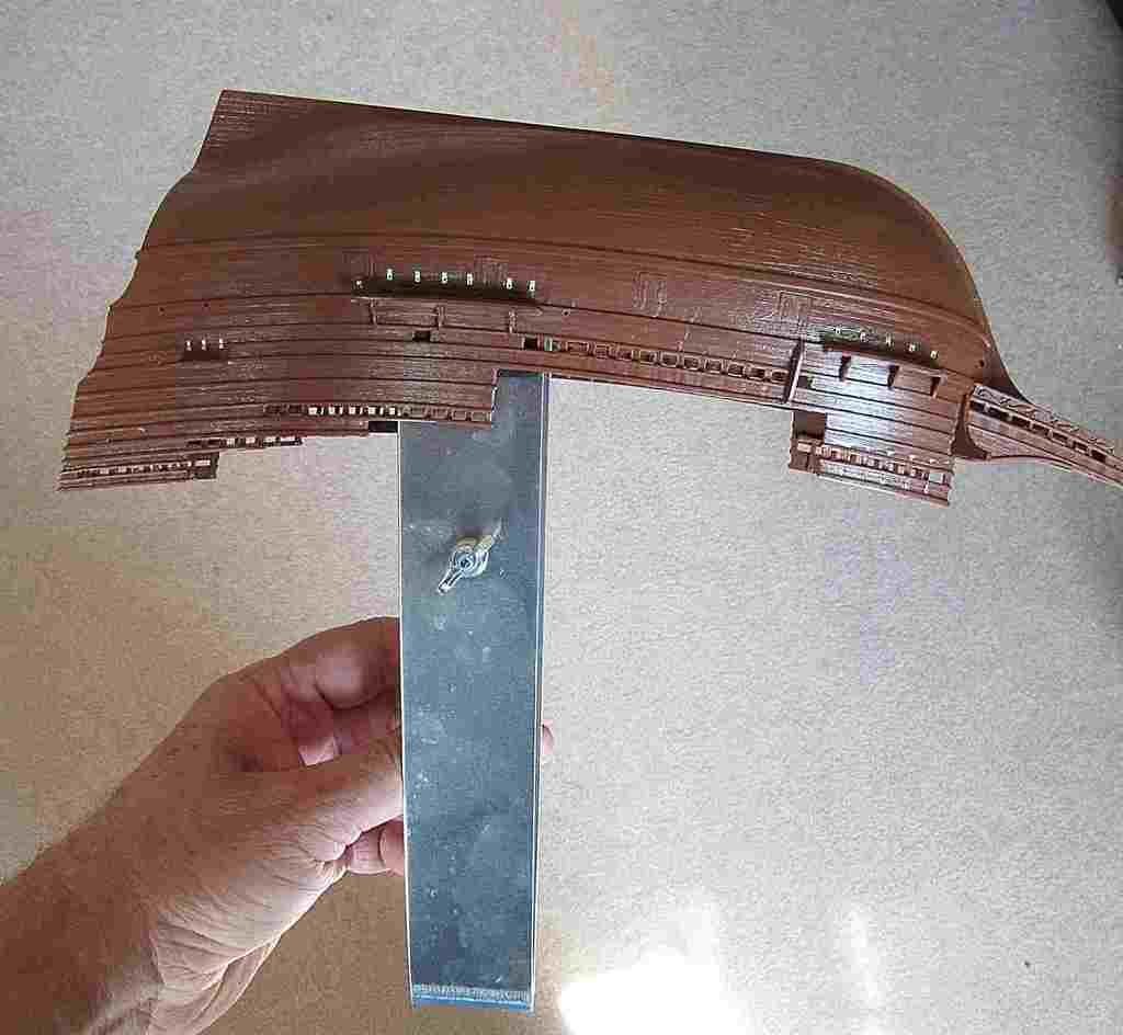
I worked on masking the windows today. I have not worked with Bare-Metal Foil before but I thought that it might be a good fit for this application. I say that mainly because of the tight fit. My first impression of BMF is that it is thinner and more pliable than I had expected. So, this was a good thing, and it worked well for this. There was of course a small learning curve to find the best way to apply it. 

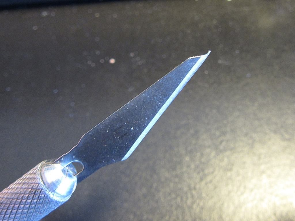
I began by practicing with it on my spare transom. As usual, with trimming out the masks, it always seems that it is the corners that are the problem areas. I don't get a clean cut and that causes the mask to be pulled up along with everything else. I tried different types of blades when I found the one below from within my stash. This blade seemed to work much better than the curved and/or standard blades that I tried. I was able to get a nice easy cut. Notice the really small tip at the end. I will have to remember this blade for when I am working on masks.

An important part in this process is to burnish the BMF to the windows. I started by using a cotton swab for this purpose. It wasn't long that I started to see cotton fibers sticking to the BMF. I suppose that I could pick off all of that by hand, but who needs that grief. It was time to find a better way.

Below: Notice the cotton fibers

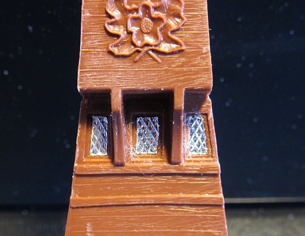
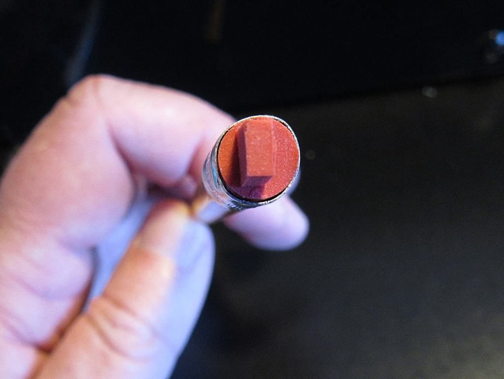
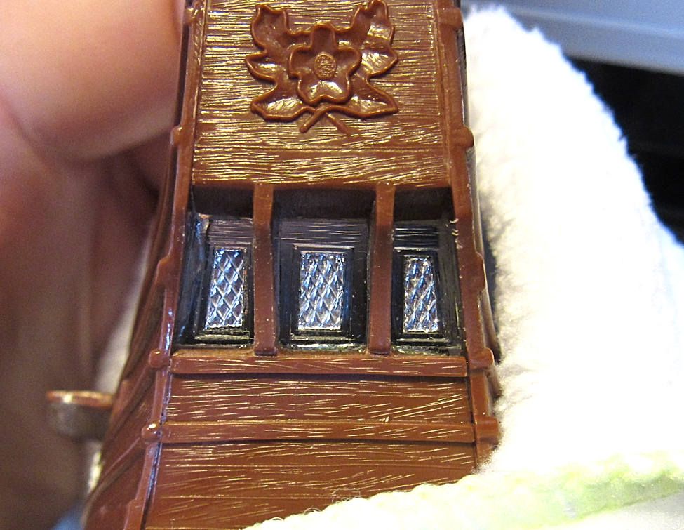
I needed to use something firm, but yet pliable in order to get the proper relief detail. The image below is what I came up with. I trimmed this eraser so that it would fit into the window openings. This eraser hack worked fairly well, and now, no cotton fiber to deal with.

Below: Here is how it turned out.

Since I am on a blabbering roll, here is more blabber for you.

Below: This little gizmo was a Christmas gift. My family needed gift ideas for me and what do you get a guy that pretty much buys what he needs. I noticed this item in the Micro-Mark catalog. To be honest, I probably would not have purchased this on my own, I would have come up with a solution by using something that I already have. This item sells for something like $15. But hey, I can use it, and they needed a gift idea. 

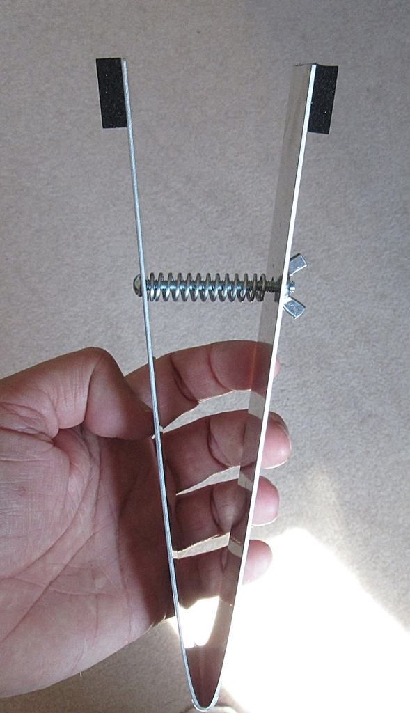
I did have to modify it though. They made the device so long that it could double as tongs for a barbecue pit. So, I had to shorten it by about 4 inches or it would not clear the ceiling of my spray booth. The image above is after being shortened.

And there you have it. I will let you know how it works out.

  • Member since
    July 2013
Posted by steve5 on Monday, April 18, 2016 1:08 AM

you are an ingenious fellow steve .


  • Member since
    July 2014
  • From: Franklin Wi
Posted by Bakster on Monday, April 18, 2016 3:55 PM

Steve, thanks for the kind words. I wish had more progress to show but my time has been extremely limited to work on this. It has been very slow going. With some luck, I will be hitting it with some paint by the weekend. Nothing exciting though... just some primer.

Thanks for following along and chiming in, Steve


  • Member since
    July 2014
  • From: Franklin Wi
Posted by Bakster on Sunday, April 24, 2016 12:44 PM


Then there was primer, and it was good


Decanted Tamiya Gray Fine Surface Primer thinned with Mr Leveling Thinner. This combination makes the paint go on like a dream. Just my opinion of course, but the primer seems to do a really nice job preserving surface detail. In combination with the thinner, I had no AB issues at all. No splatters, no clogging, no sandpaper finish, and no paint buildup on the tip. The final finish is smooth and detailed.

One of these days I will try using TFSP with hardware store lacquer thinner. I'd like to confirm if MLT is part of the magic. If not, then why pay the price and deal with ordering it on-line.


The Micro-Mark holder worked fine. It does a nice job of firmly holding the piece while you AB. The adjustable screw works well to that end. You can even hang the painted piece by the handle for drying. 


  • Member since
    July 2014
  • From: Franklin Wi
Posted by Bakster on Monday, April 25, 2016 10:06 AM

Important message from the OP

Hello everyone. I am roughly halfway through this build and I feel that it is a good time to take a moment to reassess this WIP.

My reason for starting this WIP was that when I looked around the ship forum there seemed to be a real lack of WIPs. With just starting my Mayflower build I thought that what the heck, I will do my part and try to contribute. Being a newbie to ships, I know that I don't have much to offer. Heck, I am pretty much a newbie to scale modeling as well. I had hoped that my lack of knowledge might be helpful to others that are in the same boat, and that maybe I could bring some fun to those that are not. I have been doing the best that I can to make things interesting for you folks.

Lately, I have noticed a very palatable lack of interest in my WIP. In truth, other than the early flurry of posts and subsequent helpful posts by Jtilley and GMorrison, the posts have been next to nothing throughout the greater portion of this WIP. Crickets comes to mind. It is clear to me by the number of views that people are looking, just not participating. Maybe my WIP is not comment worthy, and this is the crux of todays message.

Does anyone have an interest in me continuing? This is the time to speak up. WIPS can be a fair amount of work and if there isn't a real interest or value in what I am doing, I will go on my merry way and finish this build off-line.

Thanks in advance for your responses.

PS: No response is a response.


Steve


  • Member since
    September 2012
Posted by GMorrison on Monday, April 25, 2016 10:25 AM

Of course, and I am following along. You've sort of gone into some detail that shows you don't need advice, cooking along.

Remember you are building for you.

BTW about to start a WIP for my Type 21 U Boat. It's involved a serious amount of pre-painting, but I'm almost there. Looks like we will be painting our hulls together.

 Modeling is an excuse to buy books.


  • Member since
    May 2003
  • From: Greenville, NC
Posted by jtilley on Monday, April 25, 2016 10:54 AM

Of course you should continue the posts, Steve. It's going to be a fine model.  I'm quite sure that plenty of people are following along, and just haven't been able to offer suggestions.

Did you look at the "Views" figure at the beginning of your thread? It's been viewed more than 14,000 times. That's more than twice as many as my Hancock thread.

I gotta tell you though: I'm afraid your projection that the model is halfway done is a bit over-optimistic. You've got a long way to go.

One question: have you decided how you're going to mount the finished model? The stand that comes with the kit isn't bad, but if you want something fancier you need to make provisions for it about now. And unless you have room in a glass-fronted piece of furniture (like a curio cabinet), it wouldn't be a bad idea to start thinking about a case.

Hang in there.

Youth, talent, hard work, and enthusiasm are no match for old age and treachery.

JOIN OUR COMMUNITY!

Our community is FREE to join. To participate you must either login or register for an account.

SEARCH FORUMS
FREE NEWSLETTER
By signing up you may also receive reader surveys and occasional special offers. We do not sell, rent or trade our email lists. View our Privacy Policy.