SEARCH FINESCALE.COM

Enter keywords or a search phrase below:

Revell 1:83 Mayflower

50273 views
601 replies
1 rating 2 rating 3 rating 4 rating 5 rating
  • Member since
    May 2003
  • From: Greenville, NC
Posted by jtilley on Thursday, February 25, 2016 10:29 AM

Good point. I favor the "links per inch" designation. The idea of identifying chain as "HO scale," or "1/350 scale" makes no sense - for the simple reason that real chain comes in so many sizes. (The links of a destroyer's anchor chain are way smaller than those of a battleship.) Unfortunately, though, asking the hobby industry to standardize on anything seems to be asking for the hopeless.

Youth, talent, hard work, and enthusiasm are no match for old age and treachery.

  • Member since
    May 2013
  • From: Indiana, USA
Posted by Greg on Thursday, February 25, 2016 10:55 AM

Shame on me for not following this project, Steve.

I am really impressed with your attention to detail and research and.....

Bow Down

Now that I've finally found this thread, hopefully I can follow along.

I see you have some really great expert help and advice going on. How can it get any better?

  • Member since
    July 2014
  • From: Franklin Wi
Posted by Bakster on Thursday, February 25, 2016 11:00 AM

Agreed.

"Unfortunately, though, asking the hobby industry to standardize on anything seems to be asking for the hopeless."

I like this quote so much, I might add it to my signature!

  • Member since
    July 2014
  • From: Franklin Wi
Posted by Bakster on Thursday, February 25, 2016 11:14 AM

Say, Greg! It is great to have you aboard! Be sure to wear your life jacket at all times.  This ship is not sea worthy... Yet!

Seriously, I am glad you found it and thanks for the kind words. And Greg, the help here is off the scale. You can't walk away from their input and not learn something. You are so right. It can't get any better than this.

I am glad you found me and I look forward to hearing from you more. Welcome Sign

  • Member since
    July 2014
  • From: Franklin Wi
Posted by Bakster on Monday, March 7, 2016 9:24 PM

First of all, I would like to apologize for yet another tiresome reference to this ships transom. Having said that though, this update is somewhat of a milestone in the build and so I wish to document it.  

The transom has been glued in. This ship has evolved from an open structure to what I now consider a hulk. I suppose in theory, it could be buoyant if required of it. 

The transom was so ill-fitting that I had to install it in three stages. I at first worked on the lower section, then the top right, and then the top left. I let a day go by between each stage to ensure the glue was properly set. Thank goodness for rubber-bands because with the odd shapes and slick surfaces, I was not able to use clamps.

In the end, I am pretty happy in how the joins turned out. I applied epoxy to the backside of the joins as well to add additional strength. I will install the main deck after paint and that will put some stresses on the hull with trying to getting it in there. I don't want to pop the joins after I have the hull all nice and perdy with paint. 

Below: The first stage.

Below: The end result.


Below:  Also installed are the catheads and chesstrees. Sadly, the chesstrees are ill-fitting as well. Oversized mounting-holes are provided for these pieces and I don't know why. I will add some filler to try and minimize some of the gaps.

Taking a page from Walter Cronkite and in how he would end his news updates: And that's the way it is, March 7, 2016.


  • Member since
    July 2013
Posted by steve5 on Monday, March 7, 2016 11:32 PM

really nice work as usual steve , gee I'm enjoying this build , but I have a question . as I have this kit in my stash , I was looking at the two gun port's on the transum , thinking to myself if I could open them up . then I thought they look below the water line , if they are do you know what they are .


  • Member since
    July 2014
  • From: Franklin Wi
Posted by Bakster on Tuesday, March 8, 2016 9:04 AM

Hey Steve, thank you sir! 

To the best of my knowledge those two ports are used for canons. This is what Wikipedia had to say about it:

The gun room was in the stern area of the gun deck, to which passengers had no access due to it being the storage space for powder and ammunition for the ship's cannons, and any other guns or weapons belonging to the ship. The gun room might also house a pair of 'stern chasers', small cannons used to fire out the stern of the ship." 

Maybe others can clarify further.

Opening up the gun ports would be an awesome thing to. It would be great to see you do that! By the way.  Docidle Steve posted a link several weeks back to a Mayflower build where they did just that. It is very cool to see. Scroll back on this thread and you should be able to find it.

Here is an image of the replica showing the waterline.


  • Member since
    September 2012
Posted by GMorrison on Tuesday, March 8, 2016 10:35 AM

Opening the two ports would be a nice touch. The molded ones look bad.

Don't try to save them. Drill and cut the opening, and file to shape. I't a little tricky now because you will need to build up the thickness of the hull to show whatever the inboard framing members are on each side of the ports, and probably the bottom. But I think if you fish around a little with strip styrene you'll be fine. A trick when framong gun ports that cannot be seen from inside, is to do a verticle thats long top and bottom, hten  a horizontal across the bottom thats butted against the vertical on one side and long the other way, then anothe vertical thats butted at the bottom onto the horizontal and long at the top. Much easier that trying to cut the bottom horizontal to length between two verticals.

 Modeling is an excuse to buy books.


  • Member since
    July 2014
  • From: Franklin Wi
Posted by Bakster on Tuesday, March 8, 2016 10:56 AM

Yes it would be a nice touch for sure.  Maybe on a future build I will put my teeth into it more. But, Steve 5, there you go. Something more to think about with GMs thoughts on the subject.

  • Member since
    September 2012
Posted by GMorrison on Tuesday, March 8, 2016 11:33 AM

They are not a really noticeable part of the ship. Maybe just hit the outline with a scribing tool and call it a day. The diagonal planking on the transom actually is more interesting. That shows up pretty well in the photo of the replica, and is very pronounced on wooden POB kits, for obvious reasons. I'd scribe those a little.

 Modeling is an excuse to buy books.


  • Member since
    July 2014
  • From: Franklin Wi
Posted by Bakster on Tuesday, March 8, 2016 1:16 PM

I beseech thee Master Morrison that these are grand ideas indeed. 

I will have to store them in the ships hold of my memory. I have not mastered the process of scribing yet. Any attempt that I have tried on models thus far has always made me wish that I never attempted it. It looks like all heck. So in this case I will move on and not temp fate.

Thanks though. I am sure your thoughts will helps others in the more immediate future. 

  • Member since
    July 2014
  • From: Franklin Wi
Posted by Bakster on Sunday, March 13, 2016 8:50 PM

Greetings Folks.  I have a very novice question for you today. Is there a name associated to the feature circled below?  Or is it just part of the beakhead and there isn't a name assigned to it?  

  • Member since
    September 2012
Posted by GMorrison on Sunday, March 13, 2016 9:00 PM

I would call it the knee. It's one component of the beak head, which is most everything else in that illustration, except the spars.

 Modeling is an excuse to buy books.


  • Member since
    July 2014
  • From: Franklin Wi
Posted by Bakster on Sunday, March 13, 2016 11:05 PM

Thanks for the info GM. I am pretty sure that I have referenced this section before and I had mislabeled it. Going foward I want to set it right.

Thanks again.

  • Member since
    July 2014
  • From: Franklin Wi
Posted by Bakster on Tuesday, March 15, 2016 11:20 PM

When I started this WIP I was determined to show the good, the bad, and the ugly. I still am, and here is some bad for you.

I snapped off the knee. I did it not just once, not twice, but three times. After the third time of fixing it I said, "(Bleep) it. I will fix it once I get closer to paint." 

It happened earlier on in the build and always when I was working on the transom. It's crazy. No matter how careful that I tried to be, I invariably, unknowingly, had the beak resting on my leg and then... snap! It's not the worst thing in the world, it just creates more work. So for anyone building this kit, be advised.

With this repair I did something different. Rather than just gluing the knee to the hull like I did before, I instead glued it to the triangular piece first. I did it this way because I was able to align the broken piece better with it resting into the other.

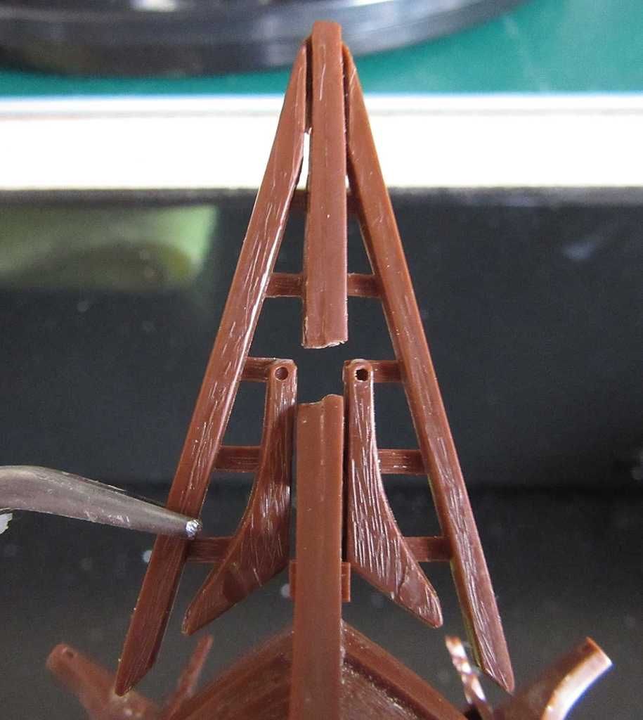
Below: The problem as viewed from underneath and looking up.
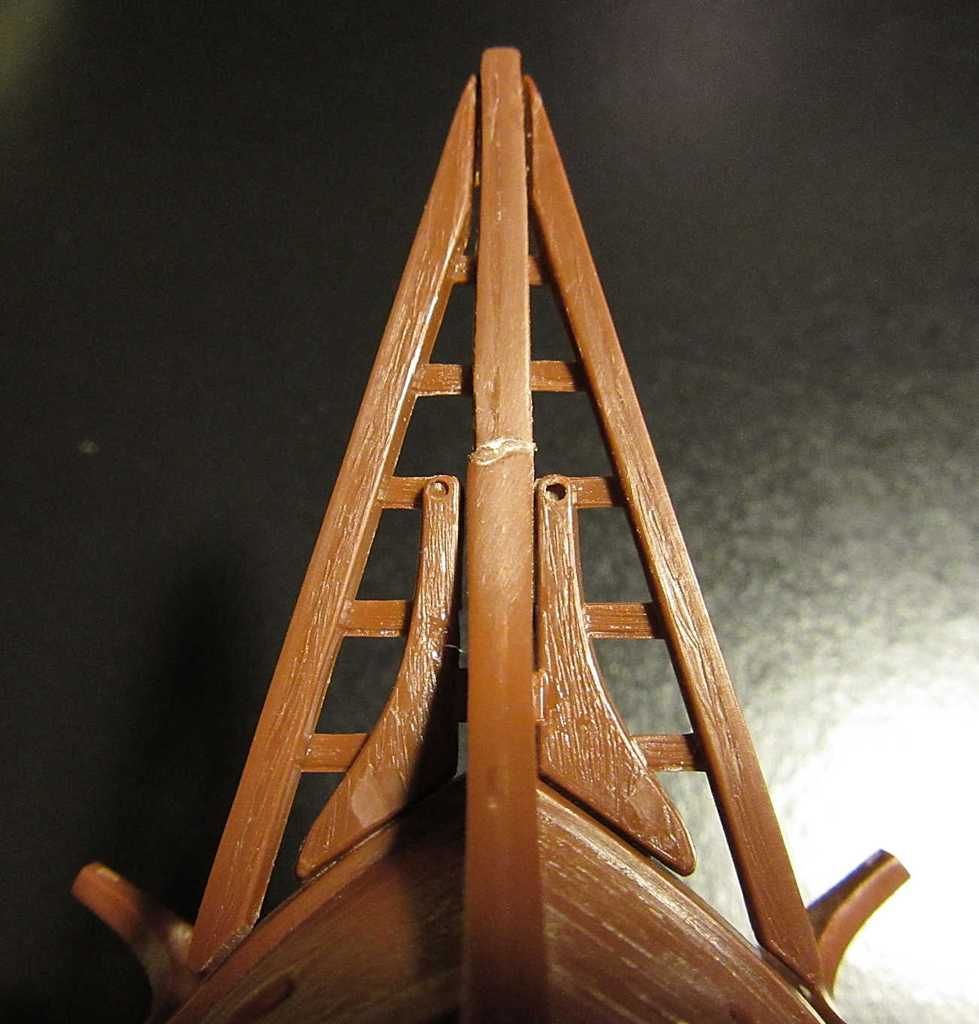


Below:  Glued in.


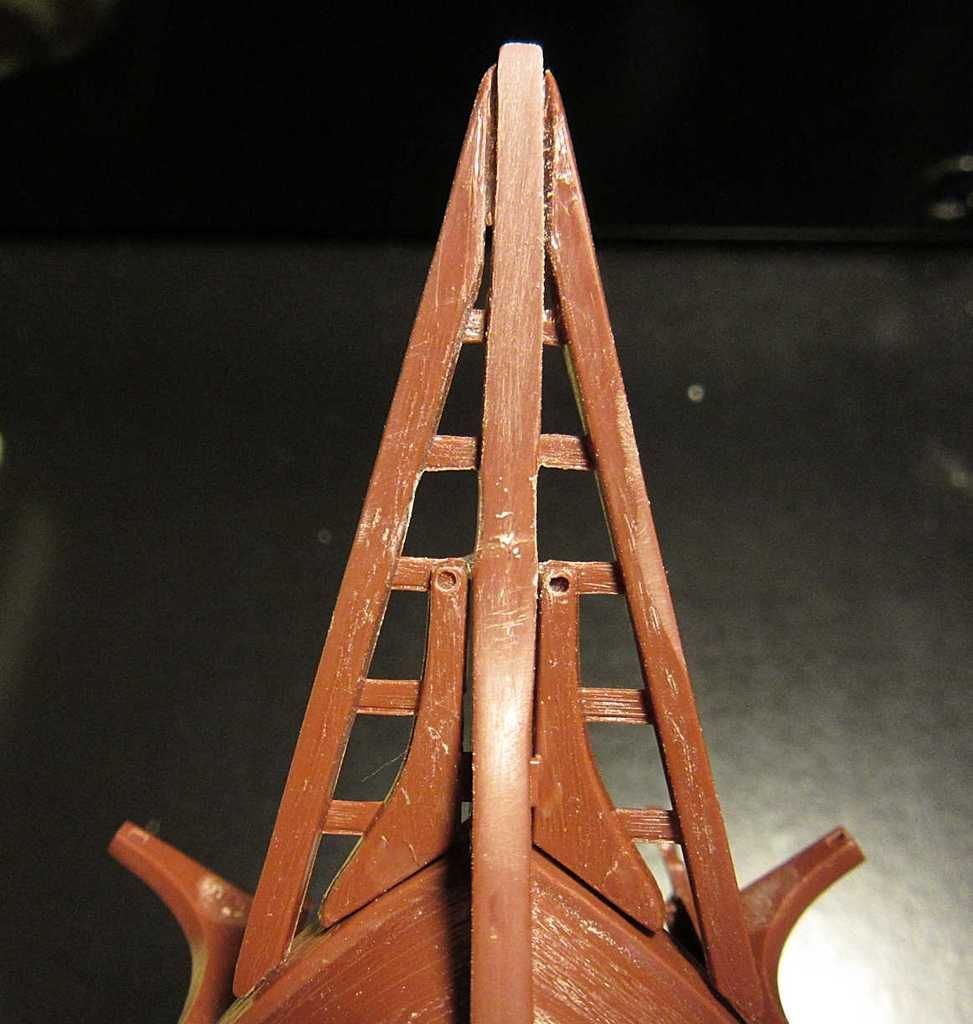
Below: Some plastic surgery using CA as filler. It's not perfect, but close enough for me.

And that is that.

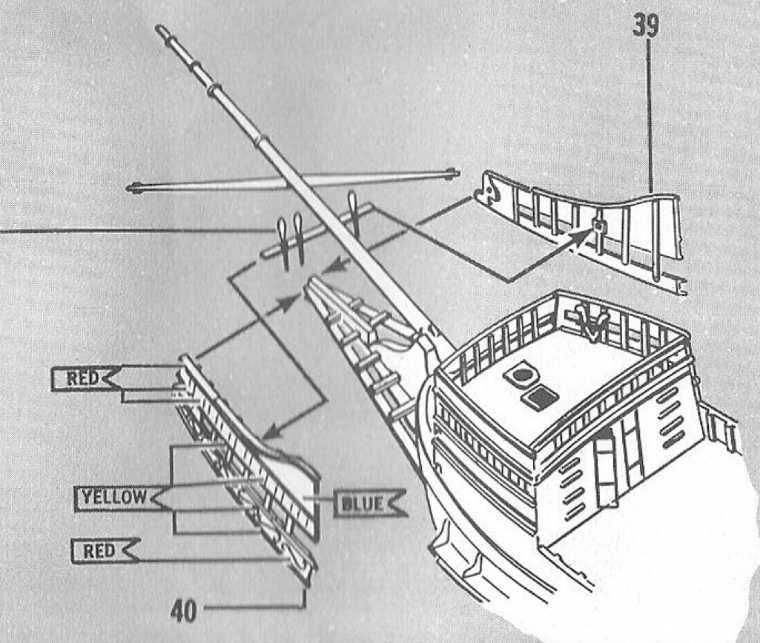
This assembly is tricky to align correctly and if you get wrong, it just won't fit, nor look right. This is especially true when installing the beakhead rails. If these first steps are wrong, the rails won't fit right, and the rails are a very noticeable part of the ship. It took a lot of test fitting, but I think that I have it correct now.

My next dilemma is if to install the rails now, or after paint. I have to ponder that more. I am leaning to after. It will make painting easier. The downside is that it will be a little harder to get nice solid joins.

So, I have the rails to consider, then mask the transom windows, then prepare for paint.

Anyway, this is where this build stands. As a reference, the beakhead rails are shown below as number 39 and 40.


  • Member since
    September 2012
Posted by GMorrison on Wednesday, March 16, 2016 9:37 AM

The fix looks good, but you are right it isn't strong. You might try using plastic solvent insted, CA kind of sucks.

You should put her on a base at this point.


 Modeling is an excuse to buy books.


  • Member since
    July 2014
  • From: Franklin Wi
Posted by Bakster on Wednesday, March 16, 2016 9:59 AM

Thanks Morrison.  With this repair I did start with solvent, then added the CA to create a smoother line to the repair. With my previous repairs, I did use CA, and you are absolutely correct.  The CA did not hold up well. I am gaining a far greater appreciation for solvent and I use it whenever possible. I do love CA as a filler though. 

  • Member since
    July 2014
  • From: Franklin Wi
Posted by Bakster on Wednesday, March 16, 2016 10:10 AM

I forgot to respond about the base. I have been using the kit stand but with it being plastic, it slides around too much.  I added some tape to the pressure points and that helped some. Still, the stand is a three point system and its fine for display, but not for working on the ship. I need to make something better.  Good point GM

  • Member since
    July 2014
  • From: Franklin Wi
Posted by Bakster on Saturday, March 19, 2016 4:11 PM

The more that I test-fit this assembly the more that I knew I had better just glue it together now, before paint. I had to do a little more surgery here and there and I even had to do a little heat-treating to warp the knee some.  All this manhandling would surely start to make a mess of a nice paint job had I waited until later. 

Below are some images of how she looks thus far.


  • Member since
    July 2014
  • From: Franklin Wi
Posted by Bakster on Sunday, March 20, 2016 12:51 PM

It is amazing what a photograph reveals that I couldn't see with magnifiers.

Prior to posting yesterdays images I had noticed that the cutout (noted in the image below) was barely visible. This would make gammoning the Bowsprit an impossible task. That opening was pretty much closed off by the beam/floor timber assembly. I wrote this off as that I misaligned something. In the back of my mind I was already thinking about how I was going to get that open again. When I looked closer at the bottom view image, it had dawned on me to take another look at things. I decided to pop 1 and 2 glue joins. (See the positions noted on the second image below.)

What do you know. The opening in the knee showed up so that now I will be able to thread string through it. So, it appears that 1 and 2 had to be mounted not above the tabs, but more next to them. At least in my case it is. If I try mounting below the tabs then things get pretty wacky, and it does nothing more to improve the opening.

I mentioned before that this assembly is pretty critical in its alignments. We are talking a miniscule adjustment here and it made a big difference. The instructions don't indicate either way how that piece should be positioned and so it is trial and error.

Lastly, for anyone building this kit: I should mention that since the alignments are so critical it may not work out the same for you as it did for me. How I positioned other areas of the assembly may tweak things differently. The thing to take away from this is in how that piece and its positioning seems critical to opening up the hole for gammoning. I should also mention that you may not want to follow my order of assembly. With mounting the beakhead rails as I did, it will make gammoning a much more difficult task with the close quarters. I also opted to wait on installing the pinrail. That too will be a little more difficult to install. Actually, there are many things that I don't follow the instructions on verbatim. I have my reasons for doing things the way I do, mostly having to do with paint and perceived structural integrity. I am probably stating the obvious here, but I do not want to lead anyone down a path that may not work for them. This is my WIP disclaimer and I won't bother you with it again. Indifferent

Sorry for the long read.


  • Member since
    July 2014
  • From: Franklin Wi
Posted by Bakster on Wednesday, March 23, 2016 9:16 PM

In all likelihood I will not have anything more to post on this for a few weeks. It is time for paint and I have some updates to do on my booth that will delay things a bit.

However, here is something for you. You probably do not know this but that in-between things I have been working on a Mayflower ship in the bottle. It is now complete. I thought that you might like to see it.


I could not resist.  I thought it a good time to lighten things up some around here.

Cheers!


  • Member since
    July 2014
  • From: Franklin Wi
Posted by Bakster on Thursday, March 24, 2016 1:04 PM

"Tough sub"

  • Member since
    July 2010
  • From: Tempe AZ
Posted by docidle on Sunday, March 27, 2016 5:16 PM

Steve,

I think I see where the problem is. Pieces 39 and 40 are sitting a tad too low which means the grating is sitting a tad low also. I broke out the 6 year old model of the Mayflower I was working on and quickly reglued the pieces back on to show you. Needless to say the painting and glueing are more than a bit rough. The upper railing on 39/40 should align with the rail on the hull. 

This will also raise the grate up enough to open the gammoning hole. Also gammon around parts 1/2 in your labeled picture. You'll also note that I had broken the stem piece off as well!  Hopefully this will help.


Steve


  • Member since
    July 2014
  • From: Franklin Wi
Posted by Bakster on Sunday, March 27, 2016 7:55 PM

Hey Steve, thanks for the input and for pointing that out. That of course makes sense and I think that you are 100% correct. The problem that I had was that when I aligned 39 and 40 to the upper railing as you have it, then the beak/knee seemed to stick out too much below pieces 39 and 40. All the images that I could find on the actual replica show the knee tucked below those panels. Your example looks pretty good though, better than what was able to get. So, it shows that it can be done. Obviously, I had something messed up. It looks like I will have to try popping those joins and do it again. Dang it!!!

Thanks for the heads up.

  • Member since
    July 2014
  • From: Franklin Wi
Posted by Bakster on Sunday, March 27, 2016 8:41 PM

Steve, I popped one side off. I just tried aligning the panel to the upper rail and things seem to look ok. BUT, that gammoning hole is covered up by the grating. Is the hole supposed be above the grating? Or does it go below? I assumed it should be above. In order to open it so that the hole is above I have to pull down on the grating. Then by doing that, the back section (Noted as #1) of the grating sticks out below the panels.  What am I missing here?


  • Member since
    July 2014
  • From: Franklin Wi
Posted by Bakster on Sunday, March 27, 2016 8:51 PM

PS: Looking closer at your example, it looks like the hole is below the grating.  So if that is true, then the gammoning will wrap around the grating?

  • Member since
    July 2010
  • From: Tempe AZ
Posted by docidle on Sunday, March 27, 2016 9:57 PM

I believe so, but let me look at the instructions and get back with you. But if memory sreves me right, then the gammoning hole is below the grating and wraps around the grating also.

Steve


  • Member since
    September 2012
Posted by GMorrison on Monday, March 28, 2016 11:07 AM

Looking at pictures of the replica, it appears that there are two gammons, one inboard and one outboard. When you say "wraps around the grating", is that suggesting that there's a component of the grating part glued along the side of the knee and that gets including inside the gammoning. I'd cut that little section off.

 Modeling is an excuse to buy books.


  • Member since
    July 2014
  • From: Franklin Wi
Posted by Bakster on Monday, March 28, 2016 1:53 PM


Hey GM—

That is pretty close to what I am suggesting. If I move the grating so that hole is below it, then yes, things get in the way. If you look at my 3/20 posting, the last image looking at the underside of the beak assembly, you will see how the grating is aligned alongside of the knee. There is a very narrow gap in there that I might be able to fish the string through for gammoning but it seems odd. Is that how I am supposed to do it? Or does some of that inner grating get wrapped as well? I really do not know how this is supposed to be done because the instructions are not anywhere near detailed enough for me to figure it out and I have not been able to locate any documentation showing better.


  • Member since
    May 2003
  • From: Greenville, NC
Posted by jtilley on Monday, March 28, 2016 4:30 PM

Well, Dave, I've studied your photos and some shots of the real Mayflower II, the Revell Germany instructions, and the instruction book for the Model Shipways wood kit. (It can be accessed here: http://www.modelexpo-online.com/images/docs/MS2020/MS2020-Mayflower-Instructions.pdf . It wouldn't be a bad idea to print out a copy. The beak structure is described around p. 21.) I would have looked at my old Revell kit, but I can't lay hands on it. Mr. Passaro, who designed the Model Shipways kit, seems to have interpreted the arrangement of the stem and the gammoning knee a little different than Revell did. To my eye, both versions look sensible.

To me, it looks like the bottom line is that, in Revell's version, the gammoning slot (there's only one; I can't find the second gammoning that GM was talking about) is supposed to be above the part that makes up the beams of the beak structure (part 37). That part apparently is supposed to sit on top of those two little tabs. (By the way, the tabs aren't prototypical; you could shave them off.) Part 37 incorporates two big, horizontal knees that are supposed to be fayed flush to the stem knee. (I think that's the name for it.) They support it horizontally, as the knee below it (molded integrally with the hull halves) supports it vertically. And the gammoning hole is just above them. So the gammoning goes around the bowsprit and through the gammoning slot - period.

I'm not sure what went wrong here, but the problem may be due to the age of the molds. (The kit, after all, was originally released in 1966. Those molds are at least fifty years old.) Maybe the gammoning hole has gotten a little plugged up and shrunk a bit. Maybe the little tabs have gotten fatter. Or maybe they weren't molded right in the first place.

At any rate, the fix I'd suggest is: 1. Shave off the two little tabs on the knee. They aren't authentic. 2. Trim part 37 so it fits tightly over the knee, and glue it. 3. If necessary, file the gammoning slot a little wider. (For heaven's sake, make sure the rope you intend to use for the gammoning fits through the slot - seven times. The slot is far more accessible now that it will be later.)

I think that will solve the problem - though I'd be more certain if I had the kit in front of me.

Youth, talent, hard work, and enthusiasm are no match for old age and treachery.

JOIN OUR COMMUNITY!

Our community is FREE to join. To participate you must either login or register for an account.

SEARCH FORUMS
FREE NEWSLETTER
By signing up you may also receive reader surveys and occasional special offers. We do not sell, rent or trade our email lists. View our Privacy Policy.