SEARCH FINESCALE.COM

Enter keywords or a search phrase below:

1/350 Scale Aircraft Diorama

15577 views
31 replies
1 rating 2 rating 3 rating 4 rating 5 rating
  • Member since
    March 2012
Posted by Rdutnell on Sunday, August 17, 2014 12:51 PM

UPDATE 2 – 8/17/2014

Good Morning,

I stripped the old base off the plywood board yesterday and sanded it in preparation for the new base, as seen below.


I also bought a can of Krylon UV-Resistant Clear Acrylic Coating (Matte).  I think I can apply several coats of this, to at least slow the fading down.  I may spray it with several coats of Future, then UV protection, or possibly the other way around..  When I plot it I will include test patches around the outside so I can test various methods before I do it on the real thing. 

As I said in my last post, the circuit board is 3/4" x 2" x 1/2" high.  My initial idea to make a box for it and paint it with a red and white checkerboard pattern won’t work as I thought.  The box would be too big.  Instead, I decided to make an office building, as seen in the images below. 

Here is the new plan view of it.  I should perhaps mention that this diorama is not intended to be completely realistic.  There isn’t enough space.  Instead, the intent is to provide an airport type setting while allowing the display of as many of my 350 scale models as possible.  I think I can probably get 3-5 more models on it (as long as they are small plans).  I’m also considering suspending a couple of 1/144 scale models from the lower shelf above where the base will be, as if in a holding pattern.


The next 2 images show the hangar side of the new building.  I added a draped awning, like ones I remember going through on AFB’s as a kid many years ago.  I also included a flag pole, although I don’t intend to print it.  I will use brass rod.


This image shows it zoomed in.  The picture is old as I have since added a sidewalk connecting the flag pole circle to the sidewalk.


The next image shows the building/circuit board cover from the runway side.  Note that the building includes a back door and that I added a snack area for people to sit and watch the planes take off and land.  I might have to make some tables with umbrellas, at some point, to fill the space.


On the model front, I gave the T-38’s a coat of Krylon ColorMaster Paint + Primer Gloss white.  I think all they will need is a very light second coat, and they will be good to go.


Although it isn’t shown in the pictures, I have also sanded the F-111A, and am preparing to start painting it in camo.

CHEERS!!!

  • Member since
    March 2012
Posted by Rdutnell on Saturday, August 16, 2014 1:53 PM

UPDATE 1 – 8/16/2014

In my initial post on this project WIP, I focused on what has been done on the base, hangars and tower.  I will turn now to the aircraft.  Fairly detailed descriptions of how I made the U-3A (http://cs.finescale.com/fsm/modeling_subjects/f/48/t/159017.aspx), T-34 and AC-47 (http://cs.finescale.com/fsm/modeling_subjects/f/2/t/157366.aspx), and a WIP for the Gulfstream G-IV (http://cs.finescale.com/fsm/modeling_subjects/f/48/t/159041.aspx) are provided elsewhere on the FSM forum, so I won’t repeat it here.  Nor will I provide a detailed description of the CAD techniques used to design them.  The steps are essentially the same, so I won’t bore you with the details.  If you are interested in the CAD details, go to the links provided above.

The image below shows the difference between the F-111TACT and F-111A.  The airframes are the same, but the wings are drastically different.  The TACT wing is shorter and wider that the A wing and has a curved tailing edge.  The modified wing was designed to reduce drag (and thus increase efficiency) and reduce the “sonic boom” effects of crossing the sound barrier.  The TACT wing was a precursor to the wings found on modern supersonic aircraft.


Although I am making these models for myself, Click2Detail (C2D) is now selling them on line, so I tried to design them to give modelers multiple options on how to display them.  Tabs are included to assure proper positioning of the wings and “Wings Forward” and “Wings Back” versions of both models are available.  The images below show the parts diagrams for the “Wings Back” F-111 models.  The “Wings Forward” versions are essentially the same. 


The picture below shows the parts for the F-111TACT.  They are pretty darn small!


The next two pictures show the F-111A after I had assembled the wings and stabilizers in preparation for priming.


The parts diagram for the T-38 is shown below…

…And a picture of the parts, as I received them from C2D is shown below.


The next two pictures show the F-111’s with a coat of primer on them.  Note the distinct difference in the wings on the two versions.  The pictures also show the primed hangars and the assembled T-38’s before primer.


I have also received the U-2R from C2D.


I am thrilled, because even the detailed antennas “porcupine quills” printed out nicely.


I have also received some models from Admiralty Model Works (AMW) who I am doing some design work in exchange for printing.  The models from AMW, include the AC-47 (minus a prop that I received later)…


…The U-3A (still in the bags I received them in)…


…The two El Caminos (still in the bags I received them in)…


…And the two F-5’s (still in the bags I received them in).


So, that’s where things stand on the project, with one exception.  Earlier I showed a modified top for the tower that I had printed.  This modified top was required because I decided to add a beacon light to the tower.  I found a company (Bakatronics LLC) on-line that makes a “Simulated Airport Beacon Kit”.  (http://www.bakatronics.com/shop/item.aspx?itemid=578)

The kit simulates rotation of White and Green Search Lights.  Quoting from their web site, “When power is applied the micro controller starts a sequence that slowly increases the brightness of a Super Bright 3mm White LED. The slow increase simulates the light beam rotating toward the viewer. The micro processor then flashes the White LED to simulate the light being directly in your line of site, then slowly decrease the brightness to simulate the light beam going away from the viewer. When the White LED is completely off, the same sequence takes place with the Green LED. The white LED is clear in the off state, so by positioning the Green LED directly under the White LED, the White and Green Lights seem to eminate from the same point.”

You can see a video of it at: https://www.youtube.com/watch?v=lTMh62EbJ-k&feature=youtu.be

The kit itself costs $19.99, but assembly and testing are available for $9.99, and I ordered 9-V battery clip and slide switch, so that with shipping, it cost me $35.65.

 The assembled kit is shown below, and reportedly measures 3/4" wide x 2" long x about 1/2" high.  My current plan is to make a box for it in AutoCAD and print it at OU.  It will fit nicely along the run way and will look good painted with a red and white checkerboard pattern.


As you can see, I still have a long way to go to complete this diorama project.  I’ll post updates, as they occur.

CHEERS!!!

  • Member since
    March 2012
1/350 Scale Aircraft Diorama
Posted by Rdutnell on Saturday, August 16, 2014 10:42 AM

Greetings All!

My name is Russ, and as some of you may know, I have gotten in to making 1/350 and 1/144 scale models, mostly aircraft using AutoCad, and having them 3-D printed.  I have posted, and am posting, WIPs of some of the models elsewhere here on FSM.  Some are completed, some are still in progress.  Some were made in collaboration with Ron, a master at building small scale models.

http://cs.finescale.com/fsm/modeling_subjects/f/2/t/157366.aspx

http://cs.finescale.com/fsm/modeling_subjects/f/48/t/158982.aspx

http://cs.finescale.com/fsm/modeling_subjects/f/48/t/159017.aspx

http://cs.finescale.com/fsm/modeling_subjects/f/2/t/160249.aspx

http://cs.finescale.com/fsm/modeling_subjects/f/48/t/160518.aspx

http://cs.finescale.com/fsm/modeling_subjects/f/48/t/159041.aspx

Knowing that eventually I would need to display the models that I am making, I started thinking about how I was going to do it, and thought immediately of doing a diorama.  This WIP will describe what I have done thus far, and document the process of completing the diorama, which could be a fairly long-term endeavor.   I am not an expert in CAD, by any means, and am relatively inexperienced at modeling, and any pointers, comments or suggestions along the way would be appreciated.

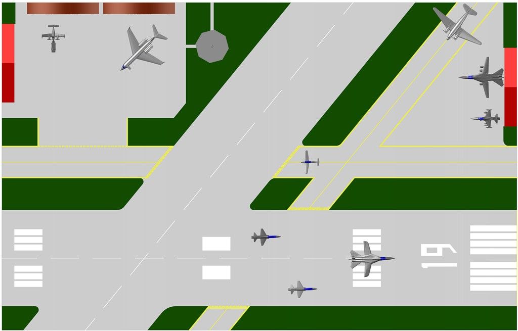
So, my initial thought was to make vignettes to fill a shelf that I have on one of my walls.  I measured the shelf, drew a rectangle with the measured dimensions in a CAD drawing and laid out the 1/350 scale models I had at the time, which included an F-111TACT, two T-38 Talon chase planes, an F-5A Freedom Fighter, and a U-3A Blue Canoe, and added a hangar façade. 


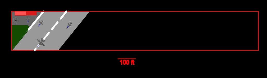
When I was a sophomore in High School, my dad, who was the Air Force representative in a joint project with NASA to put a super-critical wing on an F-111, took me out of school to watch the inaugural test flight at Edwards, AFB.  It was quite an experience and I want to replicate that moment, so I designed it for the F-111 to be just off the deck, one of the T-38s to have the nose gear just lifting off the deck and for the other T-38 to still be completely on the runway.  The U-3A, one of the planes my dad flew in his long career in the AF, will be parked as will the F-5A, which I made because it was a fairly easy conversion from the T-38.


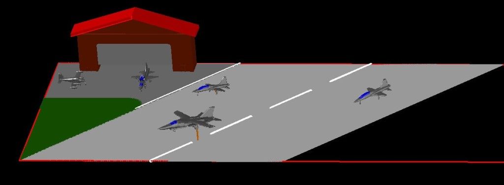
Then I decided to add an F-111A Aardvark, because it too was a fairly easy conversion.  This required moving things around a bit.


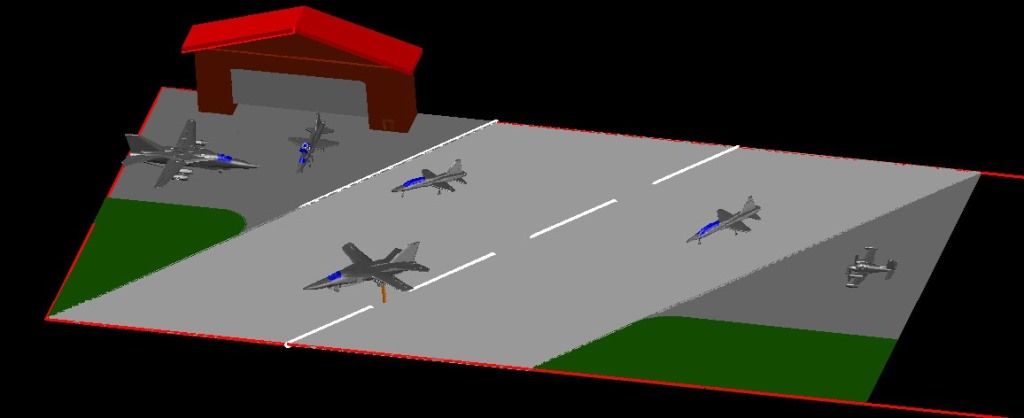
Then I decide to add the AC-47 “Puff” that dad flew in Nam.


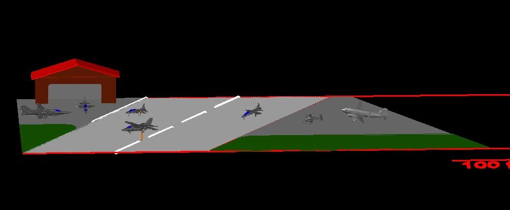
At this point, I changed my plan completely, abandoned the shelf, and decided to convert my cabinet shelf from a trash collector to a mini- airport of sorts.  I bought a piece of plywood and cut it to fit the space.


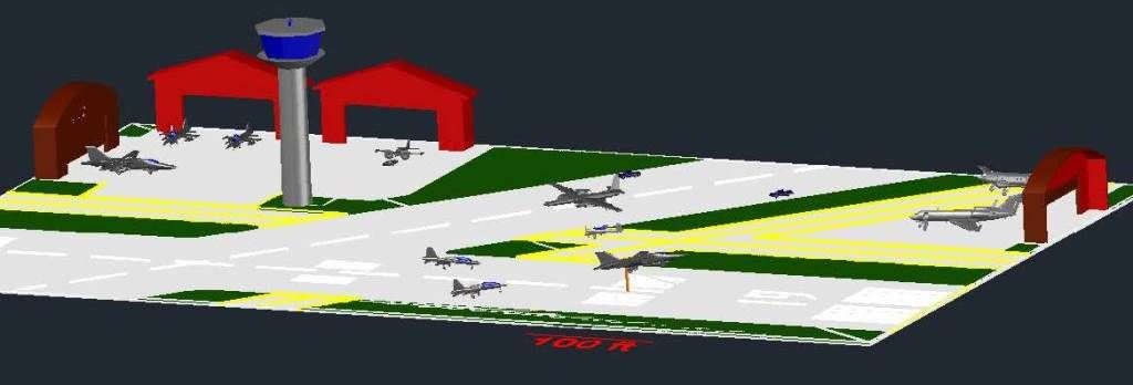
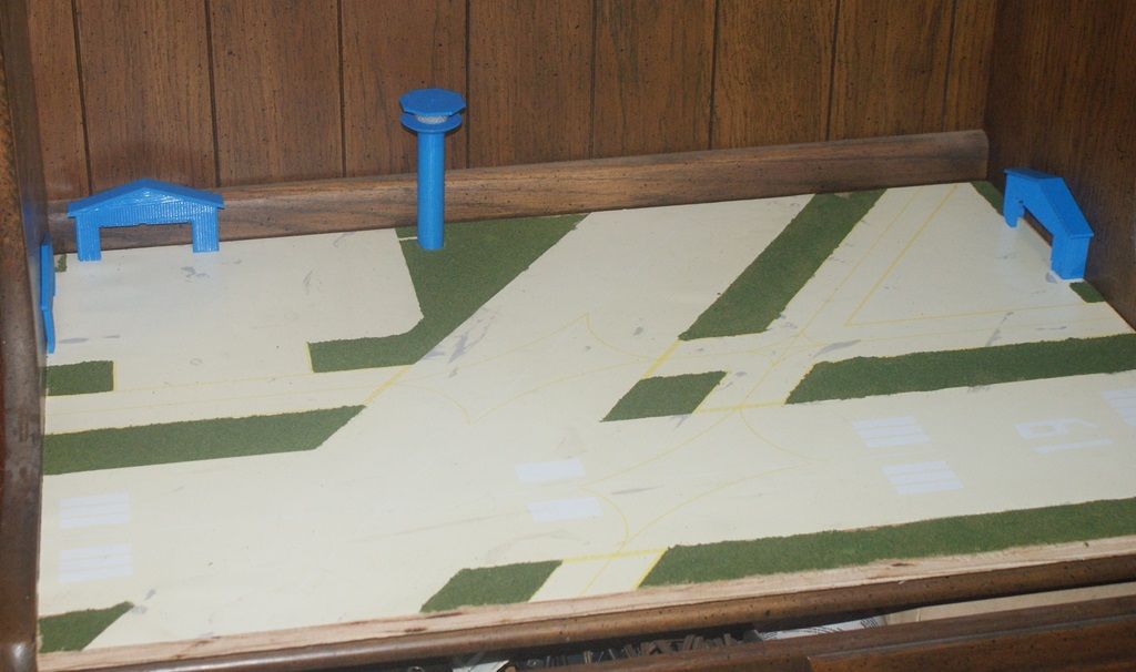
I repeated the process as before, developing a somewhat more elaborate layout, with a tower and three hangars.  I also added a LEKTRO tug, positioning it as if it were moving the U-3A.


Next I added a Gulfstream G-IV…


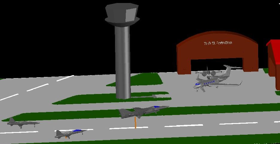
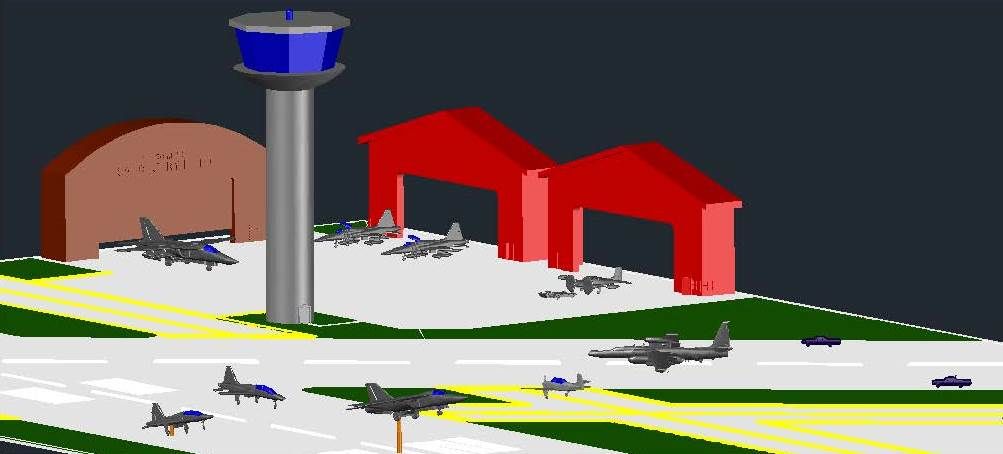
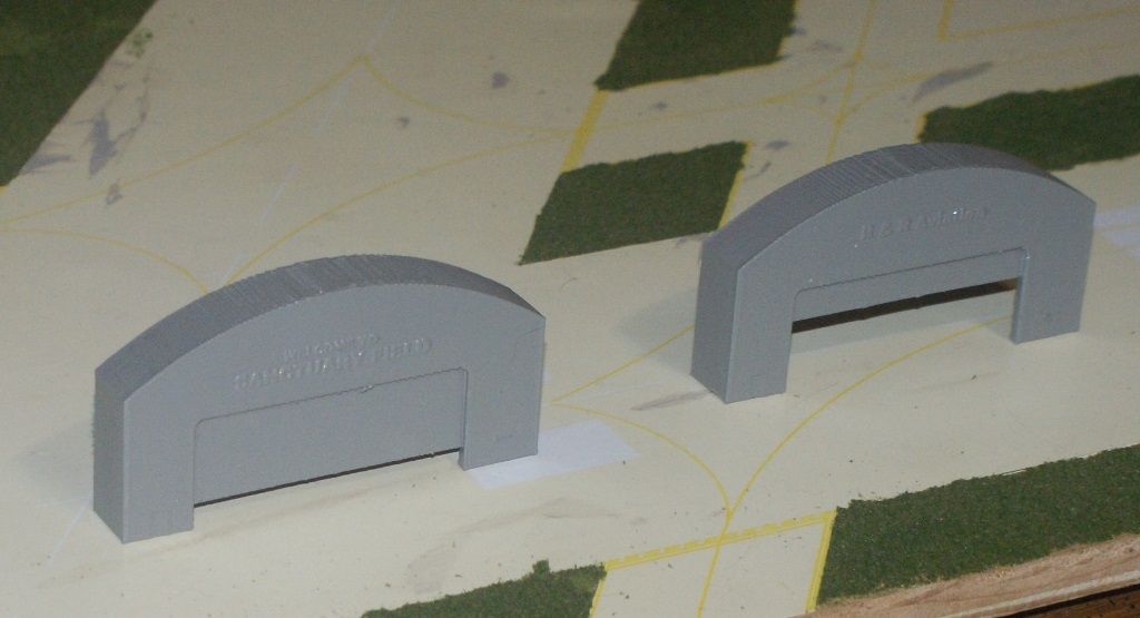
…And thought I would add some raised letters to one of the hangars, welcoming the viewer to Sanctuary Field.


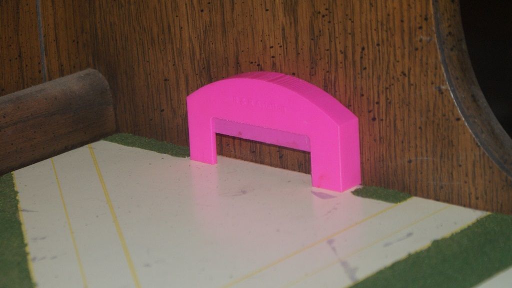
Isn’t that peaceful?  Sanctuary Field.  It sounds like a place where one could get lost in serenity.  But I digress.  It also pays tribute to Ron, who has been very encouraging in my foray into 3-D modeling.  On the other rounded roof hanger I added “R&R Aviation”.


At this point I plotted it out full size to see what it would look like.


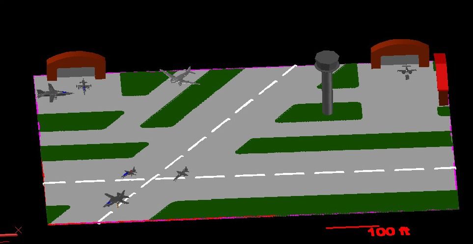
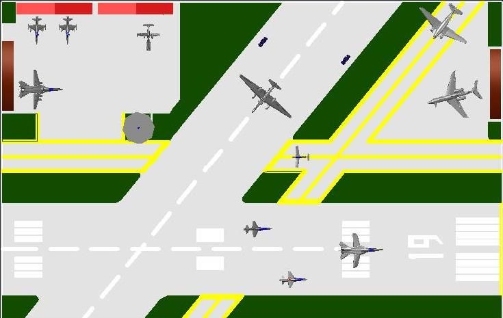
I kind of liked it, but realized, only at this point, that the hangar in the upper right hand corner would extend into the runway.  I know that it is just a diorama and not a true layout, but it bugged me, so I redesigned it.  Note that in addition to the markings on the runway, taxi lanes and tarmac, I also added a T-34-Mentor, and moved the tower.


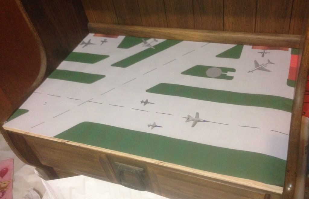
I then went to campus and printed the new layout on glossy poster paper, cut it out, and laid it in place to check it out.


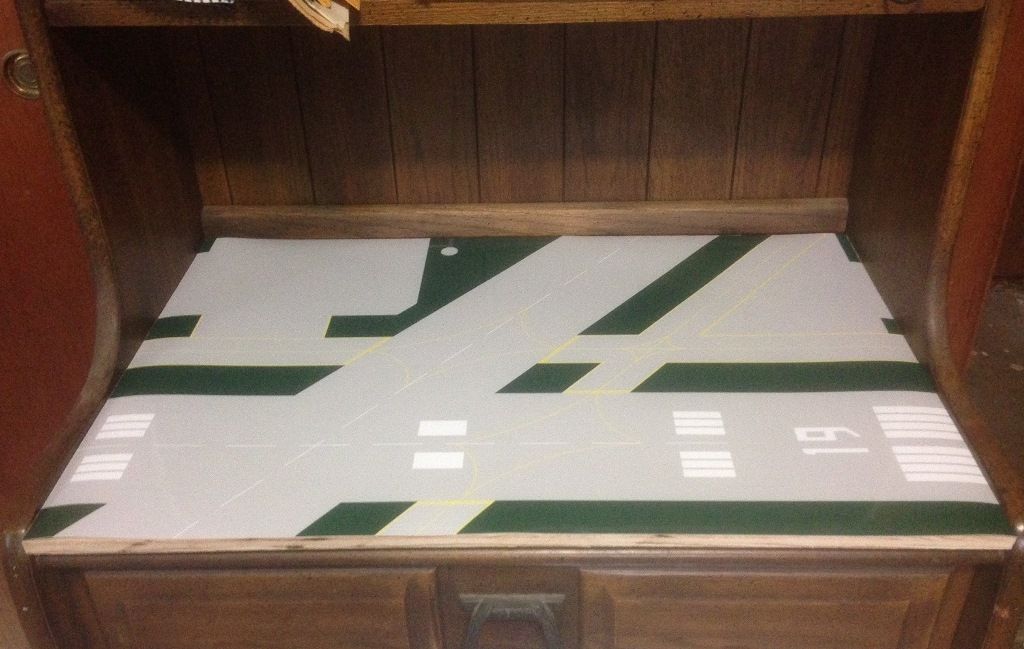
Satisfied with it, I cut out the grass areas and glued the concrete portion in place on the board.


I then used Woodland Scenic Fine Turf, gluing it in place with slightly thinned Elmer’s for the grass areas.


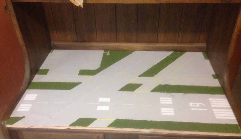
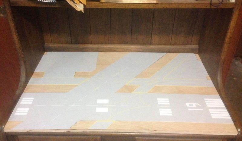
I didn’t do anything to treat the surface, and that turned out to be a mistake, as I noticed after some time that the gray had faded to a light yellowish color.  In the picture below, that looks grayer than it really is, you can see the color it originally was due to smudge marks I made when I glued the poster to the board.  I am pretty certain the fading is due to UV light.


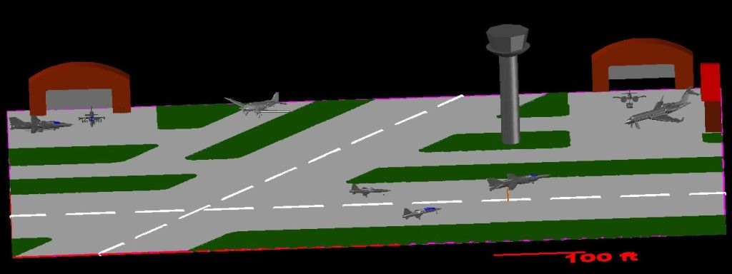
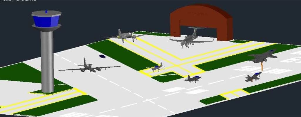
This means that I am going to have to redo it, but apply a UV protective barrier of some sort to protect it.  Since I am going to have to redo it, I decided to modify the design slightly, moving the tower to yet another location.  Note that I also added a U-2R being chased by two El Caminos, a scene I witnessed many years ago at Beale AFB.


That is where things currently stand with regards to the dio base, but I have made progress on other fronts as well.  The University has 3-D printers that students can use for free to print their 3-D models.  The quality of their printers isn’t good enough to print my detailed airplanes, but I thought it might be good enough to print the hangars and tower, and since it was free I decided to try it out.  The results were mixed.  I guess the printer goofed up, so they had to restart it.  The tower printed OK, which was encouraging, but the hangars did not.


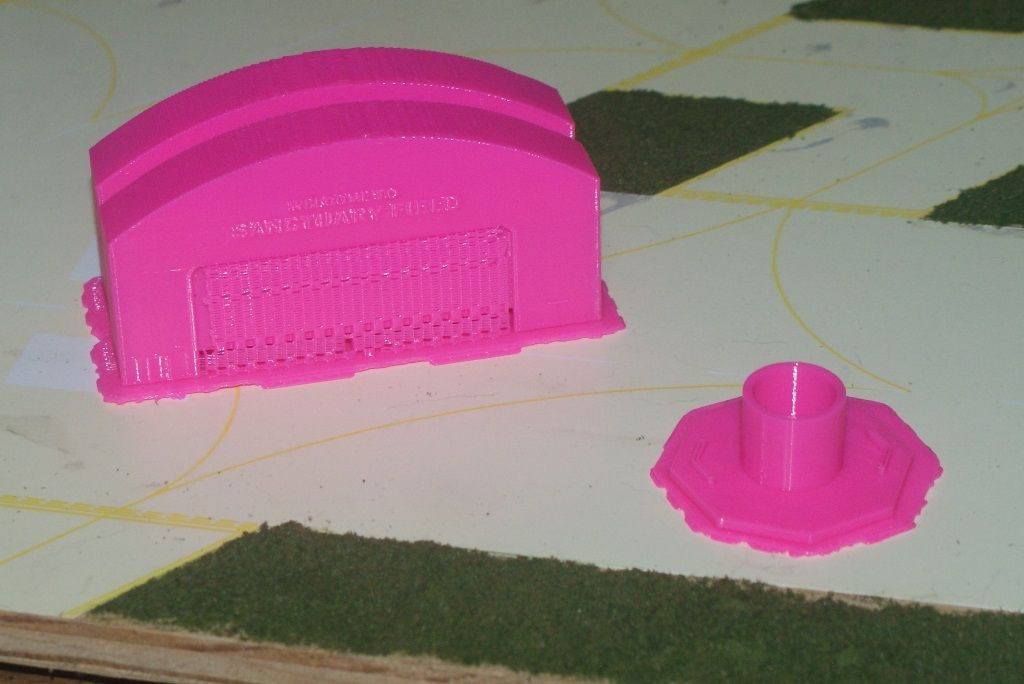
After priming them, the tower looks pretty good I think, but the hangars are messed up.  Due to the demand, you have to schedule an appointment to print your parts, so I made another appointment and had them print the other two hangars and a modified top for the tower.  The picture below shows how they appeared after printing.  You can see that there is support material that needs to be removed.


After removing this support material, which was somewhat difficult to do, the new hangars looked pretty good…


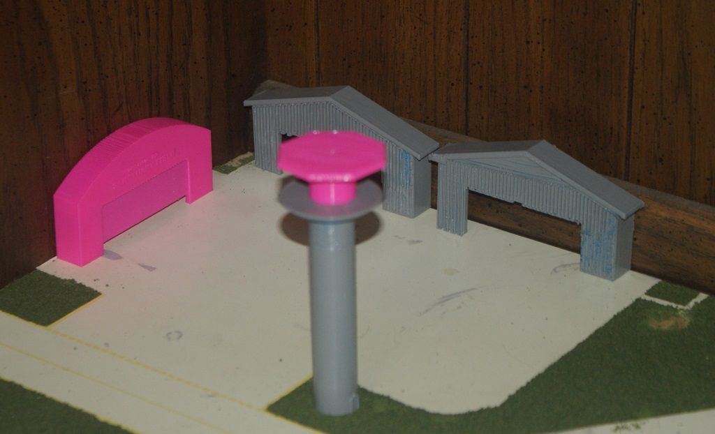
…And they look even better after priming.


Because I got good results on the second set of hangars, I scheduled another appointment to redo the initial hangars.  The picture below shows them as they printed.  You can see that they look a lot better than the initial ones and that the support material still hasn’t been removed.  The difference in print quality was the way they aligned the part for printing. 


I have more to report, but that’s enough for now.  Stay tuned for future updates.

JOIN OUR COMMUNITY!

Our community is FREE to join. To participate you must either login or register for an account.

SEARCH FORUMS
FREE NEWSLETTER
By signing up you may also receive reader surveys and occasional special offers. We do not sell, rent or trade our email lists. View our Privacy Policy.