Thanks, Ken! I'm as anxious as you are  .
.
Russ
Inserted 9/12/19
Adding the Drag Chute Tray
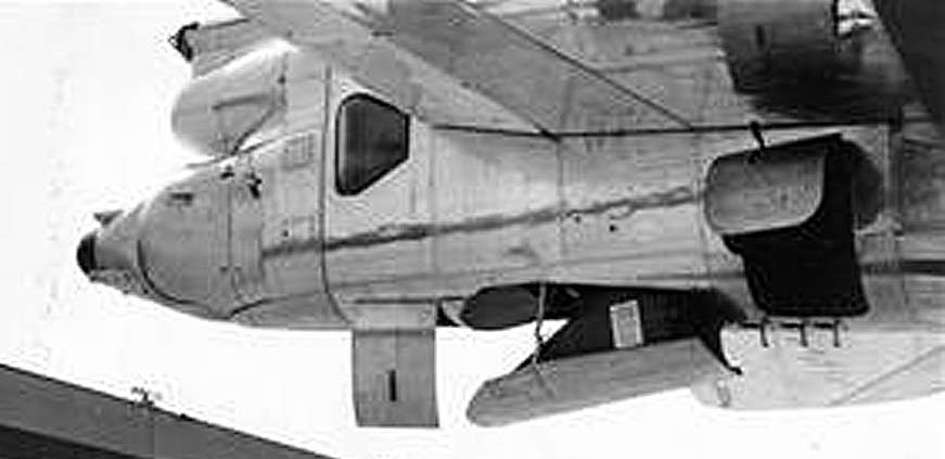
The B-52's massive wings were so far forward and had so much lift that the plane could not reduce landing speed by flaring like most aircraft. A drag chute was needed to slow it down enough so the brakes could be used without burning them up. The drag chute on the D-model was stored in a compartment in the bottom of the tail section, just forward of the gun turret, as show below. The drag chute tray was almost always extended while the aircraft was being turned around for it's next mission.

Determine how you are going to install the tray in the fuselage as this will determine the total height of the side and end panels. The simplest way is to glue one or more strips cross-wise up inside the fuselage and attach the tray to them.
1) The drag chute tray door is already outlined on the model. Correct any distortions in the outline and cut out the door.
2) The cut out door is 2 mm thick, which is too thick for the tray door so you will need to use it as a template and make a new door out of 0.5 mm thick sheet stock.
3) Once the new door is cut out, bend it slightly to conform to the curvature of the bottom of the fuselage.
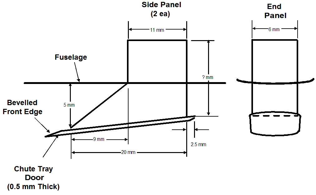
4) Determine the length of the side and end panels so that the sharp angle in the front of the side panels will be about even with the door opening when the tray is installed, then cut out the side and end panels according to the dimensions below.

5) Glue the end panel to the inside edges of the side panels.
6) Glue the assembled panels to the inside of the tray door according to the dimensions shown above.
7) Paint the side and end panels and the inside of the tray door green zinc chromate or olive drab.
8) Glue the assembled tray up inside the fuselage.
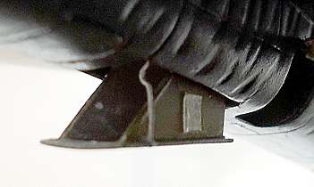
9) Construct the actuator arm from 0.5 mm/.020" plastic rod (Plastruct #90720) or equivalent as shown in the photo below. NOTE: The total length of the actuator arm will depend on the height of your side and end panels. The arm had a half-moon shaped kink in it near the door opening. Glue the long end of the arm to the door outside the side panel and the other end to the edge of the door opening.
10) There was also a placard on the right side panel which probably contained safety instructions. You can replicate it as I did with a thin piece of paper cut 3 mm x 4 mm.
11) Construct the actuator arm from 0.5 mm/.020" plastic rod (Plastruct #90720) or equivalent as shown in the photo below. NOTE: The total length of the actuator arm will depend on the height of your side and end panels. The arm had a half-moon shaped kink in it near the door opening. Glue the long end of the arm to the door outside the side panel and the other to the edge of the door opening.
12) There was also a placard on the right side panel which probably contained safety instructions. You can replicate it as I did with a thin piece of paper cut 3 mm x 4 mm.
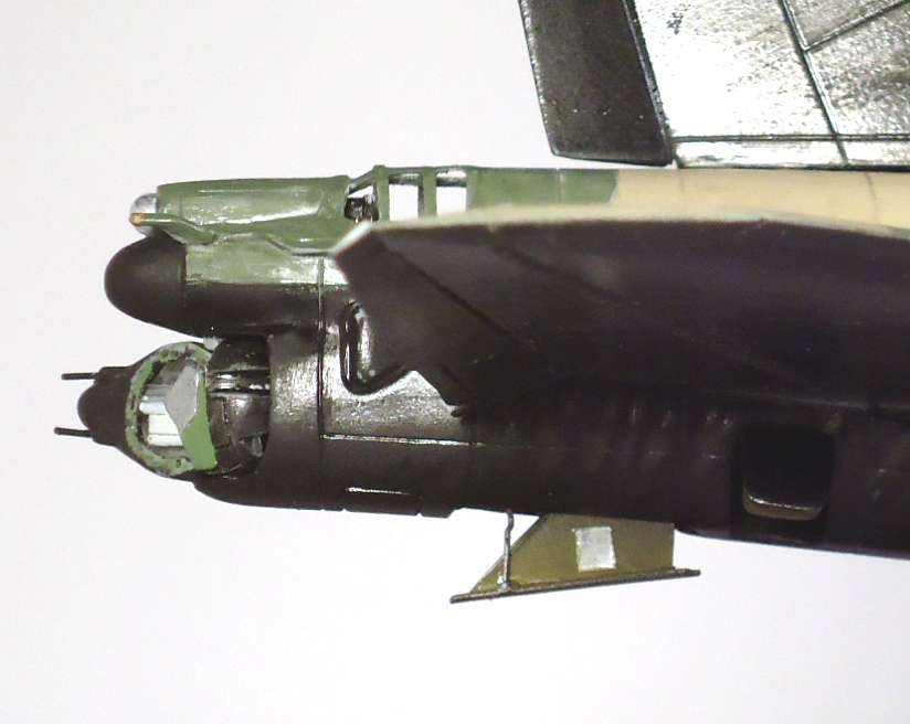
12) Paint the outside of the chute compartment door to match the underside of the aircraft. The finished chute tray is shown below.

